

Abstract
Modern biology is based largely on a reductionistic “dissection” approach—most cell biologists try to determine how complex biological systems work by removing their individual parts and studying the effects of this removal on the system. A variety of enzymatic and mechanical methods have been developed to dissect large cell assemblies like tissues and organs. Further, individual proteins can be inactivated or removed within a cell by genetic manipulations (e.g., RNAi or gene knockouts). However, there is a growing demand for tools that allow intracellular manipulations at the level of individual organelles. Laser microsurgery is ideally suited for this purpose and the popularity of this approach is on the rise among cell biologists. In this chapter, we review some of the applications for laser microsurgery at the subcellular level and describe practical requirements for laser microsurgery instrumentation demanded in the field. We also outline a relatively inexpensive but versatile laser microsurgery workstation that is being used in our laboratory. Our major thesis is that the limitations of the technology are no longer at the level of the laser, microscope, or software, but instead only in defining creative questions and in visualizing the target to be destroyed.
At last in an incredible manner he [Archimedes] burned up the whole Roman fleet. For by tilting a kind of mirror toward the sun he concentrated the sun's beam upon it; and owing to the thickness and smoothness of the mirror he ignited the air from this beam and kindled a great flame, the whole of which he directed upon the ships that lay at anchor in the path of the fire, until he consumed them all.1
I. History of the Field
A. The Genesis of “Micro-Photo-Surgery”
The origins of Cell Biology as a branch of “natural philosophy” can be traced to the English polymath Robert Hooke who, using a hand-crafted, leather and goldtooled compound light microscope (LM), published a book containing elaborate drawings of magnified objects which he called Micrographia. In this book, which became an immediate best-seller (and has been reprinted countless times), Hooke used the term “cell” to describe the repeating units seen in magnified slices of cork that resembled the monk cells of a monastery. Ironically, these repeating units were not actual cells but rather just the cellulose walls that surround cells in plant tissues. It took another 175 years of optical development and exploration, before Schleiden and Schwann (1839) convincingly asserted that cells are the fundamental building blocks of all life. In 1855, the Prussian physician and politician Virchow postulated that cells arise only from preexisting cells by reproduction and cannot be formed de novo from amorphous “living matter” or “protoplasma.” This principle, which Virchow eloquently formulated in Latin: “Omnis cellula e cellula (every cell [stems] from a cell) became a key principle of modern biology. Virchow also viewed the body as a “cell state in which each cell is a citizen,” and he considered disease to be simply “a conflict between the citizens of the state, caused by outer forces” (http://www.whonamedit.com/doctor.cfm/912.html). This breakthrough concept, coupled with the widespread availability of the compound LM, resulted in a new science of “cytology” in the late nineteenth century that was initially dedicated to categorizing the various types of cells and their sometimesvisible contents. The subsequent rapid accumulation of morphological data generated by this endeavor spawned an immense appreciation as to the true complexity and diversity of cells, which was brilliantly summarized by E. B. Wilson in his fundamental opus The Cell in Development and Heredity (Wilson, 1925).
By the early twentieth century, methods were available for removing many types of cells from an organism and culturing them as individuals in dishes (http://caat.jhsph.edu/pubs/animal_alts/appendix_c.htm). Near this time, cytologists also began seeking ways to dissect cells, so that they could determine the relationships between, and functions of their constituents. Toward this end, it quickly became apparent that approaches based on mechanical dissection were seldom successful, since they usually killed the specimen by rupturing the surrounding membrane (or cell wall). The search was on for a noninvasive approach that would allow scientists to selectively remove or destroy individual intracellular components without killing the cell outright.
Although the opening description of Archimedes' use of focused sunlight in 212 BC to destroy the Roman navy may be fanciful, the notion that light can be used to destroy objects is not. Like the concave mirrors allegedly used by Archimedes, microscopes also can focus light of a powerful illuminator on a tiny spot whose size is limited only by diffraction. Thus, it was natural for those working with microscopes to ultimately apply Archimedes' principle to manipulate cells. The first to intentionally use a focused light beam to destroy chosen cellular components appears to be Sergey Tschachotin (1883-1973), who in 1912 developed a method which came to be called “micro-photo-surgery” (Tschachotin, 1912). In his initial approach (Fig. 1), Tschachotin routed an appropriate wavelength of UV light through a quartz prism into the condenser lens of an LM. He controlled the area illuminated within the specimen by placing an aperture of the appropriate diameter in the object-conjugated plane (Fig. 1B). The only highintensity light available to Tschachotin at the time was that of magnesium sparks (Fig. 1C), which were then commonly used in photography. Fortunately, magnesium sparks contain a heavy 280-nm (UV) line that proved to be very useful for micro-photo-surgery. However, Tschachotin had to first solve the nontrivial problem of how to determine the position of the invisible UV microbeam in the field of view. He did this by using drops of fluorescein on a standard glass slide to see the beam via its induced fluorescence in the visible spectrum, and marked the position of the focused beam on the microscope eyepiece. Once this calibration step was completed, Tschachotin substituted the fluorescein slide with slides of real cells and the cell of choice was moved into position under the beam. In later years, Tschachotin used mercury arc lamps as the light source and uranium glass to visualize the UV. Remarkably, we still use many of the tricks Tschachotin developed almost a century ago for routine alignment of the laser microsurgery workstation housed in our laboratory.
Fig. 1.

One of the early micro-photo-surgery systems of Sergey Tschachotin. (A) Overview of the instrument. (B) General optical layout of the system: light generated by magnesium sparks is monochromatized by quartz prisms and selected wavelengths directed toward the microscope condenser. An aperture controls the size of the irradiated area. (C) Spark generator. Magnesium powder was ignited by the electrodes (Fb). The electric layout included a switch (Sch) for the step-up transformer (T) with a rheostat (W) and Amperemeter (labeled A), solenoid inductor (S) with two capacitors (labeled K) and, for safety reasons, an alternate spark site (Fs). Adapted from Tschachotin, 1938.
Tschachotin's list of achievements, which span over 60 years, is remarkable, and many of his experiments have become standard repeats for each new generation of microbeam researchers. Not only did he conduct the first study on the reaction of cells to different wavelengths of irradiation, but he also reported that micro-irradiation of sea urchin eggs induces parthenogenesis. He discovered photosensitization by noting that irradiating Paramecia with 310-nm light did not induce any detectable reaction unless they were first incubated in eosin. In a remarkable live-cell study, he proved that the pigment spot seen in Euglena gracilis is responsible for Euglena's reaction to light (i.e., it is the “eye” of the cell). Most of Tschachotin's work was done in Italy and France, although he also worked in Denmark, Germany, Croatia, and the United States. When Hitler's forces occupied France (1939), he was thrown into a concentration camp for writing Le Viol des Foules par la Propagande Politique (The Rape of the Crowds by Political Propaganda). He was released 8 months later after a direct petition from prominent German cytologists. In 1958, Tschachotin returned to Russia where he died in 1973. Because Tschachotin remained active in science until his departure, he was able to witness in his latter years the transformation of his micro-photo-surgery approach into laser microsurgery (Posudin, 1995).
B. The Middle Years: Laser-Based Microirradiation
As ingenious as Tschachotin was, the success of his work was limited by the fact that the brightfield optics used in microscopes during his time generated very limited contrast in live nonstained cells. As a result, the number of components (organelles) that could be clearly delineated within the cell was usually restricted to two: the nucleus and the cytoplasm. Tschachotin's experiments on the eye (pigment spot) of E. gracilis were, in a way, forced on him because the eye is the only naturally opaque organelle in this protist. Indeed, the fact that one cannot selectively destroy a target if it is not visible became the major obstacle to a more widespread use of micro-photo-surgery.
The “can't see, can't destroy” stalemate changed abruptly in the early 1950s with Frits Zernike's invention of phase-contrast LM, for which he won the Nobel Prize in 1953 (Zernike, 1955). Shortly thereafter other methods for generating contrast in living cells were also developed to a useful state, including polarization and differential interference contrast microscopy. These new optics allowed many organelles and subcellular structures to be visualized within the nucleus and cytoplasm of living cells including the nucleoli, mitochondria, stress fibers, and cilia/flagella of interphase cells, as well as the chromosomes and spindle fibers of dividing cells. When coupled in a creative manner to a UV microbeam and a cinematographic system, these new imaging modes allowed researchers to cut or destroy selected components, and then to follow the subsequent behavior of the cell. Zirkle and colleagues (Uretz et al., 1954; Zirkle and Bloom, 1953), for example, combined a UV microbeam with a phase-contrast microscope to prove (the already well-known fact) that destroying the kinetochore region of a chromosome inhibits motion of the chromosome. In a more biologically successful project, Forer (1965) combined a UV microbeam and polarization light microscopy to show that once severed, spindle (kinetochore) fibers in the cranefly spermatocyte regrew from the chromosome to the spindle pole. These original experiments have since been repeated on more than one occasion, although on different cell types, with increasingly sophisticated UV and then visible laser microbeams (LaFountain, Jr., et al., 2001; Maiato et al., 2004; Spurck et al., 1990).
The ability to visualize and thus target for destruction of many intracellular organelles resurrected biologist's interest in micro-photo-surgery. However, it immediately became apparent that there was a major problem of using lampgenerated UV light for this approach: since chromatin (DNA) effciently absorbs 280-nm light, all cellular systems are extremely sensitive to UV, which leads to unavoidable nonspecific (and not always easy to define) side effects (reviewed in Khodjakov et al., 1997b). This problem has been largely overcome with modern UV laser-based microirradiation system that allows the beam to be tightly focused (Colombelli et al., 2005). However, in microirradiation systems based on conventional light sources the irradiated area was defined by the size of the aperture used in the conjugated plane, and this often exceeded that required for the specific task. Thus, in the middle years “cell surgeons” could see their targets with relative clarity, but they still had to operate with “dull” scalpels. This dullness prompted investigators to experiment with alternative irradiation sources, often choosing those that simply already existed in a laboratory. These included, for example, the proton and α-particle beams of Zirkle and Bloom (1953) and Winson (1965), respectively. The latter study is a perfect example of what biologists are willing to cope with on the quest to understand how cells work. Because α-particles cannot be focused by light-microscope optics, Winson and Kuzin (1965) positioned slices of mica with small (several micrometer in diameter) holes in front of living cells so that certain parts of a cell were protected from the beam while others were exposed. This elaborate approach revealed that the deleterious effects of α-particles were due to their interaction with the nucleus (i.e., DNA damage). However, although potentially useful, proton and α-particle irradiation systems were so cumbersome that they had little chance of becoming a standard technique in cell biology.
A significant breakthrough in micro-photo-surgery came with the invention of lasers in 1959, and their commercialization in the 1960s, which provided a ready source of powerful and highly focusable light beams. The first laser “microirradiation” study on living cells can be traced to 1962 when Bessis et al. (1962), working in Paris (France), conducted a series of investigations on the effects of irradiating cell structures with a low-power Ruby Red laser. The conclusions of this work were that, in essence, nonnaturally pigmented cells did not respond to irradiation unless they were first sensitized by adding an exogenous chromophore (e.g., acridine orange, acridine red, alcian blue, psoralens, coumarins, Janus B green). This conclusion was then confirmed at the EM level, which also revealed that under the appropriate vital staining and laser power conditions, restricted and selective damage was created at the irradiated site (Storb et al., 1966).
In 1969, Michael Berns and his colleagues at the University of California (Irvine) showed, using an argon laser coupled to a phase-contrast microscope, that very small lesions could be easily placed at predetermined sites on selected chromosomes (Berns et al., 1969). Encouraged by their initial successes, this team began a series of studies, based on UV and later visible spectrum laser beams, on how cells react to the selective removal of various structures from the nucleolar organizer/primary constriction (Berns and Cheng, 1971; Berns et al., 1970b, 1972; Ohnuki et al., 1972) to the centrosome region (Berns and Richardson, 1977; Berns et al., 1977; Peterson and Berns, 1978). These studies were conducted on cells sensitized with chemical fluorophores such as acridine orange. However, Strahs and Berns (1979) discovered that stress fibers, mitochondria, and other organelles could be selectively cut or destroyed by 100- to 150-ns pulses of 532- or 537-nm (green) laser light, obtained from a Q-switched neodymium-doped yttrium aluminum garnet (Nd:YAG) laser, without any prior sensitization treatment. Under these circumstances the lesions created were identical to those produced by UV irradiation. The salient conclusion of this landmark study was that the interaction of light with biological systems is nonspecific and not restricted to a particular class of molecules. Thus, short pulses of highly focusable visible-spectrum laser light can be used to ablate a wide range of cell components.
The exact mechanism by which short pulses of visible laser light destroy biological components in the absence of photosensitization remains controversial (see other chapters in this book and a brief discussion later in this chapter). Regardless of the mechanism, lasers can be used to selectively destroy any structure clearly visible by light microscopy in a living cell with minimum collateral damage and without need for prior sensitization. Once this became clear, researchers began to use laser microsurgery to ablate most of the more conspicuous organelles within tissue culture cells, often just to prove that they could. A prime example here is the mitochondrion: when viewed by phase-contrast or differential contrast microscopy (DIC) LM, these thin wormlike structures suddenly disappear (i.e., the contrast between the structure and the surroundings is lost) when irradiated with laser pulses of sufficient energy (e.g., a single 7-ns 532-nm pulse from the workstation used in our laboratory). This occurs due to localized rupture of the mitochondrial membranes so that constituents of the mitochondrion are expelled into the cytoplasm (Fig. 2; also see Khodjakov et al., 2004b). Since first reported by Berns et al. (1970a), this result has been subsequently confirmed by many others (Adkisson et al., 1973; Moreno et al., 1973; Rattner et al., 1976; Salet, 1972). In fact, it appears that punching holes in mitochondria with new and improved lasers, without providing any additional insight into how these organelles work, has become a litmus test for proving the utility of a new system. Just last year there were at least three independent reports of this exact experiment (Colombelli et al., 2005; Shen et al., 2005; Shimada et al., 2005).
Fig. 2.
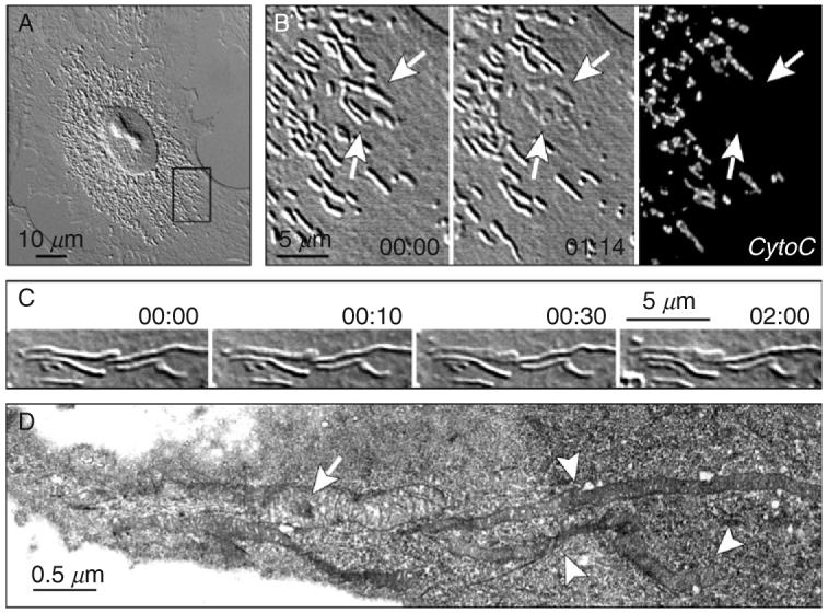
Rupturing the membrane of a single mitochondrion by laser microsurgery. (A) An interphase CV-1 cell (green monkey kidney) in culture. (B) Enlarged view of the area boxed in (A). Individual mitochondria appear as wormlike structures several micrometers long and diffraction limited in width. Irradiation of mitochondria with 7-ns pulses of 532-nm laser light results in the disappearance of the refractive-index gradient between the irradiated mitochondrion and surrounding cytoplasm [arrows indicate a group of five mitochondria individually irradiated (1 pulse/mitochondrion) between 00:00 and 01:14]. Immunostaining reveals that microirradiation results in the disappearance of intramitochondrial proteins, like cytochrome C, from the irradiated mitochondria. (C) A single mitochondrion was irradiated in a PtK1 cell (rat kangaroo kidney) (arrow in 00:00). (D) Same-cell serial-section electron microscopy analysis reveals that the irradiated mitochondrion is swollen (arrow) and its matrix is much less dense than in the surrounding, nonirradiated mitochondria (arrowheads). This is consistent with the loss of intramitochondrial proteins from the irradiated mitochondria. Time in minutes:seconds. See Khodjakov et al. (2004b) for more details.
Initially, the complexity of laser microirradiation systems restricted their distribution to just a few institutions specializing primarily in laser physics. However, in early 1980s Michael Berns started the laser microbeam program (LAMP) at the University of California (Irvine) which was (and remains) sponsored by the NIH Center for Research Resources as a National Biotechnology Resource. This facility provided Cell Biologists throughout the country with an opportunity to explore the applicability of laser microsurgery to their particular research programs. Giving biologists with little background in Physics unrestricted access to costly and sophisticated laser microsurgery workstations rapidly led to important new biological findings. In a very influential paper, for example, McNeill and Berns (1981) showed, by selectively destroying just one of the two sister kinetochores on a prometaphase chromosome, that the velocity with which a kinetochore moves is independent of the mass associated with it. This study also implied that the mechanism that moves chromosomes during spindle assembly is the same that moves them poleward during anaphase. In another notable study conducted at the LAMP facility, Rieder et al. (1986) reported that severed chromosome arms are ejected from the forming mitotic spindle in animal cells, meaning that they are under a constant away-from-the-pole pushing force (i.e., so called polar winds or polar ejection force; Fig. 3). Since their discovery, the polar ejection forces have become an important part of modeling how chromosome position is governed during mitosis (reviewed in Kapoor and Compton, 2002). Subsequent laser microsurgery studies proved that the forces acting on chromosome arms differ dramatically between animal cells, where spindle assembly is driven by the centrosome, and plant cells that lack this organelle (Fig. 4; also see Khodjakov et al., 1996).
Fig. 3.

Severing chromosome arms during mitosis in an animal (newt lung) cell. Selected frames from a time-lapse recording of an early prometaphase cell containing a monopolar spindle. 7-ns, 532-nm, 10-Hz laser pulses were used to separate the arms of one chromosome (arrows in A-C) from the centromere. The operation took ∼5 s (∼50 laser pulses). Once severed, the chromosome arms were ejected away from the spindle pole (arrowheads in D-F), while the central fragment containing the kinetochore moved closer to the spindle pole (arrows in D-F). Experiments like this proved the existence of a “spindle ejection force” or “polar winds” that act on chromosome arms (Rieder et al., 1986). Time in minutes:seconds.
Fig. 4.

Generating chromosome fragments with and without kinetochores during mitosis in a plant (endosperm of lily) cell. In this example, the laser microbeam was first used to sever the chromosome arms on the right (arrows in A and B) and left (arrowheads in B and C) sides of the centromere region, and then to slice the centromere in between the sister kinetochores (arrow in D). The entire operation (three cuts) took about 1 min and required ∼200 laser pulses (7-ns, 532-nm). In sharp contrast to animal cells (Fig. 3), in plants chromosome fragments containing kinetochores (arrows in D-F) as well as the chromosome arms (arrowheads in D-F) move toward the spindle pole with similar velocities. This reflects a dramatic difference in the distribution of forces during mitosis in plants and animals (Khodjakov et al., 1996). Time in minutes:seconds.
In the early 1990s, a DIC-based Nd:YAG laser microsurgery workstation was constructed in the Rieder laboratory at the Wadsworth Center (Albany, NY). This system (Cole et al., 1995) was patterned after the phase-contrast systems developed by Berns and colleagues, and it quickly proved that ready access to laser microsurgery could be an enormous benefit to a group of cell biologists. The Rieder laboratory had a long-standing interest in studying mitosis, cell cycle regulation, and the microtubule cytoskeleton. The extensive biological experience of this group allowed its members to formulate a number of questions that could only be answered by laser microsurgery. During the next several years this workstation was used to demonstrate, for example, that the spindle assembly checkpoint monitors kinetochore attachment (Rieder et al., 1995), that chromosomes containing a single kinetochore can congress to the equator of the forming spindle (Khodjakov et al., 1997a), and that entry into mitosis in vertebrate cells is guarded by a DNA damage checkpoint that reverses the cell cycle when triggered during early prophase (Rieder and Cole, 1998). Further, this same instrument was also used by other biologists to address a number of questions in systems as diverse as fungi to cranefly (Inoue et al., 1998; LaFountain, Jr., et al., 2001, 2002; Orokos et al., 2000).
As emphasized early on by Berns et al. (1981), Gaussian laser beams can actually generate a central “hot spot” inside the Airy disk. Thus, it is possible to select a beam energy at which damage to the specimen is restricted only to the “hot spot” at the peak intensity in the center of the Airy disk. This allows the resolution of laser microsurgery to surpass the Raleigh criterion which restricts the resolution of light microscopy. In practical turns, this means that lasers have been developed to the point where the “sharpness of the scalpel” ceases to be a limiting factor. With a properly conditioned laser beam and minimal practice, it is relatively easy to destroy every target that can be clearly delineated within a cell. Thus, by the late 1990s, the major remaining impediment in laser microsurgery became the fact that, even with modern contrast-enhanced DIC or phase-contrast microscopes, researchers are limited in their ability to see organelles in live cells. For this reason, most of the biologically meaningful experiments conducted during the “middle years” of micro-photo-surgery were aimed at solving problems related to large and/or high-contrast structures like chromosomes, nuclei, nucleoli, and mitochondria. Although, there were multiple attempts throughout the 1980s and 1990s to operate on other less conspicuous organelles like the centrosome (Berns and Richardson, 1977; Hyman, 1989; Koonce et al., 1984), the interpretation of these studies was always clouded by the fact that centrosomes are not visible, and thus their boundaries cannot be defined, in living vertebrate somatic cells. This, in turn, meant that the success or failure of the experiment could only be evaluated after the fact by fixing the cell for a subsequent serial-section electron microscopy analyses. Not surprisingly, the intense labor behind this same cell correlative LM/EM approach (Rieder and Cassels, 1999) severely limited the range of useful questions that could be cleanly answered by laser microsurgery.
In summary, by the end of the twentieth century it was evident that to extend the utility of laser microsurgery to the cell biologists a more direct method was needed to visualize components in living cells that were otherwise not visible because of their small size and/or physical properties, as well as to instantaneously assay the success or failure of an operation.
C. The Modern Era: A Synergy of Laser Microsurgery and GFP Imaging
In 1992, Doug Prasher and colleagues, working at the Woods Hole Oceanographic Institute (Massachusetts) successfully cloned green fluorescent protein (GFP), the small (238 amino acid) molecule responsible for the bioluminescence of the jellyfish Aequorea victoria (Prasher et al., 1992). Shortly thereafter Martin Chalfie, Doug Prasher, and others reported that GFP can be used for monitoring gene expression in prokaryotic (Escherichia coli) and eukaryotic (Caenorhabditis elegans) cells (Chalfie et al., 1994). They also predicted that it could be fused with other proteins to report their presence and location. The next year this prediction became a reality when several groups demonstrated that GFP-chimeras could be successfully used to illuminate mitochondria (Rizzuto et al., 1995). This started the “GFP revolution” in Cell Biology. The extent and speed with which this revolution changed how biologists study cells is readily apparent from a simple search of databases like PubMed. As of August of 2006, queries for GFP yielded ∼20,000 experimental papers and about 600 reviews!
Since 1995, a large number of fluorescent proteins have been constructed and their utility for studying cells demonstrated (see Giepmans et al., 2006 for review). This fluorescence-tagging technology can be used to visualize practically any macromolecular assembly in living cells ranging from yeast to vertebrates (Fig. 5). For our purposes it makes otherwise invisible small organelles suitable targets for laser microsurgery.
Fig. 5.

Examples of normally invisible intracellular structures that can be readily seen after GFP-labeling. (A-A′) A PtK1 (rat kangaroo kidney) cell in mitosis as visualized by DIC (A) or fluorescence (A′) microscopy. Although the approximate position of the two centrosomes in mitotic cells can be inferred from the DIC image (arrows), expression of a γ-tubulin/GFP fusion precisely delineates their boundaries (A′). (B-B′) A U2OS (human osteosarcoma) cell in metaphase of mitosis, as viewed by phase-contrast (B) and fluorescence (B′) microscopy. Normally kinetochores are not visible by phase-contrast or DICLM(B). However, after labeling with a CENP-B/GFP fusion protein they appear as paired bright dots associated with the chromosomes (B′). (C-C′) Neither microtubules nor nuclei are reproducibly seen in yeast (S. pombe) cells by DIC (C). However, simultaneously expressing Tub1(α-tubulin)/GFP and Uch2p (ubiquitin C-terminal hydrolase)/GFP fusion proteins in these cells clearly reveals these structures (C′). Arrows indicate the position of intranuclear mitotic spindle which is undetectable in DIC but clearly delineated in fluorescence. (A, B, B′, and C) = individual focal planes. (A′ and C′) = maximal-intensity projections through the entire cell volume collected at 0.2-μm Z-steps.
In 1997, the first proof-of-concept paper describing the laser ablation of GFP-labeled organelles was published (Khodjakov et al., 1997b). From this study it was clear that combining GFP-labeling with laser microsurgery produces a synergistic approach that allows one to achieve the precision of laser ablation that was never dreamt possible. Clear examples of this capability are illustrated by a series of studies that we conducted on the centrosomes in mammalian cells.
The centrosome is a minute organelle (Fig. 6) that, although absent in higher plants, is present as a single copy in all animal somatic cells (Ou and Rattner, 2004). When present, it acts as the principal microtubule-organizing center, but this function is not essential since a normal microtubule array can be assembled via centrosome-independent mechanisms. Yet, since mutations in core centrosomal components are lethal to the organism, this organelle clearly plays one or more essential vital functions (Basto et al., 2006; Bettencourt-Dias et al., 2005) which many generations of cell biologists have sought to identify. Another mystery of the centrosome is that it is built around two “centrioles”—complex macromolecular assemblies that replicate in a typical semiconservative fashion. As a result of this replication pattern, each centrosome contains one older (mother) centriole that was formed at least two cell cycles previously and one younger (daughter) centriole that was formed in the last cell cycle. The list of mysteries associated with the centrosome is extensive (it has been called The Central Enigma of Cell Biology—Wheatley, 1982) and, as outlined above (also see Uzbekov et al., 1995), there have been numerous unsuccessful attempts to remove it from living cells via UV and later laser irradiations. The limited success of past attempts can be ascribed partly to the subresolutional size of the centrosome, but also to the fact that it lacks a sharp natural boundary (like a surrounding membrane) to separate it from its surroundings (Fig. 6). However, it is now quite easy to delineate the entire centrosome, or just its component centrioles, by simply expressing fusions between the appropriate centrosomal/centriolar proteins and GFP (Fig. 6). Once a centrosome is so labeled, it becomes simple to destroy, without the ambiguity of previous studies, with just several laser pulses (Khodjakov et al., 1997b).
Fig. 6.

Structural organization of the centrosome in vertebrate somatic cells. (A) During interphase the centrosome is not detectable in live cells by DIC (left) but can be visualized via expression of GFP fusion proteins, for example, γ-tubulin/GFP (right). PtK1 cell. (B) During G1 the centrosome consists of two cylindrical structures, termed centrioles (left) surrounded by a cloud of amorphous pericentriolar material (PCM). γ-Tubulin (along with other components responsible for microtubule nucleation) resides in the PCM (right). Left image is a 500-nm thick section of a PtK1 cell treated with 10-μM Nocodazole (to depolymerize microtubules) and permeabilized with Triton X-100 prior to fixation. Right image is a maximal intensity projection of the same centrosome stained with an anti-γ-tubulin antibody. The raw dataset collected with 100× 1.4 NA PlanApo lens was deconvolved using super-resolution algorithms in the “AutoDeblur” software (AutoQuant, Watervliet, NY). (C) Centrioles visualized via expression of centrin-1/GFP fusion in CHO-K1 cells. G1 cells contain two individual centrioles. As cells enter S period the centrioles replicate and centrin dots become doubled (inset in S). During G2 daughter centrioles elongate which is manifested by increasing separation between the doubled centrin dots (insets in S and G2). (D) An individual centriole during G1 and replicating centrioles during mid-S in 100-nm thin EM section. Arrow indicates a short daughter centriole attached to the wall of the mother.
Using this GFP/laser microsurgery approach, we subsequently proved that animal cells form a functional bipolar spindle when both centrosomes are ablated before mitosis (Khodjakov et al., 2000). This finding overturned the 125-year-old dogma that centrosomes are required for spindle formation in animal somatic cells. Additional microsurgery studies further revealed that the assembly of new centrioles is not limited to the semiconservative replication pathway, disproving another common belief in centrosomal biology. Instead in vertebrate somatic cells, centrioles can also form via a de novo assembly pathway (Khodjakov et al., 2002; La Terra et al., 2005). Under some conditions, this pathway results in the simultaneous assembly of too many centrioles, suggesting that its activation contributes to the increase of centrosome numbers and to the chromosomal instability seen in many cancer cells (reviewed in Fukasawa, 2005; Nigg, 2002; Salisbury et al., 2004).
In addition to their biological significance, our centrosome ablation studies also revealed that laser microsurgery has now advanced to a precision that is remarkable: we can now reproducibly ablate just one of the two centrioles within a centrosome, with no detectable damage to the other centriole situated only 500 nm away (Fig. 7), using a laser workstation assembled in-house (see Section II). In practical terms, this means that at this time neither the “sharpness” of the microbeam scalpel nor the ability to see the targets are problematic for most live-cell microsurgery studies. Laser microsurgery has matured to the point where the current demands are to improve the automation and user-friendliness of the modern instruments.
Fig. 7.

Ablation of individual centrioles within diplosomes. (A) A HeLa (human epithelial) cell during S period (similar to the stage shown in Fig. 6C-S and D-S). The centrosome (arrow) is labeled via centrin/GFP expression. (B) A higher-magnification view of the centrosome reveals that both mother centrioles have already developed short daughters (arrows). Both daughter centrioles were irradiated (arrows in 00:00 and 00:01) with short series of laser pulses (∼10 per centriole), and 43 min later the cell was fixed for EM analysis. (C) Serial-section EM revealed that both daughter centrioles were completely ablated while mother centrioles remained structurally intact. Time in minutes:seconds.
II. Instrumentation for Subcellular Laser Microsurgery
A. Laser Microsurgery Workstations for Biologists: Practical Considerations
The ability to delineate otherwise invisible structures in the living cell allows microsurgery studies to be conducted that were previously impossible. As a result, laser microsurgery is becoming a much more popular tool in cell biology as evidenced by the fact that within last 2 years it has been used to generate exciting results in all of the major model systems, for example, Schizosaccharomyces pombe (Khodjakov et al., 2004a; Tolic-Norrelykke et al., 2004), C. elegans (Bringmann and Hyman, 2005; Yanik et al., 2004), Dictyostelium (Brito et al., 2005), Drosophila (Maiato et al., 2004, 2005), mammals (Botvinick et al., 2004; Colombelli et al., 2005; La Terra et al., 2005), and plants (Reinhardt et al., 2005). Once small, the club of “laser surgeons” is growing rapidly.
There are already relatively simple laser microsurgery systems available on the market (MicroPoint System—Photonics Science, Arlington Heights, IL). Further, it has been demonstrated that commercial multiphoton microscopes equipped with Ti:Sapphire lasers (e.g., Zeiss LSM510) can be used for laser microsurgery (Galbraith and Terasaki, 2003). However, most contemporary laser ablation studies are still conducted on systems assembled in-house that are based on different types of lasers and differ dramatically in their design. Often, this results in disagreements between groups regarding the type of instrumentation needed for a particular task. In this regard, there are numerous claims put in the literature that certain types of lasers (usually the most expensive ones) provide superior “precision” (size of ablated area) while other types should never be used for live-cell work. At one time, we were guilty of this pretentious selectivity by stating that UV lasers are inferior to our favorite 532-nm green light because they “unavoidably induce DNA damage” in live cells (Khodjakov et al., 1997b). However, this claim is no longer valid as shown by the Steltzer group who found that very sensitive PtK1 cells continue to progress through normal cell cycles after they were operated on with a picosecond UV laser beam (Colombelli et al., 2005). It has been claimed that femtosecond-range lasers provide much superior resolution when compared with the nanosecond- and picosecond-range lasers (Konig et al., 2001; Shen et al., 2005), and it has even been suggested that microsurgery with femtosecond lasers should be termed “nanosurgery” (Konig et al., 1999).
One goal of this chapter is to demystify the technique of laser microsurgery by emphasizing that it can be successfully conducted using a wide range of pulsed lasers. Although the physical mechanisms by which laser pulses destroy structures in live cells can differ between nanosecond and femtosecond lasers (Calmettes and Berns, 1983; Rau et al., 2006; Venugopalan et al., 2002; Vogel et al., 2005), the important point is that the biological consequences of organelle ablation appear to be the same (see discussion in Botvinick et al., 2004).
Under conditions of extremely short (femtoseconds) pulse durations, it is generally accepted that ablation occurs through multiphoton absorption (Schaffer et al., 2002; Vogel et al., 2005). On the other hand, for relatively long (nanosecond) pulses multiphoton absorption is highly improbable in such materials as water or glass. As a result, it is mostly assumed that in this case ablation is based on pressure wave propagation and/or cavitation bubble dynamics (Rau et al., 2006). Superfluously, this implies that the damage inflicted by nanosecond lasers is less localized than that generated by ultrashort pulses. However, in practice we find that the size of the damage inflicted by 532-nm nanosecond pulses in live cells can be as small as 250-300 nm. As mentioned above, our laser microsurgery workstation is capable of ablating individual centrioles inside a centrosome (Fig. 7). We can also cut cytoskeletal elements immediately adjacent to plasma membrane (Fig. 8) which would be impossible if the mechanism was based on the propagation of a pressure wave. Thus, the precision of nanosecond ablation in living cells equals that achieved with femtosecond lasers (Kumar et al., 2006; Shen et al., 2005).
Fig. 8.

Cutting cytoskeletal elements beneath the plasma membrane with nanosecond laser pulses. In this example actin filaments inside a filopodium were sliced with ∼5-10 pulses of 532-nm laser light. The typical diameter of a filopodium is just 0.2-0.4 μm, and thus the actin bundle is immediately adjacent to the plasma membrane. Nevertheless, the beam aimed at the center of this organelle (arrows) does not rupture the membrane revealing that damage inflicted by nanosecond lasers is highly localized.
Further, the total energy delivered to the cell during an operation is similar between femtosecond and nanosecond systems. Although most of our operations are done with ∼10-20 pulses (@20 Hz), multiple pulses are only needed to ensure that the often-moving target is solidly hit. In fact, a single ∼1-μJ pulse of 532-nm laser (8 ns) is suffcient to rupture an individual mitochondria (Fig. 2) or cut microtubules (Fig. 10). With femtosecond pulses rupturing a mitochondrion require several hundreds of 2-nJ pulses (Shen et al., 2005) which amasses to roughly the same total energy (∼1 μJ). Cutting microtubules with femtosecond pulses also required 1.5 μJ (1000 of 1.5-μJ pulses; Heisterkamp et al., 2006).
Fig. 10.

Examples of typical microsurgery (A-C) and photobleaching (D) experiments that can be used for evaluating the capabilities of a laser microsurgery workstation. (A) Severing an individual microtubule. A single 1.5-μJ (measured before the beam expander, Fig. 9) 8-ns pulse cuts an α-tubulin/GFP-labeled microtubule in a PtK2 cell (arrow). Notice that after the cut one of the exposed ends depolymerizes rapidly (the “plus” end), while the other remains stable (the “minus” end). (B) Severing a mitotic spindle in fission yeast (S. pombe) expressing Tub1/GFP. Similar to (A) except in this case a series of pulses (<10) was used to guarantee that the target is solidly hit. The halves of the spindle remain stable and eventually elongate (not shown, see Khodjakov et al., 2004a). (C-D) Comparison between laser ablation (C) and photobleaching (D) of an individual centriole in a human mammary epithelial (HMEC) cell. Irradiation with a series of 2.5-μJ 532-nm pulses (∼10) completely destroys the centriole (arrows in C). In sharp contrast, irradiation ∼200-ms irradiation with a 488-nm CW laser beam bleaches centrin/GFP molecules within the irradiated centrioles (arrows in D). Due to exchange of molecules between the irradiated centriole and the cytoplasmic pool GFP fluorescence gradually recovers. Time is in seconds in (A and B), and in minutes in (C and D).
The truth of the matter is that surgeons rarely think of how the scalpel cuts. Whether the object is annihilated by plasma or destroyed by a shock wave—the salient point is that it disappears. Thus far, there are no indications that in live cells the precision of near infrared femtosecond-laser ablations is any different from that achieved with green nanosecond or UV picosecond pulses. Where a direct comparison can be made, there appears to be little difference. A good example is illustrated by two recent microsurgery studies on the dynamics of spindle microtubules in fission yeast (Khodjakov et al., 2004a; Tolic-Norrelykke et al., 2004). Although, one study employed a femtosecond two-photon confocal system (Sacconi et al., 2005) and the other a 532-nm nanosecond laser (described in this chapter), the outcomes were quite similar. This being the case, for all practical purposes the reallife resolution and precision of the beams used in laser microsurgery are identical for nano- through femtosecond lasers.
For practitioners in the field, or for those who want to get involved, it often makes more sense to use the least expensive and most user-friendly system possible that will do the required job(s). In this regard, the high cost of purchasing and maintaining a femtosecond system currently prohibits its use as a “personal” instrument within an average-size biology laboratory. Obviously, there are specific applications where the use of femtosecond lasers is necessary. For example, near infrared femtosecond lasers have much better penetration depth and thus are indispensable for in-tissue ablations (Chung et al., 2006; Yanik et al., 2004). However, as outlined above, for laser microsurgery applications in relatively thin preparations, ranging from monolayers of cultured animal cells to yeast, relatively inexpensive green-light nanosecond-pulse lasers provide a more economical alternative. Importantly, small nanosecond-range lasers can be easily retrofitted to a research-grade inverted microscope, and such an upgrade can be performed with modest funds and a reasonable effort in the typical cell-biology laboratory environment.
B. General Layout of a Versatile Low-Cost Laser Microsurgery Workstation
Below we describe the layout of the system currently used in our laboratory (Fig. 9). Our design is based on the Nikon TE2000E2 microscope; however, in principle the same layout can be used to couple a laser to any research-grade inverted microscope. Although the total cost of our system is ∼$250K, most of the costs are for the microscope, spinning-disk confocal attachment, CCD cameras, and peripheral devices not related to the laser. The cost of the laser, optical elements, and mechanic components necessary to upgrade a high-end imaging workstation to a laser microsurgery system is currently ∼$30-35K.
Fig. 9.

Schematic layout of a basic laser microsurgery system. (1) Nd:YAG laser (Diva II, Thales Lasers, Paris, France) produces 532-nm, 8-ns pulses with about 5 mJ of light energy in each pulse. The laser is run at 20 Hz. (2) The beam is steered toward the microscope with front-surface dielectric mirrors. (3) Initial attenuation of the beam is achieved by the double reflection on a tilted uncoated glass parallel window. The level of attenuation can be adjusted (before the rest of the system is aligned) by varying the angle of incidence. (4) A 532-nm zero-order half-wave quartz waveplate in a rotatable mount to control beam polarization. (5) Glan-laser calcite polarizer permits only vertically polarized light to pass through. The combination of (4) and (5) allows us to precisely tune the energy of laser pulses reaching the microscope. (6) Focusable zoom beam expander (Special Optics, Wharton, NJ) mounted with two translational and two angular adjustment controls. (7) Beam combiner for simultaneous delivery of the ablation and 488-nm CW photobleaching beams. Conditioning of the photobleaching beam (8) is achieved in the way similar to that of the ablation beam. By adding additional beam combiners at this point additional laser beams can be delivered to the microscope (for example, 405-nm CW beam for photoactivation of PA-GFP). (9) Two-mirror periscope allows for elevating the beam to match the level of microscope's epiport and to rotate the polarization plane of the beam. (10) The beam enters the microscope through the lower epiport and is steered toward the objective lens with a custom-made dichroic mirror (525dcsp, Chroma, Brattleboro, VT). Not shown: mechanical shutter (Uniblitz, Vincent Associates, Rochester, NY) positioned between (3) and (4).
Our system is based on open-space in which both the laser and the microscope are situated on a vibration-isolation table, and the output of the laser is steered toward the microscope by a series of front-surface mirrors. In addition to being the least expensive option, all of the optical elements necessary for beam conditioning, as well as diagnostic equipment like a beam profiler and photo-detectors, can be easily placed at any point in the optical path. Further, an open-space layout allows one to easily deliver several laser beams to the same microscope. Indeed, our current system is also capable of diffraction-limited photobleaching with a continuous-wave 488-nm laser (Fig. 10). However, it is important to emphasize that open-beam laser systems require thoughtful considerations for laser safety. For starters, the system must be housed in a dedicated room that is accessible to only trained personnel. Fortunately, as a rule high-end imaging workstations are already housed in a dedicated space so that compliance with laser safety is not burdensome.
A variety of commercially available lasers are perfectly suited for laser microsurgery applications. We currently use a diode-pumped air-cooled Q-switched Nd:YAG laser (Diva II; Thales Lasers, Paris, France) which was chosen for its highly focusable (M2 < 1.2) true Gaussian-profile beam, pulse-to-pulse stability, small size (14.5 × 6 × 3.9 in.), and a very reasonable cost (currently under $25K). This laser operates in TEM00 mode outputting 8-ns 532-nm pulses at up to 20-Hz repetition rate.
One common misconception among cell biologists is that microsurgery can only be conducted with a very powerful laser. In fact, the single most important parameter that needs to be considered when choosing a laser is the quality of the beam. Unfortunately, most of the high beam-quality lasers available on the market produce at least three orders of magnitude more power than needed for diffraction-limited laser ablations in live cells. As a result, the laser beam needs to be significantly attenuated before it can be delivered to the specimen which, in principle, can be achieved in the laser head. However, in our laboratory we choose not to change any major laser operation settings because it could affect the pulse-to-pulse stability and pulse width. Instead we attenuate the beam in two stages between the laser and the microscope. For the first stage (∼500-fold) we use an uncoated 12-mm thick parallel-surfaces window (Newport Corporation, fused silica with λ/20 flatness) tilted ∼45° with respect to the laser beam. When passing through this window, a small portion of the beam reflects on both the front and then the rear surface of the window. Because of the large thickness of the window, the part of the original beam that passes straight through and the part that undergoes two internal reflections become spatially separated. This separation allows us to block the straight-through high-power beam with a beam-stop while directing the reflected beam toward the microscope (Fig. 9). By adjusting the tilt of the window, we can adjust the level of attenuation at this stage so that only 10 μJ/pulse is steered toward the microscope. This double-reflection approach also improves the polarization purity of the beam: the orthogonal polarization component (noise) that is inevitably present in the original beam is largely transmitted without internal reflection because the angle between the beam and the window is close to the Brewster angle.
The second attenuation step is achieved using an adjustable polarization rotator (half-wave plate) followed by a fixed Glan laser polarizer (Thorlabs). This approach allows us to attenuate the beam power approximately fivefold without significantly degrading the polarization purity of the beam. Further, the rotatable half-wave plate allows us to precisely tune the power of the beam, which is monitored immediately after the Glan polarizer with a laser power meter (818J-09B detector, Newport Corporation). Because all optical elements below this point remain constant, adjusting the power to a fixed value (currently ∼2.5 μJ on our system) allows us to compensate for any day-to-day fluctuations in the laser output (surprisingly common even in $25K lasers!). This is critical for ensuring that the energy delivered to the specimen remains constant. Although monitoring the energy of the beam before it passes through the objective lens does not reveal the absolute value of the energy delivered to the specimen, our method is convenient and quite reproducible. Here, it is noteworthy that achieving precise measurements of the light energy focused in the central spot of high-NA oil immersion lens are not a trivial task. We therefore empirically adjust the energy by monitoring the biological effects of laser irradiation (Fig. 10).
Because modern research-grade microscopes utilize infinity-corrected optics, creating a diffraction-limited spot in the focal plane of the objective lens is actually quite simple. All that needs to be done is to deliver a collimated beam to the back aperture of the objective. We achieve this by first expanding the attenuated beam with a focusable zoom beam-expander (Special Optics, 2-8× zoom, λ/8 beam distortion) mounted on a four-axis adjustable platform. The zoom expander allows us to precisely match the diameter of the beam to the size of the back aperture of the objective lens and to adjust beam collimation so that it focuses in the imaging plane. The expanded beam is steered toward the microscope with a series of front-surface mirrors mounted on standard adjustable mounts (Thorlabs) for precise beam alignment. The exact number of mirrors needed depends on the relative positions of the laser and the microscope on the optical table. The best way to minimize the footprint of the system is to mount the laser behind the microscope, facing away from the position of the microscope operator. Thus, the beam needs to be wrapped around the table (with several mirrors, Fig. 9), and also elevated to the height of the epiport on the microscope. The latter task is achieved by a two-mirror periscope to change the beam direction in the horizontal plane by 45°, which results in the rotation of the polarization plane by the same angle. This rotation is necessary for laser microsurgery on microscopes equipped for DIC. Most modern DIC microscopes utilize Wollaston prisms that are mounted just below the objective lens and oriented 45° with respect to the “left-right” axis of the microscope. Because the direction of polarization on all commercial lasers is either vertical (90°) or horizontal (0°), rotating the beam by 45° allows us to match the polarization of the beam to the sheer direction of the Wollaston prism so that the beam passes through the prism without major distortions.
The alignment of the laser beam in the layout described above is quite easy and can be achieved interactively by monitoring the position and shape of the beam in real-time via the same CCD camera used for imaging the specimen. For convenience, and to prevent potential damage to the CCD during alignment procedures, we use an additional neutral-density filter (OD3) that can be temporarily inserted into the beam at any point between the beam expander and the microscope. Alignment is then achieved by tilting the mirrors so that: (1) the focused beam becomes positioned in the center of the field of view of the objective lens and (2) its shape is symmetric indicating that the beam is centered and coaxial with the optical axis of the microscope. This type of alignment does not require an in-depth understanding of optics or laser physics, and graduate students or postdocs with minimal training in microscopy can easily perform it.
One of the salient features of our layout is that the focused laser beam remains stationary in the center of the field of view. Thus, for aiming the target needs to be moved into the beam. We achieve this by using a precise electronically controlled microscope stage (Ludl Electronic Products, Hawthorne, NY). This is less than an ideal approach because it makes ablation of large areas inside the cell virtually impossible. However, it is perfectly suited for ablating individual small objects such as centrosomes, kinetochores, or mitochondria. Further, the stage translation approach works fairly well for irradiating linear paths as needed when cutting across a chromosome or cytoskeletal assembly (e.g., actin filaments or microtubules within the spindle). In this type of operation, the operator opens the shutter and drives the stage (via joystick controls) along either the x- or y-axis. More sophisticated laser microsurgery systems usually employ special hardware and software that allow the beam to scan the field of view (see Botvinick and Berns, 2005; Colombelli et al., 2005, and Chapter 1 by Berns, this volume). This beam-scanning approach is obviously more versatile; however, it significantly increases the cost of the system and cannot be easily installed on an in-house assembled system.
One important consideration in designing a laser microsurgery workstation is that most laser ablations are now conducted in cells labeled with fluorescent proteins that are imaged either in wide-field epifluorescence or confocal mode. In epifluorescence, illumination of the object is achieved through the objective lens instead of a dedicated condenser and therefore, delivery of the laser beam to the back aperture of the lens must not interfere with the epifluorescence excitation. This presents an interesting problem because the 532-nm wavelength of the ablation laser is longer than both the 488-nm excitation and 510-nm emission peaks of the most common GFP isoform. Thus, the standard dichroic mirror used for imaging GFP fluorescence is transparent to the 532-nm wavelength and cannot be used to steer the laser beam towards the lens. Further, most multicolor dichroic mirrors do not perform well, particularly when the peak intensity of the laser pulses exceeds the intensity of the fluorescence excitation and emission light by several orders of magnitude. Until recently, the most common way to deal with this problem was to use two different dichroic mirrors mounted individually in two different filter cubes: one for observations and one for ablations. There are however two severe limitations associated with this approach. First, most filter-cube turrets on off-the-shelf microscopes are not suffciently reproducible to cycle filter cubes between the exact same positions. As a result, after a full cycle the orientation of mirrors with respect to the laser beam has changed slightly which in turn shifts the position of the laser beam in the imaging plane. This irreproducibility is particularly prominent in faster (and usually less-precise) turrets. More precise changers tend to be much slower, and this creates the second problem inherent in the switch-mirror approach. Because two dramatically different filter cubes are used for imaging and laser ablation, the target (specimen) cannot be observed during irradiation. This feature makes it much more diffcult to precisely aim the laser beam at the target as the latter often changes position during the 1-2 s required for switching the filter cubes. Further, the immediate response of the irradiated structure to the beam cannot be observed. Fortunately, some of the modern research-grade inverted microscopes can now be equipped with two independent filter-cube assemblies that provide for independent deliveries of the epifluorescence excitation and the ablation-laser beam. This feature, which we utilize in our system, makes it possible to steer the 532-nm beam of the cutting laser toward the lens by a stationary dichroic mirror positioned in the lower filter-cube turret, while the top (motorized) turret hosts the standard filter cube for imaging GFP-fluorescence (Fig. 9). This layout allows us to avoid problems associated with “wobbling” of the laser beam and at the same time to continuously observe the target during the operation. Finally, our system can operate both as a wide-field fluorescence and a spinning-disk confocal microscope. In the latter case, the top filter cube is rotated out of the optical path, and the excitation light of the confocal head illuminates the specimen through the laser dichroic (Fig. 9).
As noted above, an added bonus of using the open-space layout is that it supports the delivery of several laser beams to the same microscope simultaneously. This can be achieved by situating additional lasers (e.g., 488-nm CW laser for GFP photobleaching or 405-nm CW laser for photoactivation of PA-GFP) on the same table and by steering their beams toward the same epiport of the microscope in the manner described above. Combining the beams can be easily achieved by using either a conventional 50/50 beam-splitter cube or a round wedge-prism (Thorlabs part number PS814), which is less costly and provides a higher quality beam because of the smaller number of reflective surfaces. In this design, the ablation beam undergoes distortion on only two surfaces with little attenuation. The bleaching beam hits the surface of this window at sharp angle, so that the front-surface reflection follows the same path toward the microscope as the transmitted ablation beam (Fig. 9). The intensity of such a reflected beam (∼4%) is more than sufficient for photobleaching a diffraction-limited spot which requires about a hundred microwatts with a PlanApo 100× 1.4 NA objective. The ability to photobleach and ablate intracellular components in the same cell has provided valuable information on the dynamics of microtubules in yeast and animal cells (Khodjakovs et al., 2004a; Kumar et al., 2006; Magidson et al., 2006; Maiato et al., 2004, 2005).
The laser microsurgery/photobleaching system described in this chapter requires minimal maintenance costs (although we highly recommend purchasing a comprehensive service contract to cover potential malfunctions of the laser). However, it is surprisingly versatile as evident from the number of illustrations presented in this chapter.
Acknowledgments
We acknowledge use of Wadsworth Center's EM core facility. Our work is sponsored by grants from the NIH (GM59363 to A.K. and GM40198 to C.L.R.) and HFSP (RGP0064 to A.K.). Construction of the laser microsurgery workstation was supported in par by Summer Research Fellowship from Nikon/Marine Biological Laboratory (2003 to A.K.). We thank Dr. Zhenye Yang for the images used in Fig. 5B. Requests for technical details of our system should be addressed to Dr. Valentin Magidson (valentin@wadsworth.org). The authors declare that they have no competing financial interests.
Footnotes
Dio's Roman History, translated by Earnest Cary Loeb Classical Library, Harvard University Press, Cambridge, 1914, Vol. II, p. 171.
References
- Adkisson KP, Baic D, Burgott SL, Cheng WK, Berns MW. Argon laser micro-irradiation of mitochondria in rat myocardial cells in tissue culture. IV. Ultrastructural and cytochemical analysis of minimal lesions. J. Mol. Cell. Cardiol. 1973;5:559–564. doi: 10.1016/0022-2828(73)90008-4. [DOI] [PubMed] [Google Scholar]
- Basto R, Lau J, Vinogradova T, Gardiol A, Woods CG, Khodjakov A, Raff JW. Flies without centrioles. Cell. 2006;125:1375–1386. doi: 10.1016/j.cell.2006.05.025. [DOI] [PubMed] [Google Scholar]
- Berns MW, Aist J, Edwards J, Strahs K, Girton J, McNeill P, Rattner JB, Kitzes M, Hammer-Wilson M, Liaw LH, Siemens A, Koonce M, et al. Laser microsurgery in cell and developmental biology. Science. 1981;213:505–513. doi: 10.1126/science.7017933. [DOI] [PubMed] [Google Scholar]
- Berns MW, Cheng WK. Are chromosome secondary constrictions nucleolar organizers? A re-examination using a laser microbeam. Exp. Cell Res. 1971;69:185–192. doi: 10.1016/0014-4827(71)90324-7. [DOI] [PubMed] [Google Scholar]
- Berns MW, Floyd AD, Adkisson K, Cheng WK, Moore L, Hoover G, Ustick K, Burgott S, Osial T. Laser microirradiation of the nucleolar organizer in cells of the rat kangaroo (Potorous tridactylis). Reduction of nucleolar number and production of micronucleoli. Exp. Cell Res. 1972;75:424–432. doi: 10.1016/0014-4827(72)90449-1. [DOI] [PubMed] [Google Scholar]
- Berns MW, Gamaleja N, Olson R, Duffy C, Rounds DE. Argon laser micro-irradiation of mitochondria in rat myocardial cells in tissue culture. J. Cell. Physiol. 1970a;76:207–213. doi: 10.1002/jcp.1040760211. [DOI] [PubMed] [Google Scholar]
- Berns MW, Ohnuki Y, Rounds DE, Olson RS. Modification of nucleolar expression following laser micro-irradiation of chromosomes. Exp. Cell Res. 1970b;60:133–138. doi: 10.1016/0014-4827(70)90498-2. [DOI] [PubMed] [Google Scholar]
- Berns MW, Rattner JB, Brenner S, Meredith S. The role of the centriolar region in animal cell mitosis. A laser microbeam study. J. Cell Biol. 1977;72:351–367. doi: 10.1083/jcb.72.2.351. [DOI] [PMC free article] [PubMed] [Google Scholar]
- Berns MW, Richardson SM. Continuation of mitosis after selective laser microbeam destruction of the centriolar region. J. Cell Biol. 1977;75:977–982. doi: 10.1083/jcb.75.3.977. [DOI] [PMC free article] [PubMed] [Google Scholar]
- Berns MW, Rounds DE, Olson RS. Effects of laser micro-irradiation on chromosomes. Exp. Cell Res. 1969;56:292–298. doi: 10.1016/0014-4827(69)90016-0. [DOI] [PubMed] [Google Scholar]
- Bessis M, Gires F, Mayer G, Nomarski G. Irradiation des organites cellulaires a l'aide d'un Laser a rubis. Comptes Rendus de l Academie des Sciences. 1962;255:1010–1012. [Google Scholar]
- Bettencourt-Dias M, Rodrigues-Martins A, Carpenter L, Riparbelli M, Lehmann L, Gatt MK, Carmo N, Ballox F, Callaini G, Glover DM. SAK/PLK4 is required for centriole duplication and flagella development. Curr. Biol. 2005;15:2199–2207. doi: 10.1016/j.cub.2005.11.042. [DOI] [PubMed] [Google Scholar]
- Botvinick EL, Berns MW. Internet-based robotic laser scissors and tweezers microscopy. Microsc. Res. Tech. 2005;68:65–74. doi: 10.1002/jemt.20216. [DOI] [PubMed] [Google Scholar]
- Botvinick EL, Venugopalan V, Shah JV, Liaw LH, Berns MW. Controlled ablation of microtubules using a picosecond laser. Biophys. J. 2004;87:4203–4212. doi: 10.1529/biophysj.104.049528. [DOI] [PMC free article] [PubMed] [Google Scholar]
- Bringmann H, Hyman AA. A cytokinesis furrow is positioned by two consecutive signals. Nature. 2005;436:731–734. doi: 10.1038/nature03823. [DOI] [PubMed] [Google Scholar]
- Brito DA, Strauss J, Magidson V, Tikhonenko I, Khodjakov A, Koonce MP. Pushing forces drive the comet-like motility of microtubule arrays in Dictyostelium. Mol. Biol. Cell. 2005;16:3334–3340. doi: 10.1091/mbc.E05-01-0057. [DOI] [PMC free article] [PubMed] [Google Scholar]
- Calmettes PP, Berns MW. Laser-induced multiphoton processes in living cells. Proc. Natl. Acad. Sci. USA. 1983;80:7197–7199. doi: 10.1073/pnas.80.23.7197. [DOI] [PMC free article] [PubMed] [Google Scholar]
- Chalfie M, Tu Y, Euskirchen G, Ward WW, Prasher DC. Green fluorescent protein as a marker for gene expression. Science. 1994;263:802–805. doi: 10.1126/science.8303295. [DOI] [PubMed] [Google Scholar]
- Chung SH, Clark DA, Gabel CV, Mazur E, Samuel AD. The role of the AFD neuron in C. elegans thermotaxis analyzed using femtosecond laser ablation. BMS Neurosci. 2006;7:30. doi: 10.1186/1471-2202-7-30. [DOI] [PMC free article] [PubMed] [Google Scholar]
- Cole RW, Khodjakov A, Wright WH, Rieder CL. A differential interference contrast-based light microscopic system for laser microsurgery and optical trapping of selected chromosomes during mitosis in vivo. J. Microsc. Soc. Am. 1995;1:203–215. [Google Scholar]
- Colombelli J, Reynaud EG, Rietdorf J, Pepperkork R, Stelzer EH. In vivo selective cytoskeleton dynamics quantification in interphase cells induced by pulsed ultraviolet laser nanosurgery. Traffic. 2005;6:1093–1102. doi: 10.1111/j.1600-0854.2005.00334.x. [DOI] [PubMed] [Google Scholar]
- Forer A. Local reduction of spindle fiber birefringence in living Nephrotoma suturalis (Loew) spermatocytes induced by ultraviolet microbeam irradiation. J. Cell Biol. 1965;25:95–117. doi: 10.1083/jcb.25.1.95. [DOI] [PMC free article] [PubMed] [Google Scholar]
- Fukasawa K. Centrosome amplification, chromosome instability and cancer development. Cancer Lett. 2005;230:6–19. doi: 10.1016/j.canlet.2004.12.028. [DOI] [PubMed] [Google Scholar]
- Galbraith JA, Terasaki M. Controlled damage in thick specimens by multiphoton excitation. Mol. Biol. Cell. 2003;14:1808–1817. doi: 10.1091/mbc.E02-03-0163. [DOI] [PMC free article] [PubMed] [Google Scholar]
- Giepmans BN, Adams SR, Ellisman MH, Tsien RY. The fluorescent toolbox for assessing protein location and function. Science. 2006;312:217–224. doi: 10.1126/science.1124618. [DOI] [PubMed] [Google Scholar]
- Heisterkamp A, Maxwell IZ, Mazur E, Underwood JM, Nickerson JA, Kumar J, Ingber DE. Pulse energy dependence of subcellular dissection by femtosecond laser pulses. Optics Express. 2006;13:3690–3696. doi: 10.1364/opex.13.003690. [DOI] [PubMed] [Google Scholar]
- Hyman AA. Centrosome movement in the early divisions of Caenorhabditis elegans: A cortical site determining centrosome position. J. Cell Biol. 1989;109:1185–1193. doi: 10.1083/jcb.109.3.1185. [DOI] [PMC free article] [PubMed] [Google Scholar]
- Inoue S, Yoder OC, Turgeon BG, Aist JR. A cytoplasmic dynein required for mitotic aster formation in vivo. J. Cell Sci. 1998;111:2607–2614. doi: 10.1242/jcs.111.17.2607. [DOI] [PubMed] [Google Scholar]
- Kapoor TM, Compton DA. Searching for the middle ground: Mechanisms of chromosome alignment during mitosis. J. Cell Biol. 2002;157:551–556. doi: 10.1083/jcb.200202073. [DOI] [PMC free article] [PubMed] [Google Scholar]
- Khodjakov A, Cole RW, Bajer AS, Rieder CL. The force for poleward chromosome motion in Haemanthus cells acts along the length of the chromosome during metaphase but only at the kinetochore during anaphase. J. Cell Biol. 1996;132:1093–1104. doi: 10.1083/jcb.132.6.1093. [DOI] [PMC free article] [PubMed] [Google Scholar]
- Khodjakov A, Cole RW, McEwen BF, Buttle KF, Rieder CL. Chromosome fragments possessing only one kinetochore can congress to the spindle equator. J. Cell Biol. 1997a;136:229–240. doi: 10.1083/jcb.136.2.229. [DOI] [PMC free article] [PubMed] [Google Scholar]
- Khodjakov A, Cole RW, Oakley BR, Rieder CL. Centrosome-independent mitotic spindle formation in vertebrates. Curr. Biol. 2000;10:59–67. doi: 10.1016/s0960-9822(99)00276-6. [DOI] [PubMed] [Google Scholar]
- Khodjakov A, Cole RW, Rieder CL. A synergy of technologies: Combining laser microsurgery with green fluorescent protein tagging. Cell Motil. Cytoskeleton. 1997b;38:311–317. doi: 10.1002/(SICI)1097-0169(1997)38:4<311::AID-CM1>3.0.CO;2-6. [DOI] [PubMed] [Google Scholar]
- Khodjakov A, La Terra S, Chang F. Laser microsurgery in fission yeast: Role of the mitotic spindle midzone in anaphase B. Curr. Biol. 2004a;14:1330–1340. doi: 10.1016/j.cub.2004.07.028. [DOI] [PubMed] [Google Scholar]
- Khodjakov A, Rieder C, Mannella CA, Kinnally KW. Laser micro-irradiation of mitochondria: Is there an amplified mitochondrial death signal in neural cells? Mitochondrion. 2004b;3:217–227. doi: 10.1016/j.mito.2003.10.002. [DOI] [PubMed] [Google Scholar]
- Khodjakov A, Rieder CL, Sluder G, Cassels G, Sibon OC, Wang CL. De novo formation of centrosomes in vertebrate cells arrested during S phase. J. Cell Biol. 2002;158:1171–1181. doi: 10.1083/jcb.200205102. [DOI] [PMC free article] [PubMed] [Google Scholar]
- Konig K, Riemann I, Fischer P, Halbhuber KJ. Intracellular nanosurgery with near infrared femtosecond laser pulses. Cell. Mol. Biol. 1999;45:195–201. [PubMed] [Google Scholar]
- Konig K, Riemann I, Fritzsche W. Nanodissection of human chromosomes with near-infrared femtosecond laser pulses. Optics Lett. 2001;26:819–821. doi: 10.1364/ol.26.000819. [DOI] [PubMed] [Google Scholar]
- Koonce MP, Cloney RA, Berns MW. Laser irradiation of centrosomes in newt eosinophils: Evidence of centriole role in motility. J. Cell Biol. 1984;98:1999–2010. doi: 10.1083/jcb.98.6.1999. [DOI] [PMC free article] [PubMed] [Google Scholar]
- Kumar J, Maxwell IZ, Heisterkamp A, Polte TR, Lele TP, Salanga M, Mazur E, Ingber DE. Viscoelastic retraction of single living stress fibers and its impact on cell shape, cytoskeletal organization, and extracellular matrix mechanics. Biophys. J. 2006;90:3762–3773. doi: 10.1529/biophysj.105.071506. [DOI] [PMC free article] [PubMed] [Google Scholar]
- La Terra S, English CN, Hergert P, McEwen BF, Sluder G, Khodjakov A. The de novo centriole assembly pathway in HeLa cells: Cell cycle progression and centriole assembly/maturation. J. Cell Biol. 2005;168:713–720. doi: 10.1083/jcb.200411126. [DOI] [PMC free article] [PubMed] [Google Scholar]
- LaFountain JR, Jr., Cole RW, Rieder CL. Partner telomeres during anaphase in crane-fly spermatocytes are connected by an elastic tether that exerts a backward force and resists poleward motion. J. Cell Sci. 2002;115:1541–1549. doi: 10.1242/jcs.115.7.1541. [DOI] [PubMed] [Google Scholar]
- LaFountain JR, Jr., Oldenbourg R, Cole RW, Rieder CL. Microtubule flux mediates poleward motion of acentric chromosome fragments during meiosis in insect spermatocytes. Mol. Biol. Cell. 2001;12:4054–4065. doi: 10.1091/mbc.12.12.4054. [DOI] [PMC free article] [PubMed] [Google Scholar]
- Magidson V, Chang F, Khodjakov A. Regulation of cytokinesis by spindle-pole bodies. Nat. Cell Biol. 2006;8:891–893. doi: 10.1038/ncb1449. [DOI] [PubMed] [Google Scholar]
- Maiato H, Khodjakov A, Rieder CL. Drosophila CLASP is required for the incorporation of microtubule subunits into fluxing kinetochore fibres. Nat. Cell Biol. 2005;7:42–47. doi: 10.1038/ncb1207. [DOI] [PMC free article] [PubMed] [Google Scholar]
- Maiato H, Rieder CL, Khodjakov A. Kinetochore-driven formation of kinetochore fibers contributes to spindle assembly during animal mitosis. J. Cell Biol. 2004;167:831–840. doi: 10.1083/jcb.200407090. [DOI] [PMC free article] [PubMed] [Google Scholar]
- McNeill PA, Berns MW. Chromosome behavior after laser microirradiation of a single kinetochore in mitotic PtK2 cells. J. Cell Biol. 1981;88:543–553. doi: 10.1083/jcb.88.3.543. [DOI] [PMC free article] [PubMed] [Google Scholar]
- Moreno G, Salet C, Vinzens F. Etude en microscpie electronique des mitochondries de cellules en culture de tissus apres micro-irradiation par laser. Journal de Microscopie et de Biologie Cellulaire. 1973;16:269–278. [Google Scholar]
- Nigg EA. Centrosome aberrations: Cause or consequence of cancer progression? Nat. Rev. Cancer. 2002;2:815–825. doi: 10.1038/nrc924. [DOI] [PubMed] [Google Scholar]
- Ohnuki Y, Rounds DE, Olson RS, Berns MW. Laser microbeam irradiation of the juxtanucleolar region of prophase nucleolar chromosomes. Exp. Cell Res. 1972;71:132–144. doi: 10.1016/0014-4827(72)90271-6. [DOI] [PubMed] [Google Scholar]
- Orokos DD, Cole RW, Travis JL. Organelles are transported on sliding microtubules in Reticulomyxa. Cell Motil. Cytoskeleton. 2000;47:296–306. doi: 10.1002/1097-0169(200012)47:4<296::AID-CM4>3.0.CO;2-4. [DOI] [PubMed] [Google Scholar]
- Ou Y, Rattner JB. The centrosome in higher organisms: Structure, composition, and duplication. Int. Rev. Cytol. 2004;238:119–182. doi: 10.1016/S0074-7696(04)38003-4. [DOI] [PubMed] [Google Scholar]
- Peterson SP, Berns MW. Evidence for centriolar region RNA functioning in spindle formation in dividing PTK2 cells. J. Cell Sci. 1978;34:289–301. doi: 10.1242/jcs.34.1.289. [DOI] [PubMed] [Google Scholar]
- Posudin Yu., I . Biophysisist Sergei Tschachotin Natl. Univ. Publ Kiev; Agricult: 1995. pp. 1–92. [Google Scholar]
- Prasher DC, Eckenrode VK, Ward WW, Prendergast FG, Cormier MJ. Primary structure of the Aequorea victoria green-fluorescent protein. Gene. 1992;111:229–233. doi: 10.1016/0378-1119(92)90691-h. [DOI] [PubMed] [Google Scholar]
- Rattner JB, Lifsics M, Meredith S, Berns MW. Argon laser microirradiation of mitochondria in rat myocardial cells. VI. Correlation of contractility and ultrastructure. J. Mol. Cell. Cardiol. 1976;8:239–248. doi: 10.1016/0022-2828(76)90039-0. [DOI] [PubMed] [Google Scholar]
- Rau KR, Quinto-Su PA, Hellman AN, Venugopalan V. Pulsed laser microbeam-induced cell lysis: Time-resolved imaging and analysis of hydrodynamic effects. Biophys. J. 2006;91:317–329. doi: 10.1529/biophysj.105.079921. [DOI] [PMC free article] [PubMed] [Google Scholar]
- Reinhardt D, Frenz M, Mandel T, Kuhlemeier C. Microsurgical and laser ablation analysis of leaf positioning and dorsoventral patterning in tomato. Development. 2005;132:15–26. doi: 10.1242/dev.01544. [DOI] [PubMed] [Google Scholar]
- Rieder CL, Cassels G. Correlative light and electron microscopy of mitotic cells in monolayer cultures. Methods Cell Biol. 1999;61:297–315. doi: 10.1016/s0091-679x(08)61987-1. [DOI] [PubMed] [Google Scholar]
- Rieder CL, Cole RW. Entry into mitosis in vertebrate somatic cells is guarded by a chromosome damage checkpoint that reverses the cell cycle when triggered during early but not late prophase. J. Cell Biol. 1998;142:1013–1022. doi: 10.1083/jcb.142.4.1013. [DOI] [PMC free article] [PubMed] [Google Scholar]
- Rieder CL, Cole RW, Khodjakov A, Sluder G. The checkpoint delaying anaphase in response to chromosome monoorientation is mediated by an inhibitory signal produced by unattached kinetochores. J. Cell Biol. 1995;130:941–948. doi: 10.1083/jcb.130.4.941. [DOI] [PMC free article] [PubMed] [Google Scholar]
- Rieder CL, Davison EA, Jensen LC, Cassimeris L, Salmon ED. Oscillatory movements of monooriented chromosomes and their position relative to the spindle pole result from the ejection properties of the aster and half-spindle. J. Cell Biol. 1986;103:581–591. doi: 10.1083/jcb.103.2.581. [DOI] [PMC free article] [PubMed] [Google Scholar]
- Rizzuto R, Brini M, Pizzo P, Murgia M, Pozzan T. Chimeric green fluorescent protein as a tool for visualizing subcellular organelles in living cells. Curr. Biol. 1995;5:635–642. doi: 10.1016/s0960-9822(95)00128-x. [DOI] [PubMed] [Google Scholar]
- Sacconi L, Tolic-Norrelykke IM, Antolini R, Pavone FS. Combined intracellular three-dimensional imaging and selective nanosurgery by a nonlinear microscope. J. Biomed. Optics. 2005;10:14002. doi: 10.1117/1.1854675. [DOI] [PubMed] [Google Scholar]
- Salet C. A study of beating frequency of a single myocardial cell. 1. Q-switched laser micro-irradiation of mitochondria. Exp. Cell Res. 1972;73:360–366. doi: 10.1016/0014-4827(72)90059-6. [DOI] [PubMed] [Google Scholar]
- Salisbury JL, D'Assoro AB, Lingle WL. Centrosome amplification and the origin of chromosomal instability in breast cancer. J. Mammary Gland Biol. Neoplasia. 2004;9:275–283. doi: 10.1023/B:JOMG.0000048774.27697.30. [DOI] [PubMed] [Google Scholar]
- Schaffer CB, Nishimura N, Glezer EN, Kim AMT, Mazur E. Dynamics of femtosecond laser-induced breakdown in water from femtoseconds to microseconds. Optics Express. 2002;10:196–203. doi: 10.1364/oe.10.000196. [DOI] [PubMed] [Google Scholar]
- Shen N, Datta D, Schaffer P, LeDuc P, Ingber DE, Mazur E. Ablation of cytoskeletal filaments and mitochondria in live cells using a femtosecond laser nanoscissor. Mech. Chem. Biosys. 2005;2:17–25. [PubMed] [Google Scholar]
- Shimada T, Watanabe W, Matsunaga S, Higashi T, Ishii H, Fukui K, Isobe K, Itoh K. Intracellular disruption of mitochondria in a living HeLa cell with a 76-MHz femtosecond laser oscillator. Optics Express. 2005;13:9869–9880. doi: 10.1364/opex.13.009869. [DOI] [PubMed] [Google Scholar]
- Spurck TP, Stonington OG, Snyder JA, Pickett-Heaps JD, Bajer A, Mole-Bajer J. UV microbeam irradiations of the mitotic spindle. II. Spindle fiber dynamics and force production. J. Cell Biol. 1990;111:1505–1518. doi: 10.1083/jcb.111.4.1505. [DOI] [PMC free article] [PubMed] [Google Scholar]
- Storb R, Amy RT, Wertz B, Fauconnier B, Bessis M. An electron microscope study of vitally stained single cells irradiated with a ruby laser microbeam. J. Cell Biol. 1966;31:11–29. doi: 10.1083/jcb.31.1.11. [DOI] [PMC free article] [PubMed] [Google Scholar]
- Strahs KR, Berns MW. Laser microirradiation of stress fibers and intermediate filaments in non-muscle cells from cultured rat heart. Exp. Cell Res. 1979;119:31–45. doi: 10.1016/0014-4827(79)90332-x. [DOI] [PubMed] [Google Scholar]
- Tolic-Norrelykke IM, Sacconi L, Thon G, Pavone FS. Positioning and elongation of the fission yeast spindle by microtubule-based pushing. Curr. Biol. 2004;14:1181–1186. doi: 10.1016/j.cub.2004.06.029. [DOI] [PubMed] [Google Scholar]
- Tschachotin S. Die Mikroskopische Strahlenstichmethode, Eine Zelloperationsmethode. Biol. Zentalbl. 1912;32:623–630. [Google Scholar]
- Tschachotin S. Die Mikrostrahlstichmethode und andere Methoden des zytologischen Mikroexperimentes. In: Abderhalden E, editor. “Methoden der allgemeinen vergleichenden Physiologie”. Urban & Schwarzenberg; Viena: 1938. pp. 877–958. [Google Scholar]
- Uretz RB, Bloom W, Zirkle RE. Irradiation of parts of individual cells. II. EVects of an ultraviolet microbeam focused on parts of chromosomes. Science. 1954;120:197–199. doi: 10.1126/science.120.3110.197. [DOI] [PubMed] [Google Scholar]
- Uzbekov RE, Votchal MS, Vorobjev IA. Role of the centrosome in mitosis: UV micro-irradiation study. J. Photochem. Photobiol.: B Biol. 1995;29:163–170. doi: 10.1016/1011-1344(95)07129-p. [DOI] [PubMed] [Google Scholar]
- Venugopalan V, Guerra A, III, Nahen K, Vogel A. Role of laser-induced plasma formation in pulsed cellular microsurgery and micromanipulation. Phys. Rev. Lett. 2002;88:078103. doi: 10.1103/PhysRevLett.88.078103. [DOI] [PubMed] [Google Scholar]
- Vogel A, Noack J, Huttmann G, Paltauf G. Mechanisms of femtosecond laser microsurgery of cells and tissues. Appl. Phys. B. 2005;81:1015–1047. [Google Scholar]
- Wheatley DN. The Centriole: A Central Enigma of Cell Biology. Elsevier; Amsterdam: 1982. pp. 1–232. [Google Scholar]
- Wilson EB. The Cell in Development and Heredity. The Macmillan Co.; New York: 1925. pp. 1–1232. [Google Scholar]
- Winson AA. Apparatus for local irradiation of animal cells with microbeams of alpha particles. Radiobiologiia (Russian) 1965;5:752–756. [PubMed] [Google Scholar]
- Winson AA, Kuzin AM. Synthesis of DNA during irradiation of the cytoplasm and nucleus of HeLa cells with a micro-pencil of alpha-particles. Doklady Akademii Nauk SSSR. 1965;165:933–936. [PubMed] [Google Scholar]
- Yanik MF, Cinar H, Cinar HN, Chisholm AD, Jin Y, Ben-Yakar A. Neurosurgery: Functional regeneration after laser axotomy. Nature. 2004;432:822. doi: 10.1038/432822a. [DOI] [PubMed] [Google Scholar]
- Zernike F. How I discovered phase contrast. Science. 1955;121:345–349. doi: 10.1126/science.121.3141.345. [DOI] [PubMed] [Google Scholar]
- Zirkle RE, Bloom W. Irradiation of parts of individual cells. Science. 1953;117:487–493. doi: 10.1126/science.117.3045.487. [DOI] [PubMed] [Google Scholar]