Abstract
The Neurotrophic Electrode (NE) is designed for longevity and stability of recorded signals. To achieve this aim it induces neurites to grow through its glass tip, thus anchoring it in neuropil. The glass tip contains insulated gold wires for recording the activity of the myelinated neurites that grow into the tip. Neural signals inside the tip are electrically insulated from surrounding neural activity by the glass. The most recent version of the electrode has four wires inside its tip to maximize the number of discriminable signals recorded from ingrown neurites, and has a miniature connector. Flexible coiled, insulated gold wires connect to electronics on the skull that remain subcutaneous. The implanted electronics consist of differential amplifiers, FM transmitters, and a sine wave at power up for tuning and calibration. Inclusion criteria for selecting locked-in subjects include medical stability, normal cognition, and strong caregiver support. The implant target is localized via an fMRI-naming task. Final localization at surgery is achieved by 3D stereotaxic localization. During recording, implanted electronics are powered by magnetic induction across an air gap. Coiled antennas placed on the scalp over the implanted transmitters receive the amplified FM transmitter outputs. Data is processed as described elsewhere where stability and longevity issues are addressed. Five subjects have been successfully implanted with the NE. Recorded signals persisted for over four years in two subjects who died from underlying illnesses, and continue for over three years in our present subject.
Keywords: Neurotrophic Electrode, neuroprosthesis, speech cortex, locked-in syndrome, brain-computer interface
1. Introduction
Human prostheses that require control signals from the brain must be designed to last a lifetime. This lifetime is likely to be more than 50 years in subjects who become paralyzed in their twenties. Thus it is essential that cortical control signals emanating from implanted electrodes produce long lasting and stable signals. The Neurotrophic Electrode is designed for longevity and stability of signals. It achieves this by growing neurites into its tip and recording the electrical activity of these neurites via wires placed inside the tip (Kennedy, 1989). The neurites become myelinated axons within three or four months after implantation and grow through the hollow conically shaped glass tip, thus forming a bridge of tissue that connects to the neuropil at each end (Kennedy, 1992a). This bridge anchors the electrode tip within the neuropil. Histology has revealed axons, but not neurons, within the tissue inside the tip (Kennedy, 1989; Kennedy, 1992a). Light microscopy and electron microscopy demonstrate axons and normal neuropil elements that include blood vessels, axo-dendritic synapses, oligodendrocytes, and abundant myelinated axons. Neither microglial cells nor gliotic tissues have ever been seen in the many rat and monkey histological examinations (Kennedy et al, 1992a). The three or four recording wires glued inside the glass cone tip record the electrical activity of the axons that run the 1 to 2 mm length of the tip. Thus, action potentials or compound action potentials are recorded. Clearly, some will run close to one wire, and some close to the other. Each recording amplifier attaches to two wires in a bipolar configuration with fixed but opposite polarities. The depolarization of axons is also fixed. Hence, the axons close to one wire will have an initial depolarization opposite in direction to those axons close to the other wire as illustrated in Fig. 1 and previously published (Kennedy and King, 2001). The 2 mil gold, Teflon insulated wires exit the glass conical tip and are coiled for strain relief throughout their several centimeter journey to the skull connector. In human implantations, the electronics are fixed to the connector and remain buried under the scalp (Kennedy and Bakay, 1998).
Figure 1.
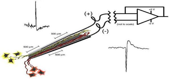
Schematic representation of the NE's electronic configuration. See text for description.
This unique design ought to provide for long lasting recordings that are stable. Longevity is due to the fact that the electrode tip incorporates itself into the brain via tissue growing through the hollow cone tip yielding no strain on the tissue. Thus it is no surprise that the electrode has continued recording for the lifetime of the implant, which has been as long as 15 months in the monkey (Kennedy et al, 1992a,b), 16 months in the rat (Kennedy, 1989), and over four years in humans (discussed in this paper). Without exception, the system was recording at time of damage to the implant or death of the subject. This is not to claim there were no problems. The monkeys invariably managed to damage the implants. The rats usually lived a full lifetime having been implanted at 3 to 4 months of age and dying a natural death or being euthanised at age 12 to 18 months. The humans died from their underlying diseases. Two subjects inadvertently damaged the implants (JR, ER) mainly due to spasms, but only replacement of the electronics was needed. In one subject, the incision could not be fully closed and it was removed after a few months before adequate data could be recorded. The electrode is designed for implantation for a human lifetime, and though obviously this has not been achieved yet, there is no apparent reason why it should not be. Encouraging in this regard are the electrodes made between 1986 and 1992: recent examination and manual strain testing show they are still intact after 15 to 20 years. A caveat, however, is the great difficulty in histologically reconstructing the recorded tissue. Thus, this electrode should not be used where histological reconstruction is required.
Recent developments and refinements of this system are presented in these two papers. The present paper details the techniques for electrode assembly, subject selection, target selection, electronic assembly and surgical implantation of this recording system. The second paper describes noise minimization, unit sorting and statistical data along with functional data in humans supporting the claims of signal stability and longevity.
2. Methods
2.1 Electrode assembly
The basic format of the electrode lying within cortical tissue is shown in Fig. 2. The six layers of cortex are diagrammed with the electrode tip in position near layer five that contains corticospinal tract cell bodies. Neurites are shown growing into the tip, through the cone, and out the top end so as to hold the glass cone tip in position. The tip is introduced at an angle of 45 degrees from the surface of the cortex, and inserted for a distance of 5 to 6 mms until the part of the wire on the surface of the cortex limits its insertion depth. The wire is brought along the surface and then rises above it with continuous coiling until it reaches its connector on the skull. The coiling provides strain relief in the X,Y and Z dimensions, operating like a ‘slinky’ toy that can move side to side in any direction as well as in and out. The inset shows an actual four wire glass cone tip. The scale bar is 0.5 mm.
Figure 2.
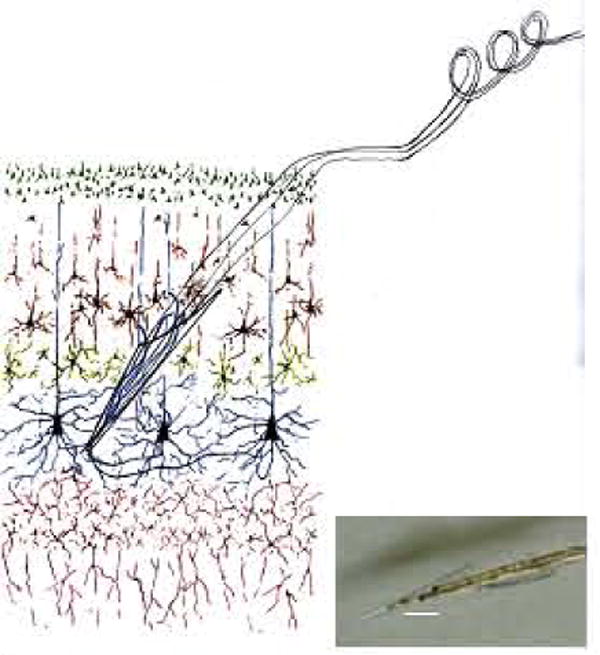
The NE in its intended placement in layer V of the neocortex. The inset photograph shows the NE tip with four wires inside. The scale bar is 500 microns.
The electrode consists of coiled gold wires with a glass cone tip on one end and a connector on the other. Initial attempts at assembly produced only one wire inside the cone, then two, now we have three wires in an implanted subject, and have produced four wire versions of the electrode as shown in the inset of Fig. 2. Other recent improvements include smaller connectors, specifically those from Omnetics Inc.'s Nanoconnectors series. We describe here the complete method updated from our original description in 1989 (Kennedy).
Assembly of the four-wire version is usually begun by taking a long length of 2 mil Teflon coated gold wire (California Fine Wire Inc., Grover Beach, CA 93433). The length of each wire is estimated by multiplying the final length by four. Therefore if a one-inch electrode is required, 16 inches of wire are used, 4 inches by 4 wires. This is first coiled on a hand wound mandrill as shown in Fig. 3. Next, the lower (cone) end is bent at 45 degrees and then a second bend is added at 45 degrees in the opposite direction as shown. These bends limit the possible implantation depth as shown in Fig. 4. The final bend at 45 degrees aims the wire into the cortex at the correct 45 degrees angle.
Figure 3.
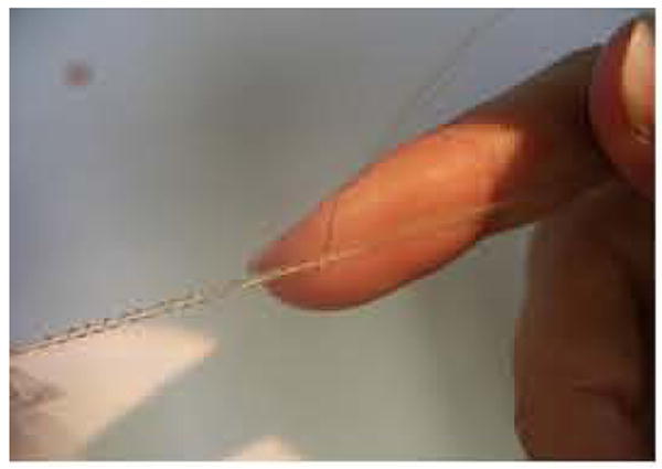
Photograph of four gold wires hand coiled for strain relief.
Figure 4.
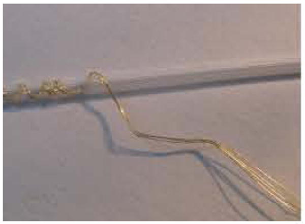
Forth-five degree bends in coiled wires that limit depth of cone tip insertion.
Next the connector is soldered onto the wire ends. A small load of solder is applied to the pin connectors. The wires are bared for 2 - 3 mm by scraping away the Teflon coating with a curved-edge scalpel. The bare end is placed against the pin loaded with solder and heated until the solder is seen to begin to melt. The heating iron must be rapidly removed to avoid melting back the gold wire. The solder will envelope the gold wire end. Finally, a coating of dental acrylic is applied to the connections to protect them from trauma. In the latest version of the electrode we are using Nanoconnectors from Omnetics Connector Corporation (7260 Commerce Circle East, Minneapolis MN - 55432). An example of these tiny connectors with acrylic covering the wires is shown in Fig. 5. A further example is shown with two coiled wires in Fig. 6.
Figure 5.
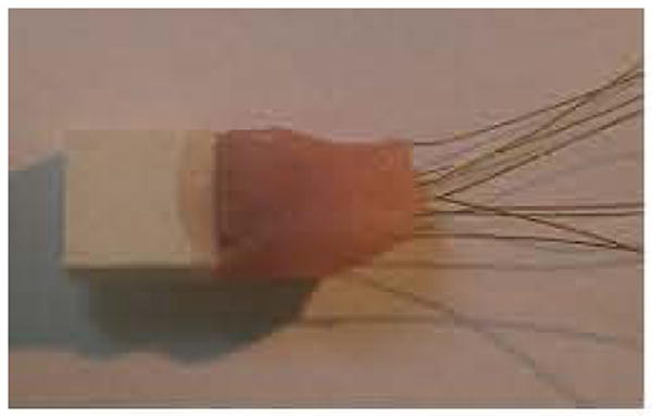
Omnetics connector with eight wires covered with acrylic cement for insulation.
Figure 6.
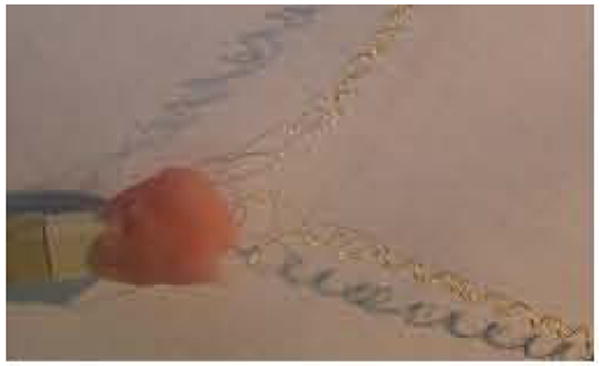
Omnetics connector with two sets of four coiled wires with connections covered in acrylic.
The next step is to manufacture and attach the cone. The glass cone is shaped by heating and pulling a thin walled borosilicate microfilament glass rod of wall thickness 0.125mm and diameter 1 mm (AM Systems Inc., 1220 75th St. S.W., Everett, WA 98203). The electrode puller (model 720 from Kopf, Tujunga, CA) has settings of 12.5 for the heater and 1.0 for the solenoid that applies the pull. The lower end of the cone is shaped by breaking the tip with forceps until the tip diameter is 50 to 100 microns. The upper end is shaped by using a diamond knife to cut the glass. Prior to cutting, a piece of fine wire (one strand of a stainless steel wire) or fine hair (from your head) is inserted into the lower end of the cone so that when it is cut off and moves away from the glass rod, the wire or hair “handle” can be used for easy retrieval with fine forceps. The upper end is broken back with forceps until it measures about 300 - 400 microns in diameter, and has a shelf extension. The covered area of the electrode should be about 1 to 1.5 mm. The final result is shown in Fig. 7 with the hair inside. Scale is in mms. Fig. 8 shows another view of the final curvature of the wires. Note that the section parallel to the table surface lies along the surface of the brain after implantation and limits the depth of implantation of the tip.
Figure 7.
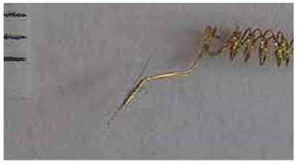
Glass cone tip is maneuvered onto three gold wires using a pience of hair as a “handle”.
Fignre 8.
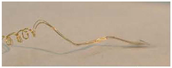
View of the glass cone tip containing four wires.
To attach the cone to the four gold wires, the wires are first attached together by placing a dab of glue along their lengths near the bends. The wires are trimmed with a new blade by cutting across their ends at an angle after the glue has been used to keep them together. The exposed surface is over 50 microns in diameter and produces an impedance of 1000 kohms or less when measured with a 1 kHz AC current. This impedance drops over the initial weeks of implantation as discussed below. The final step is to fix the wires inside the cone. The cone is manipulated by holding it with the inserted wire or hair. It is approximated to the four wires until they are all inside. Fixation is achieved by applying the methylmethacrylate gel glue to the wires and cone. The shelf is very useful in this regard because it allows a large surface for fixation. This minimizes the possibility of glue covering the tips of the wires. The glue is applied in stages with each stage drying overnight until the gold wires and shelf are completely covered with glue. This is shown in Fig. 9 where the ‘bump’ in the wires at the entrance to the glass cone is the heaped-up glue. Note the shadow showing the reflection of the wires (there are actually four in the cone tip even though it looks like three). The tip is somewhat larger than normal for illustration purposes, measuring four mms from tip to apex of the shelf.
Figure 9.
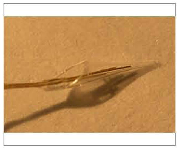
The cone tip has a shelf for gluing wires securely into position.
The new Omnetics 8 pin connectors (white) are much smaller in volume compared with the standard connectors presently in use, as seen in Fig. 10. Finally, a handle is made by soldering larger diameter wires to a plug that inserts into the electrode connector. This allows for easy handling of the delicate electrode. The handle, shown in Fig. 11 as three colored wires plugged into the electrode's connector, is itself connected to plugs fixed to the bottom of a sealed container. The container allows safe storage and transport prior to sterilization and implantation. The figure's scale is in mms. Sterilization is achieved using gluteraldehyde gas sterilization at low temperature setting. One week must be allowed for aeration. Vacuum aeration will damage the electrode, as will a high heat setting, by weakening the methylmethacrylate glue. Steam sterilization is avoided for the same reason.
Figure 10.
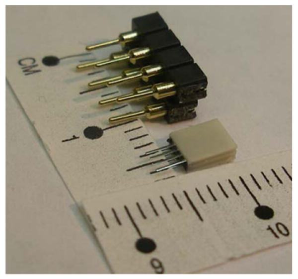
Image of old and new 8 pin connectors showing the dramatic reduction in size.
Figure 11.
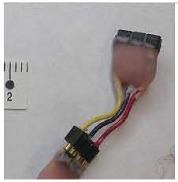
A handle is used to maneuver the finished electrode at surgery.
2.2 Patient selection
Once the subject has expressed a desire to participate, the most important criterion for selection does not concern the subject: it is the family caregivers. The subject will not succeed if the caregivers provide no, or poor, support. Secondly, the subject should be medically stable, that is, free from bedsores, recurrent infections of teeth, gums, chest, urinary tract and so on. Thirdly, the subject should want to communicate and be willing to work at the research effort. In our present project where we are trying to restore conversational speech, we are obliged by the FDA to choose someone who is locked-in and yet has normal speech areas in functional imaging along with normal cognition and alertness. Some form of communication, often just a slight eye movement, is sufficient to provide a ‘yes’ answer. We test cognition by asking simple questions in a conversational way and expect appropriate ‘yes’ (or if possible ‘no’) answers. For example, we show the subject a picture of a blue sky. When asked “Is the sky blue?” and the answer given is ‘yes’, then the subject is asked “Is the sky green?” If the answer is ‘yes’, we clearly have a problem with cognition. In addition, we always require a normal Electroencephalogram (EEG). Recently, we have obtained a quantitative EEG (qEEG) that provides a measure of coherence and functionality of the cerebral hemispheres. Next we obtain a Magnetic Resonance Image (MRI) of the brain that must show anatomically intact hemispheres. We then obtain functional MRIs to determine if there are areas suitable for implantation as explained in the next section. In the case of ALS subjects, we usually obtain Magnetic Resonance Spectroscopy to determine the metabolic state of the brain.
2.3 Target Localization using fMRI
In preparation for electrode implantation, the subject undergoes functional brain mapping using functional Magnetic Resonance Imaging (fMRI) to determine the optimal implant target. The technique used here is the BOLD wherein brain activity is detected using an endogenous paramagnetic contrast agent, deoxyhemoglobin. Neuronal activity induces changes in regional cerebral blood flow (rCBF), blood volume (rCBV) and blood oxygenation which lead to the change of deoxy-hemoglobin concentration. As a result, MR signal of the surrounding brain tissue varies with the change of the deoxyhemogloin concentration. Fig. 12 shows brain activation induced MRI signal changes responding to a stimulation paradigm, obtained at a typical clinical MRI setting, i.e, 1.5 Tesla scanner and a spatial resolution of approximately 4 mm in a patient with a brain tumor. Details of the method and results of this technique in our subject group are being published separately.
Figure 12.
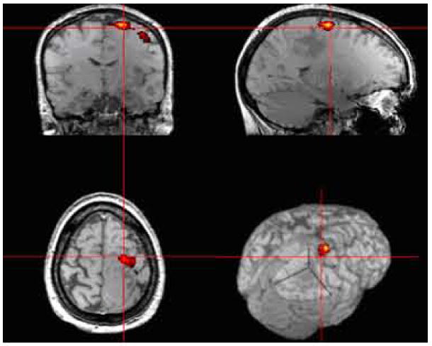
Example, of high resolution presurgical fMRI mapping of the motor area in a patient with brain tumor.
2.4 Implanted Electronics
A functional diagram of the implant electrode and the telemetry system is shown in Fig. 13. As mentioned above, the Neurotrophic Electrode can be fabricated with one, two, three, or four wires. The circuit diagram shows a three-channel configuration. The design utilizes standard surface mount electronic components mounted on a thin printed circuit board. The system employs a low noise instrumentation amplifier to provide differential amplification of the signals between the recording electrodes. The amplified signal is passed through an analog switch. When power is first applied the analog switch selects the output of a calibration signal. The amplitude of this 1 KHz signals has been calibrated to be equivalent to a 50uVpp signal at the input to the amplifier. The calibration tone provides a means of calibrating the channel gain through the FM modulation and demodulation process. The tone also indicates correct FM tuning. The electronics are powered by a power induction system operating at 1 MHz. A magnetic field is induced using a coil on the scalp and a resonant coil inside the implanted electronics converts the magnetic field to current. The current is rectified and the voltage is filtered and regulated to provide a bipolar supply for the differential amplifiers, calibration signal generators, and FM transmitters. The outputs of the FM transmitters are demodulated using a commercial computer controlled FM receiver (WinRadio Inc). The input to the FM receiver is a coil antenna that is placed on the head near the FM transmitters. The output of the FM receiver drives the data recording and analysis system.
Figure 13.
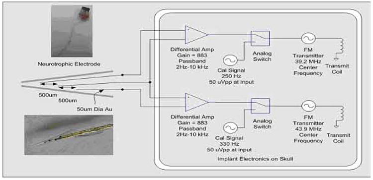
Implanted Neurotrophic Electrode and telemetry system.
There are currently three coatings applied to the electronics - Parylene, Elvax, and Silastic - to protect the electronics from fluids while under the scalp and to make the package biocompatible. After the coatings are applied, the devices are soaked in saline and then bench tested to verify continued performance. These soak tests are performed for weeks or months before implantation.
2.5 Surgical Implantation Technique
Immediately prior to surgery, an anatomic MRI is performed with fiducial markers in place on the scalp. After general anesthesia and stabilization of the head, the 3D frameless stereotaxy system is used to localize the target and hence determine the final location of the scalp incision. After standard sterilization of the skin, the scalp is incised and craniotomy performed. The brain is exposed after opening the dura and the final gyral target is localized using the frameless stereotaxy system again. The implant site is identified with reference to the fMRI data. Proprietary trophic factors fill the Neurotrophic Electrodes (NEs) that are approximated to the cortex whose pia has been incised. Commercially obtained Nerve Growth Factor (NGF) has been used in rats and monkeys. It is guided into position under the microscope to a depth of 5 to 6 mms below the cortical surface at an angle of 45 degrees to the planar surface of the gyrus. The outer (or upper) end of the glass tip is pushed below the surface and then covered with gelfoam until the craniotomy opening is a bed of gelfoam. This is covered with acrylic cement after the NE connectors have been connected to the electronics. This is shown in Fig. 14 where the attached silastic coated electronics are shown on the left, the acrylic cement covering the connector is shown below, and the tiny electrode wire may be visible at dead center. To the right are pieces of gelfoam which are used to make a final cover after the dural edges have been approximated. The subject's nose is to the right, and the left ear is upwards. All is covered with acrylic and the wound is closed in layers. A drain is usually not utilized.
Figure 14.
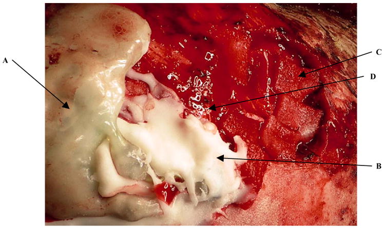
Surgical implant site shows electronics (A), cement (B) and gelfoam (C). The nearly invisible electrode coils are dead center exiting from the cement and running upwards (D).
3. Results
3.1 Electrode assembly
The various assembled electrodes are shown in Fig. 15. The top panel, shows (on the left) an original single wire electrode from 1986 for rat implantation that is still intact more than 20 years after manufacture. The glass tip was stressed by manually pushing on it multiple times with a forceps and it did not detach from the wire. The next electrode was manufactured in 1990 and is a double wire electrode. Its tip is still intact. The 2000 electrode is a longer, three-wire electrode and is for use in human cortex. The three-colored wire extension is a temporary ‘handle’ for ease of handling especially at surgery (as described in the Methods section). The 2006 electrode is a four-wire version for human implantation. Note also the longer length of the final wires carrying the glass cone tip. The final electrode dated 2007 is a pair of four-wire electrodes recently assembled and attached to a miniature Omnetics connector.
Figure 15.
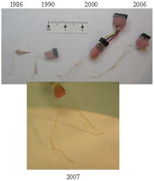
Evolution of completed electrodes from 1986 to 2007.
3.2 Patient selection criteria
Using the criteria described in methods, we have implanted eight subjects since 1996, five with the Neurotrophic Electrode (NE) and three with extradural electrodes (EDEs) (stainless steel skull screws). These EDEs improved the signal to noise ratio of EEG signals and were used for single electrode EEG communication systems (Kennedy et al, 2004). The results with the five subjects implanted with the NE along with the three subjects with EDEs are shown in Table I in chronological order of implantation.
3.3 Target selection
Using a confrontation naming task that we developed and tested in healthy volunteers we were able to detect robust activation in the motor speech area of our present locked-in subject ER in preparation for electrode implantation (Fig. 16). We believe that this is the first time a direct BCI has been established in the frontal regions using signals generated from the motor speech area as shown in Fig. 17. We have used this technique in all patients implanted and in some patients who were assessed but not implanted. The speech area has been located in three subjects (ER, DD and EM (not implanted)).
Figure 16.
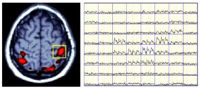
BOLD MRI signal time courses in pixels within a Region of Interest (yellow box) of left pre-motor area, depicted the activation signal pattern in activated pixels while non-activated pixels remained at the baseline. The fMRI exam task was to imagine right-handed finger movements in a block design with 3 ON and four OFF periods (30 seconds/block).
Figure 17.
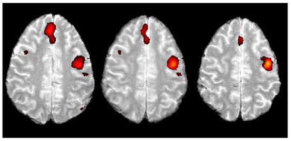
Area in the left superior frontal gyrus was activated in the confrontation naming task in our present subject ER.
3.4 Implanted Electronics
The electrode and the electronics have been successfully implanted in five patients. The most recent, subject ER, was re-implanted with the electronics on February 2005 (Fig. 18) and again in August 2007. His electronics were accidentally traumatized. His is a 3-wire Neurotrophic Electrode with two amplifiers, with the center wire acting as reference for each amplifier as shown in Fig. 13.
Figure 18.
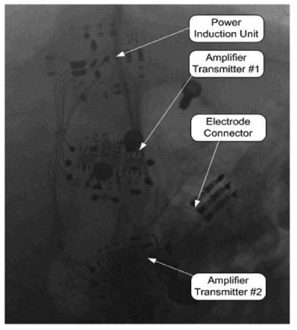
X ray Image of Implanted Recording Electronics
3.5 Surgical Implantation and Recording system
Implantation was performed as described in Methods. Fig. 19 is derived from a 3D computerized tomographic scan of the left side of the subject's head taken almost two years after implantation. His nose is to the left. The electronics are on the vertex, and the craniotomy is in the center. A ‘hook like’ structure can be seen traveling down from the electronics into the craniotomy opening. This is the coiled wire of the electrode and is positioned exactly as targeted implying that the electronics and electrode were surgically implanted as planned according to the fMRI study.
Figure 19.
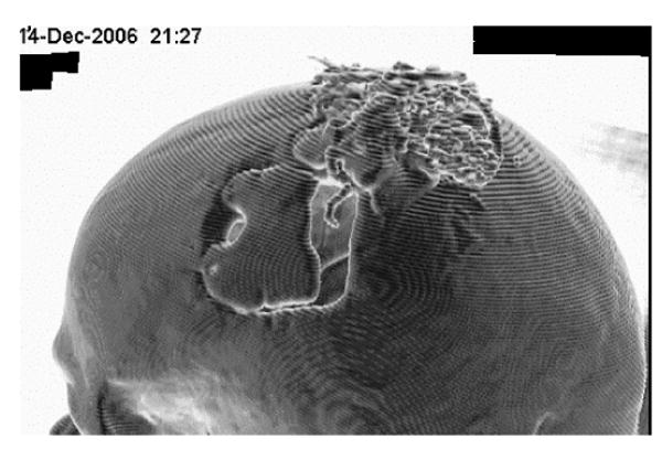
3D CT scan of ER with electronics (on vertex) and electrode wire (center of craniotomy opening) two years post implantation.
4. Discussion
This paper describes an updated and detailed assembly of the Neurotrophic Electrode in its new miniature version. This version includes a miniature connector with eight leads and a tip that contains as many as four wires inside, all assembled under the microscope. The archived single and double wire electrodes assembled in 1986 through 1992 are still available for comparison. The present electrodes with three or four recording wires allow identification of many more signals than before, as described in the companion paper. This is an obvious advantage over the previous versions. The reason that many more electrodes are not implanted is because of space limitation of the electronics, not the electrode. As discussed in the companion paper, there is a spatial resolution, approaching 600 microns, from which the signals are extracted. Electrodes could be placed within a few millimeters of each other, but the limiting factors are the implantable electronics.
The implantable electronics are bulky as can be seen in Figs. 14 and 19. We cannot place more than four on the skull, and usually we place two as shown in Fig. 19. We intend to miniaturize these so as to provide at least 16 amplifiers, and possibly a multiple of that number, so that there will be no theoretical limit to the number of electrodes that can be implanted. The problem of connecting to the electrodes is a separate problem that must also be solved before the number of implantable electrodes can be increased. The implanted electronic module is coated with Parylene, Elvax, and Silastic for sealing and biocompatibility. The coatings cannot withstand severe blows as we have found, and instead of replacement following damage, one solution is to cover them even more completely with acrylic or use a ceramic or titanium casing for rigidity. A major advantage of the power induction system is that the lack of a battery extends the implant life since there is no need to change a battery. Another problem is the attachment of the receiving coils to the subject's scalp during recording sessions. The recent advent of a non-toxic EEG paste has solved this problem and allows firm adhesion of the coils to the scalp even during spasms.
Target localization using fMRI during our confrontation-naming task reveals activation of the motor speech area. Improvements in localization of specific functions, such as phonemes for speech localization, or digits for movement tasks, will allow more targeted implants. These improvements will be aided by the advent of more powerful magnetic resonance scanners, and knowledge of (1) specific functional localizations and (2) the paradigms required to evoke activity in these localizations.
The multiple steps involved in the electrode assembly, electronic assembly, target localization and implantation require a high level of skill. Assembling the electrode requires hours of manipulation at a microscopic level. The final NE is extremely fragile and must be carefully handled and stored. Assembly and testing of the implantable electronics also require a high level of experience. Final placement of the NE and electronics are critical to the unit's performance, and the neurosurgical implantation requires a high level of skill. Despite these difficulties, the NE ranks above all other electrodes for longevity and stability of recorded signals (Anderson and Bruneo, 2002; Carmena et al, 2003; Serruya et al, 2002; Taylor et al 2002). There are three major categories of electrodes for cortical recording: 1: Those made with tines; 2: Those made with wires; and 3: Those made with a glass tip bathed in trophic factors on wires (the NE is the only electrode currently configured in such a manner). One major aim of recording from human cortex is restoration of environmental interaction to paralyzed patients, whether that interaction is physical or verbal. There are certain criteria on which to judge an electrode's performance. Kennedy (2006) enumerates these features in the Biomedical Engineering Handbook as longevity, stability, plasticity, directionality, force, local field potentials (LFP), units per contact, units per electrode, EMG relationship, and ability to safely and effectively stimulate the underlying neuropil. The paper claims that longevity and stability are prime characteristics of the Neurotrophic Electrode. The data in support of that contention are presented in a separate paper to be published elsewhere.
Table I.
| Subject | Age, Implant Date | Disease | Electrode Type | Recording Duration post implant | Function Achieved | Data Type |
|---|---|---|---|---|---|---|
| MH | 38, 12/4/1996 | ALS | NE | Till death @ 76 days | Binary control of activity | 9 APs |
| JR | 52, 4/24/1998 | BSS | NE | Till death @ 4 years | Controlled cursor & cyber hand; velocity relationships | 19 APs 2 LFPs |
| TT | 39, 7/19/1999 | MM | NE | Cognitive decline; died @ 4.5 yrs | Poor control due to degraded cognition | 2 APs 2 LFPs |
| GT | 68, 11/18/2001 | ALS | EDE | Till death @ 4 weeks | Died in sleep, too soon for data | 2 LFPs |
| RR | 43, 2/14/2002 | ALS | EDE | Till death @ 6 weeks | Controlled switch with LFP | 2 LFPs |
| DJ | 41, 10/25/2002 | ALS | NE | Two sessions | APs, LFPs, EMG & movement | 8 APs 2 LFPs |
| DD | 43, May 2004 | ALS | EDE | Over 12 months, living | Answered ‘yes’ or ‘no’ | 1 LFP |
| ER | 23, 12/22/2004 | BBS | NE | Continues March 2007 | Produces seven phonemes or short words | 42 APs |
ALS = Amyotrophic Lateral Sclerosis or Lou Gehrig's Disease. NE = Neurotrophic Electrode. AP = action potential. BSS = Brainstem stroke. LFP = Local Field Potential. MM = Mitochondrial Myopathy. EDE = Extradural Electrode. EMG = Electromyographic activity.
Footnotes
Publisher's Disclaimer: This is a PDF file of an unedited manuscript that has been accepted for publication. As a service to our customers we are providing this early version of the manuscript. The manuscript will undergo copyediting, typesetting, and review of the resulting proof before it is published in its final citable form. Please note that during the production process errors may be discovered which could affect the content, and all legal disclaimers that apply to the journal pertain.
References
- Andersen RA, Buneo CA. Intentional maps in posterior parietal cortex. Annual Rev Neurosci. 2002;25:189–220. doi: 10.1146/annurev.neuro.25.112701.142922. [DOI] [PubMed] [Google Scholar]
- Carmena JM, Lebedev MA, Crist RE, O'Doherty JE, Santucci DM, Dimitrov DF, Patil PG, Henriquez CS, Nicholelis MAL. Learning to control a brain-machine interface for reaching and grasping by primates. PloS Biology. 2003;1(2):193. doi: 10.1371/journal.pbio.0000042. [DOI] [PMC free article] [PubMed] [Google Scholar]
- Kennedy PR. A long-term electrode that records from neurites grown onto its recording surface. J Neuroscience Methods. 1989;29:181–93. doi: 10.1016/0165-0270(89)90142-8. [DOI] [PubMed] [Google Scholar]
- Kennedy PR. Comparing electrodes for use as cortical control signals: Tiny tines, tiny wires or tiny cones on wires: Which is best? In: Brazino Joe., editor. The Biomedical Engineering Handbook. Third. 2006. pp. 32.1–32.14. [Google Scholar]
- Kennedy PR, Andreasen D, Ehirim P, King B, Kirby T, Mao H, Moore M. Using human extra-cortical local field potentials to control a switch. J Neural Eng. 2004;1:72–7. doi: 10.1088/1741-2560/1/2/002. [DOI] [PubMed] [Google Scholar]
- Kennedy PR, Bakay RAE. Restoration of neural output from a paralyzed patient using a direct brain connection. NeuroReport. 1998;9:1707–11. doi: 10.1097/00001756-199806010-00007. [DOI] [PubMed] [Google Scholar]
- Kennedy PR, Bakay RAE, Sharpe SM. Behavioural correlates of action potentials recorded chronically inside the cone electrode. NeuroReport. 1992a;3:605–8. doi: 10.1097/00001756-199207000-00015. [DOI] [PubMed] [Google Scholar]
- Kennedy PR, King B. Dynamic interplay of neural signals during the emergence of cursor related cortex in a human implanted with the Neurotrophic Electrode. In: Chapin J, Moxon K, editors. Neural Prostheses for Restoration of Sensory and Motor Function. Ch 7. CRC Press; 2001. [Google Scholar]
- Kennedy PR, Mirra S, Bakay RAE. The cone electrode: Ultrastructural studies following long-term recording. Neuroscience Letters. 1992b;142:89–94. doi: 10.1016/0304-3940(92)90627-j. [DOI] [PubMed] [Google Scholar]
- Serruya MD, Hatsopoulos NG, Paninski L, Fellows MR, Donoghue JP. Instant neural control of a movement signal. Nature. 2002;416(6877):141–2. doi: 10.1038/416141a. [DOI] [PubMed] [Google Scholar]
- Taylor DM, Tillery SI, Schwartz AB. Direct cortical control of 3D neuroprosthetic devices. Science. 2002;296(5574):1829–32. doi: 10.1126/science.1070291. [DOI] [PubMed] [Google Scholar]


