

Abstract
We have designed and built a small animal single photon emission computed tomography (SPECT) imaging system equipped with parallel-hole and multipinhole collimators and capable of circular or helical SPECT. Copper-beryllium parallel-hole collimators suitable for imaging the ~35 keV photons from the decay of 125I have been built and installed to achieve useful spatial resolution over a range of object-detector distances and to reduce imaging time on our dual-detector array. To address the resolution limitations in the parallel-hole SPECT and the sensitivity and limited field of view of single-pinhole SPECT, we have incorporated multipinhole circular and helical SPECT in addition to expanding the parallel-hole SPECT capabilities. The pinhole SPECT system is based on a 110 mm diameter circular detector equipped with a pixellated NaI(Tl) scintillator array (1×1×5 mm3/pixel). The helical trajectory is accomplished by two stepping motors controlling the rotation of the detector-support gantry and displacement of the animal bed along the axis of rotation of the gantry. Results obtained in SPECT studies of various phantoms show an enlarged field of view, very good resolution and improved sensitivity using multipinhole circular or helical SPECT. Collimators with one, three and five 1 mm diameter pinholes have been implemented and compared in these tests. Our objective is to develop a system on which one may readily select a suitable mode of either parallel-hole SPECT or pinhole circular or helical SPECT for a variety of small animal imaging applications.
Keywords: SPECT, multipinhole, helical, small animal imaging
1. Introduction
Among modern nuclear imaging techniques, single photon emission computed tomography (SPECT) has shown considerable promise in small-animal imaging for biomedical studies and has given rise to improvements in detectors, scintillators, collimator design, and image reconstruction techniques. Requirements of spatial resolution, sensitivity and image quality are quite challenging for the development of imaging systems for small animals. The capabilities of the system are significant for carrying out small animal imaging in a wide range of biological studies. Moreover, compactness, economy and expandability of the system need serious consideration. A review of recent reports shows that significant progress has been made in achieving these goals with custom-made or commercial systems incorporating various modes of SPECT imaging. Of particular interest is recent work on applications of multipinhole SPECT [1–17] and helical SPECT (HSPECT) [18–27].
Several groups have demonstrated the feasibility of multipinhole SPECT in small animal imaging. Schramm and Lackas and collaborators in a series of papers [1–8] presented a multipinhole SPECT system based on commercial gamma cameras and dedicated multipinhole collimators with high resolution as well as superior sensitivity. Bioscan [9] is now providing commercial NanoSPECT/HiSPECT systems based on their work. Meikle et al. [10–12] reported on a coded multipinhole SPECT system suitable for certain high-resolution imaging applications in small animal studies. Beekman et al. [13–15] proposed a novel stationary U-SPECT system incorporating multipinhole collimation without multiplexing. The U-SPECT-I system (in which “U” stands for ultra-fast, ultra-sensitive and ultra-high resolution) incorporates 75 gold pinholes and standard NaI detectors. Their U-SPECT-II/CT system is commercially available now with even better performance. Goertzen et al. [16] designed and constructed a multipinhole SPECT system with a stationary clinical scanner and a rotating collimator, which efficiently balanced the resolution and sensitivity showing considerable potential for dynamic imaging of small animals. Peterson et al. [17] reported the development of a fully customized multipinhole SPECT system equipped with silicon strip detectors. The results from their prototype system proved its feasibility for small field-of-view studies such as the mouse brain.
To solve the problem of axial blurring of circular-orbit pinhole SPECT, Metzler et al. [18–22] reported the application of the helical orbit conventionally used in transmission computed tomography to imaging with SPECT. Sun et al. [23] presented a helical SPECT scanner featuring solid-state cadmium zinc telluride (CZT) detectors. Their initial results demonstrated improved axial spatial resolution and field of view (FOV). Hwang et al. [24] were building a dual-modality system incorporating X-ray CT and microSPECT capable of helical imaging. Zeng et al. [25–27] performed helical-orbit SPECT with various collimators and proved that a sufficient helical orbit pitch would facilitate SPECT imaging of the entire mouse body.
Because of the limited longitudinal field of view of multipinhole SPECT and the low sensitivity of single pinhole helical SPECT, interest has recently arisen in combining multipinhole SPECT with a helical orbit. Lackas et al. reported an “on-development” system capable of multipinhole helical SPECT. They have presented simulation results demonstrating the improvement in axial image quality resulting from use of a helical orbit [6]. However, multipinhole helical SPECT needs further study for small animal imaging.
Despite the advances of pinhole SPECT, parallel-hole SPECT imaging is still an important tool for biomedical studies of small animals because it provides high efficiency and acceptable resolution over a relatively large active area. Parallel-hole planar imaging is especially valuable for whole animal region of interest (ROI) quantitative analysis and distribution studies. Incorporation of parallel-hole imaging capability in an imaging system will certainly provide researchers an alternative efficient tool for biological studies as evidenced by a number of recent reports [e.g. 28,29].
A primary goal in this work has been to develop a compact small animal imaging system that incorporates both multipinhole circular and helical SPECT and parallel-hole SPECT building upon reports by others as mentioned above and our previous studies [28–33]. In using this system, one may readily select one of these modes according to the different requirements for a variety of small animal imaging applications. We have recently reported the development of a high-performance compact gamma camera suitable for parallel-hole planar or SPECT imaging [29]. However, we find a significant reduction in spatial resolution when an object is positioned farther from the detector surface. In addition, use of a single detector limits the ability to carry out short-term SPECT imaging. In this work, we have addressed those issues by adding a second compact detector with a newly designed collimator. We have also extended the capabilities of our system by incorporating multipinhole circular and helical SPECT. Another goal of this work is to evaluate the feasibility of multipinhole helical SPECT for small animal imaging. Using phantom studies we report here the efficiency, FOV and reconstruction resolution for the multipinhole circular and helical SPECT.
2. Equipment and Methods
A. System Design
The system was constructed in a compact fashion suitable for a range of imaging applications using 125I. As there are hundreds of iodine-tagged ligands available commercially, 125I continues to be an important radiotracer in biological research, easy to employ and readily available. There is a large body of research already conducted with 125I compounds thus providing an important baseline for future imaging studies. 125I emits a ~35 keV gamma-ray and/or 27–32 keV X-rays. The low emission energy and the reasonably long half-life (59.4 days) make it an efficient tool for in vivo animal imaging, particularly for imaging a small animal over more extended periods of time.
A total of four gamma-ray detectors, two “mouse-sized” compact cameras and two 110 mm diameter circular detectors, were mounted on a cylindrical gantry as shown in Fig. 1. As mentioned above, parallel-hole imaging is still a useful tool and has distinct advantages in biological studies. For these purposes, the set of “mouse-sized” compact cameras (#1–2) and one of the 110 mm diameter circular detectors (#3) were equipped with parallel-hole collimators designed for 125I imaging [29,30,32]. Previously, we reported the development of one such compact gamma camera (#1) for biological imaging [29,30]. To reduce SPECT imaging time, a second compact gamma camera (#2) has been built and installed on the gantry to provide a dual-detector array. A new CuBe parallel-hole collimator has been designed and manufactured to reduce the diminution of resolution with increasing source-to-detector distance.
Fig. 1.

Photograph of the compact parallel-hole and pinhole circular/helical SPECT imaging system. Signal processing and storage instruments are not shown in this picture. All detectors are incorporated in a cylindrical gantry capable of rotating 360 degrees. Detectors #1–2 are “mouse-sized” compact gamma cameras and detectors #3–4 are 110 mm diameter circular detectors.
A second 110 mm diameter circular detector (#4) was employed with pinhole collimation. This system design was aimed at the use of a relatively low dose of 125I while simultaneously achieving high-resolution imaging of small tissues such as the mouse thyroid with the potential for imaging an entire mouse. Therefore, we have designed a multipinhole collimator based upon the effective view area of this detector and the requirements for acceptable spatial resolution. We have also implemented a translation rack supporting the mouse bed along the axis of rotation (AOR) of the system so that a helical trajectory can be employed for improved sampling completeness and increased longitudinal field of view.
B. Cylindrical Gantry
The cylindrical rotating gantry measuring 110 cm in length and 45 cm in diameter holds a set of 110 mm diameter circular detectors, a set of 46×96 mm2 “mouse-sized” detectors and a Lixi fluoroscopic x-ray system (Lixi Inc.). Space exists for incorporation of additional detectors if needed. The gantry is driven by a stepping motor (200 steps per revolution) which can be controlled manually by a wired remote controller or automatically by a G3 Macintosh computer through the stepping motor driver Velmex NF90 (Velmex Inc.). The computer communicates with the driver via the RS232 interface. A 120 mm long Lexan tube placed horizontally at the center of rotation and in the field of view of both γ-ray detectors and X-ray fluoroscope facilitates the transfer of the animal among the various imaging devices while supporting a custom-made mouse bed. The support tube with ~1.5 mm thick wall absorbs only 7% of the 35 keV photons from 125I. Its transparency allows easy positioning and visual monitoring of the animal. The tube can also serve a dual purpose of keeping the animal in stable condition with introduction of humidified, warmed air from one end and preventing contamination of the environment by exhaust of gases from the other end via a tube leading to a filtered exhaust system [31].
C. Gamma Ray Detectors for Parallel-Hole Collimation
As mentioned earlier, two different size γ-ray detectors were incorporated in the system for parallel-hole imaging. One is a circular detector (#3 in Fig. 1) based on a Hamamatsu R3292 PSPMT with a diameter of 110 mm. A pixellated array of CsI(Tl) scintillators was air-coupled to the front window of the PSPMT. Each scintillation crystal measures 1×1×3 mm3 separated by 0.2 mm walls (Hilger Crystals, Westwood, England). A 3 mm thick parallel-hole CuBe collimator was employed with 0.2 mm square openings separated by 0.05 mm septa (Tecomet Inc., Woburn MA, USA). A full-width at half-maximum (FWHM) spatial resolution of 2 mm was achieved with this collimation for a source-to-collimator spacing of 5 mm [32].
A pair of “mouse-sized” compact detectors #1–2 in Fig. 1, each incorporating a pair of 50×50 mm2 square Hamamatsu H8500 PSPMTs, was installed on the gantry. The effective area of each of those detectors is approximately 46×96 mm2. For the previously developed compact detector (#1), the PSPMTs were optically coupled to a pixellated NaI(Tl) crystal array fabricated by Bicron/St. Gobain Inc., each crystal element measuring 1×1×5 mm3 separated by 0.2 mm reflective walls. A 5 mm thick CuBe collimator (Collimator #1) designed for imaging ~35keV photons emitted from 125I was employed with 0.55-mm square openings separated by 0.11 mm septa (Tecomet Inc., Woburn MA, USA). This collimation provides high efficiency imaging with a spatial resolution (FWHM) of about 2.5 mm at the collimator surface [29].
A second compact gamma camera #2 has been recently built and installed on the gantry to form a dual-detector array with the newly designed parallel-hole collimator. The new CuBe collimator (Collimator #2) measures 6 mm thick with 0.3×0.3 mm2 openings and 0.05 mm septa. Collimator dimensions were determined with the formulae of Keller [37] and Smith et al. [38] The efficiency and spatial resolution of the new compact gamma camera were measured with a single capillary phantom with an inner diameter of 0.3 mm containing an activity of 0.37 MBq in 8 cm length. The capillary phantom was imaged for 10 min at a distance 4 mm, 17 mm, 32 mm, 47 mm and 62 mm from the detector. The spatial resolution was obtained from the average of a Gaussian fit to three different one-pixel-wide slices across the line source. The theoretical resolution (Rs) was calculated based on the geometric resolution (Rg) of the collimator and the intrinsic resolution (Ri) of the detector, i.e. Rs2 = Rg2 + Ri2. Spatial resolution of the collimators was compared based on this new detector.
D. Gamma Ray Detector for Pinhole Collimation
A second 110 mm diameter circular detector #4 for pinhole imaging was installed on the gantry face to face with the first circular detector so that simultaneous gamma ray imaging with parallel-hole and pinhole collimation could be accomplished (Fig. 1). In this detector, a Hamamatsu R3292 module was air-coupled to pixellated NaI(Tl) scintillators measuring 1×1×5 mm3 with a 0.2 mm thick reflective separating walls. Shown in the left panel of Fig. 2 is the diagram of a five-pinhole collimator designed for imaging specific organs of small animals such as the mouse thyroid. A collimator of 1 to 4 pinholes can be effected by shielding the unused pinhole(s) with 0.5 mm lead sheet sufficient to block the 35 keV photons from 125I. Each pinhole in the 5 mm thick Cu collimator is 1 mm in diameter with a 0.2 mm knife edge and an opening angle of 90°. The collimator was 25 mm from the AOR of the gantry with a magnifying factor of 3 used in this work.
Fig. 2.

(Left) Diagram of the 5-pinhole collimator. (Right) Photograph of the setup to accomplish step-and-shoot helical orbit. Motor 1 controls the rotation of the cylindrical gantry round the AOR. Motor 2 controls the displacement along the AOR of the rack with a mouse bed fixed to one end.
E. Step-and-Shoot Helical Orbit
A circular orbit for imaging was effected by the stepping motor (Fig. 2, right; Motor 1) controlling the rotation of the gantry around the axis of rotation. By adding a second SLO-SYN stepping motor (Fig. 2, right; Motor 2, 200 steps per revolution, Superior Electric Inc.) to control the displacement of the mouse bed along the AOR, a helical orbit was accomplished for step-and-shoot imaging. The second motor drove a steel rack, on one end of which the mouse bed was fixed, through a spur gear as seen in the right panel of Fig. 2. A combination of the three components resulted in a stepping increment 1 mm per 10 steps along the AOR.
F. SPECT Runs and Image Reconstruction
Unless stated otherwise, every SPECT run in the following set of experiments was taken in 3° increments and with a 3 minute dwell time at each angular position. The approaches to image reconstruction were based on an iterative maximum likelihood-expectation maximization (ML-EM) algorithm. The modified EM algorithm by Green [34] was adopted for parallel-hole collimation. The reconstruction algorithm for pinhole collimation was extended from that described by Li et al.[35]. Siddon’s ray tracing technique was implemented in both cases [36]. A Hanning filter was employed for the reconstructed images. No attenuation correction was applied in this work. The reconstruction used cubic voxels with edge length 1.2 mm for parallel-hole collimation and 0.4 mm for pinhole collimation.
G. Experimental Design
Characterization comparison was carried out among single-, three-, and five-pinhole circular and helical SPECT. The central pinhole and the three pinholes on the diagonal of the five-pinhole collimator were employed respectively for single- and three-pinhole collimations by shielding the unused pinholes.
I. Field of View
In order to simplify the comparison of FOV for the multipinhole case, we compared the effective view area (EVA) in the plane passing through the AOR. The FOV of the corresponding collimation is simply the volume by rotation of the EVA around the AOR. The EVA of pinhole collimation was calculated based on the geometry of the pinholes with a magnifying factor of 3. The EVAs of three- and five-pinhole collimation were compared with single-pinhole collimation as reference. A 17.6×12.8 mm2 rectangular object big enough to cover the thyroid region of a mouse was simulated to calculate the multiplexing percentage that is the overlap area divided by the overall area of detector plane.
An experiment was carried out to demonstrate the extended field of view. Shown in Figure 4(a) is the phantom set up with three capillary tubes, each of which was 0.3 mm in inner diameter and contained 0.67 MBq 125I in 8 cm length. One capillary was put on the intersecting line of two perpendicular planes. A second capillary in one of the planes was parallel to it with 8.6 mm separation and a third one was in the other plane at an angle of 6.6 degrees. A 3-pinhole collimator was employed and helical SPECT was performed with an object translation step increment of 0.5 mm (the total movement along the AOR was 60 mm).
Fig. 4.

A 2 MBq three-capillary phantom study of 3-pinhole helical SPECT. (a) Setup of the phantom. (b) A 3-min projection. (c) Reconstructed slice 1. (d) Reconstructed slice 2
II. Efficiency
The efficiency of different modes of SPECT/HSPECT was determined by a phantom simulating the thyroid region of a mouse. The thyroid phantom measuring 15.9×15.9×15.9 mm3 contains three coplanar voids. The bottom two voids were separated by 3 mm representing the salivary glands of a mouse while the top one simulating the thyroid was spaced 2 mm away from them. The thyroid phantom contained a total of 0.56 MBq with 0.19 MBq in each void. The step increment of helical SPECT along the AOR was 0.1 mm with a total of 12 mm displacement for the entire imaging. The total counts of all the 120 planar images were collected and averaged over time and total dose to obtain the efficiency.
III. Resolution
Test scans of different modes of pinhole SPECT/HSPECT were carried out using the three-capillary phantom shown in Fig. 4(a). One of the capillaries was located 5.6 mm off the AOR and used to determine the reconstruction resolution (FWHM) of each mode of pinhole circular or helical SPECT. The step increment along the AOR was 0.5 mm for helical SPECT. Five transaxial images were reconstructed at different positions of the capillary for each scan. The intensity profiles along the line across the center of the reconstructed capillary region were then analyzed and fitted to Gaussian curves. Each FWHM was then calculated and the group corresponding to each SPECT mode was averaged to obtain the resolution of the mode. The relationship was evaluated between the reconstruction resolution and iteration number.
To demonstrate that the calculated reconstruction resolution is reasonable, we did three-pinhole helical SPECT of the capillary phantom shown in Figure 7(a), which was made with six glass capillary tubes placed side by side. The helical increment along the AOR was 0.5 mm per step. Each capillary contained ~0.37 MBq Na125I in 8 cm length. The diameter of each capillary was identical to that used for resolution measurements, namely, 0.3 mm in inner diameter and 1.45 mm in outer diameter. Therefore, the center-to-center distance of two adjacent tubes was 1.45 mm.
Fig. 7.

(a) A transaxial view of the phantom made with 6 capillary tubes placed side by side. Each tube contained ~0.37 MBq Na125I in 8 cm length. (b) A transaxial image of a 3-pinhole helical SPECT scan of the phantom. The step increment along AOR is 0.5 mm. (c) The profile of the six capillaries in the reconstructed image (b).
Performance of the imaging system was further evaluated using an ultra-micro hot spot phantom (Data Spectrum Co.) filled with 10 MBq Na125I, which had a radioactivity concentration of 2 MBq/ml. The phantom is 3.50 cm in outer diameter and about 5.5 cm in height. The rod insert is 2.7 cm in diameter with a height of 0.99 cm. The hot rod diameters of the six wedge-shaped regions in the insert are 0.75, 1.0, 1.35, 1.7, 2.0, and 2.4 mm, respectively. The center-to-center spacing of the rods in each wedge is two times the rod diameter. An additional ~ 1.3 cm thick plastic disk insert was used to reduce the total volume of solution required to fill the phantom. Helical SPECT scans using this hot-rod phantom were carried out with one or three pinholes with planar projections at 3° increments and 3 min/projection. The step increment was set to 0.1 mm considering the thickness (~ 10 mm) of the rod insert. Out of the 120 projections obtained in each scan, sixty projections with angular positions at 6° intervals were used to represent a three-hour helical SPECT scan with a step increment of 0.2 mm along the AOR. The time was chosen based on both our system design and a review of similar experiments reported by other researchers [6,10,13,39–40]. Images were reconstructed using 30 and 60 iterations for 1- and 3-pinhole helical SPECT, respectively. Reconstructed images with 4.4 mm total thickness are presented in Fig.8.
Fig. 8.

(a) A transaxial view of the hot-rod phantom using single-pinhole helical SPECT with 3° angular increments and 0.1 mm step increments along the AOR. Each of the 120 projections was 3 min/projection. The hot-rod phantom contained 10 MBq 125I with a concentration of 2 MBq/ml. The hot rod diameters of the six wedge-shaped regions in the phantom are 0.75, 1.0, 1.35, 1.7, 2.0, and 2.4 mm, respectively. (b) An image reconstructed from 60 slices out of those 120 projections to represent three-hour 1pHSPECT (c) One 3-min projection of the hot-rod phantom of a three-pinhole helical SPECT scan with the same imaging parameters as the 1pHSPECT scan. (d) A transverse image reconstructed from the 120 projections of the 3pHSPECT scan. Each reconstructed image presented here is 4.4 mm in thickness.
3. Results
A. Efficiency and resolution of the second compact gamma camera
The measured efficiency of compact detector #2 at 4 mm from the detector is 693 cps/MBq and 121 cps/MBq for 5 mm thick collimator #1 and 6 mm thick collimator #2 respectively. A plot is presented in Fig. 3 of measured detector spatial resolution (FWHM) vs. source-collimator separation. Overall, this result is in good agreement with theoretical predictions fitted with an intrinsic resolution 2.8 mm. That prediction takes into account the 3 mm thick optical glass windows of the scintillation array, the 2 mm thick PSPMT windows and an air gap of 3.2 mm between the collimator and scintillator. The difference between theoretical and experimental resolutions at a large distance from the detector for collimator #1 probably arises from the 0.3 mm inner-diameter capillary used for resolution measurement laying at a slant angle on the collimator with 0.55-mm square openings. As one may notice in Fig. 3, the advantage of collimator #2 is that it provides acceptable resolution 2.9 – 4.1 mm over a wide range (4 – 47 mm) of distance between the object and the detector. This is significant for SPECT scans because such a range in distance typically exists when imaging mice.
Fig. 3.

Comparison of spatial resolution with the newly constructed detector equipped with 5 mm thick high-sensitivity collimator #1 and 6 mm thick high-resolution collimator #2 respectively. Relatively high resolution was persevered over a useful range with the 6 mm thick collimator while the efficiency was lessened by a factor about 6.
B. Field of View
As shown in Table 1, three- and five-pinhole collimation have enlarged EVAs by 81% and 138% respectively compared to single-pinhole collimation. For a conventional circular orbit, however, one may readily show that the overall FOV is the same for both three- and five-pinhole case. The FOV of the helical mode is extended from its corresponding circular mode which eventually depends on the displacement of the detector along the AOR. By choosing a suitable step increment along the AOR, one expects the FOV of a helical mode to cover a specific region of interest or the entire body of the animal.
Table 1.
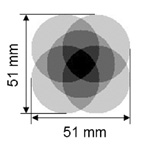
Characterization comparison among various modes of SPECT. One may note view area increase is over single-pinhole case. Multiplexing percentage is the overlap area divided by the detector plane with a simulated 17.6×12.8 mm2 rectangular object whose area is big enough to cover the thyroid region of a mouse.
| Collimator | Single-pinhole | 3-pinhole | 5-pinhole |
|---|---|---|---|
| Effective view area in the plane passing the AOR with magnifying factor 3 |  |
 |
 |
| View area increase |  |
81% | 138% |
| Multiplexing percentage |  |
9.5% | 20% |
| SPECT efficiency (cps/MBq) | 107 | 257 | 417 |
| HSPECT efficiency (cps/MBq) | 108 | 252 | 402 |
Shown in Fig. 4(b) is a typical 3-min projection of the phantom. Two transverse reconstructed slices are presented in figures 4(c)–(d). They were taken at positions separated by about 43 mm, which was larger than the 35 mm diameter of the EVA of the detector with a single pinhole. The capillaries in the reconstructed images are slightly non-circular owing to statistical effects.
C. Efficiency
As expected, the efficiency of pinhole circular SPECT is almost identical to that of short-range helical SPECT. Moreover, the efficiency of five-pinhole collimation is increased significantly to the level near that of parallel-hole collimation with the 5 mm thick high-sensitivity collimator #1, i.e. 693 cps/MBq, while the single-pinhole collimation shows relatively poor sensitivity.
D. Resolution
Presented in Fig. 5 is the plot of the overall reconstruction resolution as a function of ML-EM iteration number for various modes of pinhole circular/helical SPECT. Six sample profiles of the capillary in the transverse reconstructed slices after 13 iterations are presented in Fig. 6 corresponding to 1-, 3- 5-pinhole circular/helical SPECT respectively. Each profile was normalized to its peak value. The phantom of six capillaries placed side by side is shown in Fig. 7(a), followed by the reconstructed image presented in Fig. 7(b). Shown in Fig. 7(c) is the profile of the capillaries in the reconstructed image of a 3-pinhole helical SPECT scan. Each capillary can be resolved consistent with the calculated resolution.
Fig. 5.

Reconstruction resolution as a function of ML-EM iteration number for various modes of pinhole SPECT/HSPECT
Fig. 6.

Six profiles (a) – (f) of the capillary in the transverse reconstructed slices after 13 iterations for 1-, 3- 5-pinhole helical SPECT (a, c, e) and circular SPECT (b, d, f)
The reconstructed images of the hot-rod phantom are shown in Fig. 8 for single- and three-pinhole helical SPECT (1pHSPECT or 3pHSPECT). The image from six-hour 1pHSPECT can resolve the 1 mm diameter rods well and a few of the 0.75 mm rods. The image reconstructed from 60 out of the 120 projections of the six-hour 1pHSPECT scan reflects some noise owing to reduced statistics but still resolves the 1 mm rods.
Similarly, as shown in Fig.8(d), the reconstructed image of six-hour 3pHSPECT can also resolve 1 mm rods well and some of the 0.75 mm rods. The enlarged field of view using three pinholes facilitates reconstruction of the circular gap region in the phantom between the rod insert disk and the inner wall of the container. This hot circular region is only partially shown in single-pinhole cases. Some artifacts appear in the 3-pinhole cases mainly owing to the fact that there are always parts of the phantom truncated in projections through each pinhole as evidenced by a three-pinhole projection, Fig. 8(c). This results from the relatively large scale of the phantom contrasting somewhat with the main focus of the system design on imaging small organs of a mouse such as the thyroid with a magnifying factor 3. Multiplexing effects can be another factor contributing to artifacts. Results of both the single- and three-pinhole helical SPECT clearly demonstrate that the resolution we measured based upon fine capillaries containing high radioactivity concentration are also valid for a more conventional case in which a radioactivity concentration of a few MBq/ml of radioactivity is used in the hot rod phantom.
4. Discussion and conclusion
We have described the development of a compact gamma-ray imaging system incorporating circular and helical multipinhole SPECT and parallel-hole SPECT. The characterization of various modes of SPECT has been investigated using radioactive phantoms. As shown in Table 1., the diameter of the FOV of 3- or 5-pinhole circular SPECT is increased by a factor of ~1.5 compared with the single-pinhole case. The FOV is further increased in the longitudinal direction for multipinhole helical SPECT depending on the step increment along the AOR. The results show that the efficiency of the multipinhole system can be increased to a level comparable to parallel-hole collimation with a 5 mm thick collimator that provides high sensitivity with moderate resolution. Though at present the overall sensitivity is dependent upon the limited number of pinholes (up to 5) employed, we find that we have quite adequate sensitivity for a range of interesting biological studies.
The resolution comparison among pinhole SPECT/HSPECT shows that a reconstructed resolution of 1.2 – 1.5 mm can be achieved with this system. Both the profiles in Fig. 6 and the result of 3-pinhole helical SPECT of the six-capillary phantom in Fig. 7 demonstrate that the calculated FWHM resolution is reasonable. The results in Fig. 5 indicate there is no appreciable difference in the reconstruction resolution among one-, three- and five-pinhole SPECT using both circular and helical orbits. Referring to Table 1., the results further indicate that very good reconstruction resolution can be achieved with this system while the efficiency is enhanced substantially with an increase in the number of pinholes from one to five. On the other hand, we observe slower convergence of the ML-EM algorithm for multiple pinhole data than for a single pinhole in either the circular or helical case. There is also slight loss of reconstruction resolution with increasing iteration number. Both these results are consistent with the report of Meikle et al., whose simulation result of mean squared error versus iteration number indicated both slower convergence of the ML-EM algorithm for multipinhole SPECT and increased noise with increasing number of iterations [12].
The measured resolutions are further demonstrated by experiments using hot-rod phantoms. Results from both single- and 3-pinhole helical SPECT can resolve hot rods as small as 1 mm in diameter. The reconstructed images of the 3-pinhole case show some artifacts in that phantom as explained above. Small organs in the mouse, such as the thyroid, can be fully projected on the detector through two or more pinholes simultaneously with little or no multiplexing area, which can substantially improve the image quality. The system design is also intended for a relatively low injection dose of radioactivity in biological studies. The results here demonstrate that our system has the potential for high-resolution SPECT imaging using a radioactivity concentration as small as 2 MBq/ml, which is of the same order as in the thyroid of a mouse injected with a few MBq of 125I.
Our system is constructed in an economical, compact and, especially, expandable manner. An additional small fluoroscopic X-ray apparatus (Lixi, Inc.) installed on the gantry is available to provide dual-modality imaging [32]. More “mouse-sized” parallel-hole detectors may be incorporated to facilitate faster three- or four-head SPECT of a small animal. The pixellated NaI(Tl) scintillators for both parallel-hole and pinhole detector are 5 mm in depth, which is adequate for imaging various higher energy isotope such as 99mTc if a suitable collimator is implemented.
In conclusion, a compact SPECT system has been built and tested incorporating both parallel-hole imaging and multipinhole circular and helical SPECT. The variety of imaging modes in this system can readily meet the requirements for a range of small animal applications. Useful spatial resolution over a range of source-to-detector distances with acceptable trade-off in efficiency has been achieved with our newly designed parallel-hole collimator for the compact gamma cameras. This permits good resolution of parallel-hole SPECT over a range in radii of rotation depending on the object size. Our phantom studies have demonstrated the feasibility of employing multipinhole helical SPECT for small animal imaging. The results indicate that the resolution of our system is virtually identical for one, three and five-pinhole SPECT, while the efficiency is enhanced by the presence of the additional pinholes. The accomplishment of enlarged field of view, very good resolution and improved sensitivity with multipinhole circular or helical SPECT suggests the potential for high-resolution imaging of small tissues or entire animals with good sensitivity. Additional work is planned with realistic animal phantoms, followed by studies with anesthetized mice.
Acknowledgement
We gratefully acknowledge the engineering assistance of R. Wojcik. We are most grateful to Dr. S. Meikle for making available his code for part of the reconstruction work. This work was supported by the U. S. Department of Energy and the U. S. NIH-NIBIB under Grant 1 R15 EB000458-02 and by the U. S. Department of Defense Breast Cancer Research Program under Grant BC046053.
Footnotes
Publisher's Disclaimer: This is a PDF file of an unedited manuscript that has been accepted for publication. As a service to our customers we are providing this early version of the manuscript. The manuscript will undergo copyediting, typesetting, and review of the resulting proof before it is published in its final citable form. Please note that during the production process errors may be discovered which could affect the content, and all legal disclaimers that apply to the journal pertain.
PACS: 87.59.-e; 87.59.Qx; 87.59.Ta
References
- 1.Schramm NU, Lackas C, Hoppin JW, Schurrat T, Behe M, Engeland U, Behr TM. 2003 IEEE Nucl. Sci. Symp. Conf. Rec; 2004. pp. 2823–2824. [Google Scholar]
- 2.Schramm NU, Schipper M, Schurrat T, Behe M, Alfke H, Engeland U, Ebel G, Behr TM. 2003 IEEE Nucl. Sci. Symp. Conf. Rec; 2004. pp. 2077–2079. [Google Scholar]
- 3.Schramm NU, Ebel G, Engeland U, Schurrat T, Behe M, Behr TM. IEEE Trans. Nucl. Sci. 2003;NS-50(3):315–320. [Google Scholar]
- 4.Schramm NU, Ebel G, Engeland U, Schurrat T, Behe M, Behr TM. 2002 IEEE Nucl. Sci. Symp. Conf. Rec; 2003. pp. 774–777. [Google Scholar]
- 5.Schramm NU, Wirrwar A, Halling H. 2001 IEEE Nucl. Sci. Symp. Conf. Rec; 2002. pp. 1585–1586. [Google Scholar]
- 6.Lackas C, Schramm NU, Hoppin JW, Halling H. 2004 IEEE Nucl. Sci. Symp. Conf. Rec; 2004. pp. 3893–3895. [Google Scholar]
- 7.Lackas C, Schramm NU, Hoppin JW, Engeland U, Wirrwar A, Halling H. IEEE Trans. Nucl. Sci. 2005;NS-52(1):181–187. [Google Scholar]
- 8.Lackas C, Schramm NU, Engeland U, Halling H. 2003 IEEE Nucl. Sci. Symp. Conf. Rec; 2004. pp. 1842–1844. [Google Scholar]
- 9.Bioscan Inc. Washington, DC: 20007. [Google Scholar]
- 10.Meikle SR, Kench P, Wojcik R, Smith MF, Weisenberger AG, Majewski S, Lerch M, Rosenfeld AB. 2003 IEEE Nucl. Sci. Symp. Conf. Rec; 2004. pp. 1988–1992. [Google Scholar]
- 11.Meikle SR, Wojcik R, Weisenberger AG, Smith MF, Majewski S, Kench P, Eberl S, Fulton RR, Lerch M, Rosenfeld AB. IEEE Nucl. Sci. Symp. Conf. Rec; 2002. pp. 1061–1065. [Google Scholar]
- 12.Meikle SR, Kench P, Weisenberger AG, Wojcik R, Smith MF, Majewski S, Eberl S, Fulton RR, Rosenfeld AB, Fulham MJ. IEEE Trans. Nucl. Sci. 2002;NS-49:2167–2171. [Google Scholar]
- 13.Beekman FJ, van der Have F, Vastenhouw B, van der Linden AJA, van Rijk PP, Burbach JPH, Smidt MP. J. Nucl. Med. 2005;46:1194–1200. [PubMed] [Google Scholar]
- 14.Beekman FJ, Vastenhouw B. Phys. Med. Biol. 2004;49:4579–4592. doi: 10.1088/0031-9155/49/19/009. [DOI] [PubMed] [Google Scholar]
- 15.Beekman FJ. Society of Nucluear Medicine Annual Meeting; Washington, DC. 2007. [Google Scholar]
- 16.Goertzen AL, Jones DW, Seidel J, King L, Green MV. IEEE Trans. Med. Imag. 2005;MI-24(7):863–867. doi: 10.1109/tmi.2005.843782. [DOI] [PubMed] [Google Scholar]
- 17.Peterson TE, Shokouhi S, Furenlid LR, Wilson DW. 2005 IEEE Nucl. Sci. Symp. Conf. Rec; 2006. pp. 2752–2756. [DOI] [PMC free article] [PubMed] [Google Scholar]
- 18.Metzler SD, Jaszczak RJ, Greer KL, Bowsher JE. IEEE Trans. Nucl. Sci. 2007;NS-54(1):124–129. doi: 10.1109/TNS.2007.897826. [DOI] [PMC free article] [PubMed] [Google Scholar]
- 19.Metzler SD, Jaszczak RJ, Patil NH, Vemulapalli S, Akabani G, Chin BB. IEEE Trans. Med. Imag. 2005;MI-24(7):853–862. doi: 10.1109/tmi.2005.848357. [DOI] [PubMed] [Google Scholar]
- 20.Metzler SD, Greer KL, Jaszczak RJ. IEEE Trans. Med. Imag. 2005;MI-24(3):361–370. doi: 10.1109/tmi.2004.842456. [DOI] [PubMed] [Google Scholar]
- 21.Metzler SD, Greer KL, Bobkov K, Jaszczak RJ. IEEE Trans. Nucl. Sci. 2004;NS-51(3):603–610. [Google Scholar]
- 22.Metzler SD, Greer KL, Jaszczak RJ. IEEE Trans. Nucl. Sci. 2003;NS-50(5):1575–1583. [Google Scholar]
- 23.Sun M, Izaguirre EW, Funk T, Hwang AB, Carver J, Thompson S, Patt BE, Parnham KB, Vandehei T, Li J, Hasegawa BH. 2005 IEEE Nucl. Sci. Symp. Conf. Rec; 2006. pp. 2066–2069. [Google Scholar]
- 24.Hwang AB, Iwata K, Sakdinawat AE, Wu MC, Hasegawa BH. 2002 IEEE Nucl. Sci. Symp. Conf. Rec; 2003. pp. 1303–1307. [Google Scholar]
- 25.Zeng GL, Gullberg GT, Christian PE, Gagnon D. IEEE Trans. Nucl. Sci. 2002;NS-49(1):37–41. [Google Scholar]
- 26.Zeng GL, Gullberg GT, Christian PE, Gagnon D, Tung CH. IEEE Trans. Nucl. Sci. 2001;NS-48(1):117–124. [Google Scholar]
- 27.Zeng GL, Gullberg GT. IEEE Trans. Nucl. Sci. 1999;NS-46(6):2111–2118. [Google Scholar]
- 28.Hammond W, Bradley EL, Welsh RE, Qian J, Weisenberger AG, Smith MF, Saha MS. Health Phys. 2007;92(4):396–406. doi: 10.1097/01.HP.0000252322.45350.ee. [DOI] [PubMed] [Google Scholar]
- 29.Bradley EL, Cella J, Majewski S, Popov V, Qian J, Saha MS, Smith MF, Weisenberger AG, Welsh RE. IEEE Trans. Nucl. Sci. 2006;NS-53(1):59–65. [Google Scholar]
- 30.Bradley EL, Cella J, Majewski S, Popov V, Qian J, Saha MS, Smith MF, Weisenberger AG, Welsh RE. 2004 IEEE Nucl. Sci. Symp. Conf. Rec; 2004. pp. 2938–2941. [Google Scholar]
- 31.Welsh RE, Bradley EL, Cella J, Kross B, Majewski S, Popov V, Qian J, Saha MS, Smith K, Smith MF, Weisenberger AG, Wojcik R. 2003 IEEE Nucl. Sci. Symp. Conf. Rec; 2003. pp. 2300–2304. [Google Scholar]
- 32.Saha MS, Bradley EL, Brewer P, Gleason KK, Kross B, Majewski S, Popov V, Qian J, Ranck A, Smith K, Smith MF, Weisenberger AG, Wojcik R, Welsh RE. IEEE Trans. Nucl. Sci. 2003;NS-50(3):333–338. [Google Scholar]
- 33.Weisenberger AG, Wojcik R, Bradley EL, Brewer P, Majewski S, Qian J, Ranck AE, Saha MS, Smith K, Smith MF, Welsh RE. IEEE Trans. Nucl. Sci. 2003;NS-50(1):74–79. [Google Scholar]
- 34.Green PJ. IEEE Trans. Med. Imag. 1990;MI-9:84–93. doi: 10.1109/42.52985. [DOI] [PubMed] [Google Scholar]
- 35.Li J, Jaszczak RJ, Coleman RE. IEEE Trans. Med. Imag. 1995;MI-14:407–409. doi: 10.1109/42.387721. [DOI] [PubMed] [Google Scholar]
- 36.Siddon RL. Med. Phys. 1985;12:252–255. doi: 10.1118/1.595715. [DOI] [PubMed] [Google Scholar]
- 37.Keller EL. J. Nucl. Med. 1968;9:233–235. [PubMed] [Google Scholar]
- 38.Smith MF, Majewski S, Weisenberger AG. IEEE Trans. Nucl. Sci. 2003;NS-50:321–326. [Google Scholar]
- 39.Hong KJ, Choi Y, Lee SC, Lee SY, Song TY, Min BJ, Jung JH, Choe YS, Lee KH, Kim BT. IEEE Trans. Nucl. Sci. 2006;NS-53:2601–2604. [Google Scholar]
- 40.McElroy DP, MacDonald LR, Beekman FJ, Yuchuan W, Patt BE, Iwanczyk JS, Tsui BMW, Hoffman EJ. IEEE Trans. Nucl. Sci. 2002;NS-49:2139–2147. [Google Scholar]