Abstract
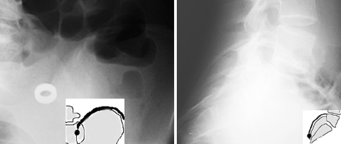
Development of the ossification of the iliac crest is used to assess the remaining spinal growth. The clinical value of the Risser sign has been questioned because of its inaccuracy in grades 3 and 4. Estimation of the Risser sign based on the lateral spinal radiograph has not been reported. The aim of the study was to evaluate the course of ossification of the iliac apophysis along its full extension and to investigate relevance of the lateral spinal radiograph for more accurate Risser sign grading. Cross sectional analysis of spinal frontal and lateral long cassette standing spinal radiographs of 201 girls aged from 10.2 to 20.0 years were done. On the lateral spinal view, the ossification of the posterior part of the iliac apophysis was quantified at four grades: absent (A), partial (B), complete (C) or fused (D). The position of the posterior superior iliac spine was studied on both views as well as in pelvic specimens. The results showed that the posterior one-third portion of the iliac apophysis was sagittally oriented and obscured on the frontal radiograph by the sacroiliac junction. It could be studied on the lateral radiograph and revealed a different grading of the apophysis excursion in 58 of 201 (29%) patients, comparing to the frontal view. Both advanced or delayed ossification was observed and assessed with Lateral Risser Modifiers. Twenty-five percent of the patients at Risser 0 or 1 or 2 demonstrated a simultaneous ossification of the most anterior and the most posterior part of the iliac crest. The Risser grades of capping or fusion could be more precisely diagnosed using lateral radiograph in complement to the frontal one. The conclusions drawn from this study were: (1) Currently used Risser sign grading does not consider the actual excursion of the iliac apophysis, because one-third of the apophysis cannot be observed on the frontal radiograph. (2) Iliac apophysis full excursion or fusion can be more accurately estimated when the lateral spinal radiograph is analyzed with Lateral Risser Modifiers.
Electronic supplementary material
The online version of this article (doi:10.1007/s00586-008-0794-7) contains supplementary material, which is available to authorized users.
Keywords: Idiopathic scoliosis, Risser sign, Iliac apophysis, Bone age
Introduction
The dangerous rapid progression of idiopathic scoliosis occurs during the period of the rapid spinal growth [2, 9]. Estimation of the residual spinal growth for any given patient is based on clinical data, including the chronological age, height gain, and date of menarche [8]. Radiological parameters, such as wrist bone age [4], vertebral apophysis ring test [10], elbow bone age, triradiate acetabular cartilage closure, femoral head cartilage closure, rib epiphysis appearance [5], proximal humeral cartilage closure and the Risser sign [12] are considered.
The Risser sign was criticized for limited accuracy in predicting residual spinal growth. Nevertheless, the Risser sign remains “an invaluable sign in the management of scoliosis” [12] because it is relatively simple in use. Moreover, it enables to quantify apophysis excursion, providing numeric data. This can be used for further analysis, for example, for calculation of the progression factor of Lonstein and Carlson [9]. Improving the accuracy of Risser sign grading would substantially improve the usefulness of the Risser sign [5, 8, 13].
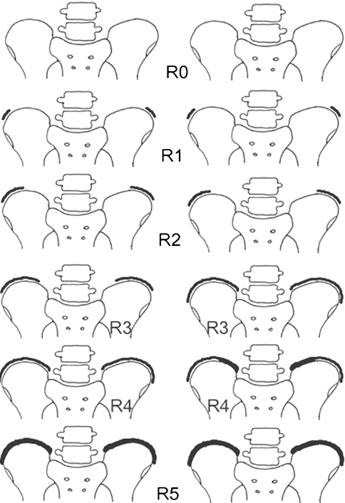
Maturation of the iliac bone manifests on the frontal postero-anterior (PA) or antero-posterior (AP) spinal radiographs, as a progressive ossification of the iliac bone apophysis, beginning at the anterior superior iliac spine (ASIS) and extending backward to the posterior superior iliac spine (PSIS). Joseph Risser [12] described six grades from Risser 0 (no apophysis visible) through Risser 5 (fusion of the apophysis to the ilium). Risser 1 is 25% excursion, Risser 2 50% excursion, Risser 3 75% and Risser 4 is complete excursion. Differences in Risser sign grading have been reported in France [1], namely, for the grade 3 and the grade 4, Fig. 1.
Fig. 1.
Risser sign grading system presented in its original form (left column) and in the so called French modification (right column). Differences concern grade 3 and grade 4
Good visualization of the excursion of the iliac apophysis up to the posterior superior iliac spine is critical for correct Risser sign grading. Unfortunately, the PSIS is seen neither on AP nor PA radiographs, because it is hidden behind the sacroiliac junction. Izumi [6] placed metal markers on the iliac crest of a pelvis specimen and reported superimposition over the ilium. Moreover, Risser sign grading assessed on the PA radiograph may differ from that on AP view, due to the spatial orientation of the iliac crest: the radiolucent cartilaginous “gap” is best seen when tangential to the direction of the X-ray beam. The worst concordance between the AP and the PA radiograph, averaging 19% only, was reported for Risser grade 3 [6]. Shuren et al. [13] used bending films to reevaluate the Risser sign and did not find significant difference from the results obtained on the PA films. However, they reported difficulties in differentiation between Risser 4 and Risser 5 on PA films due to the superposition of the iliac bone and the iliac apophysis. A review of the literature on Risser sign grading revealed more controversies on accurate determination of grade R3, R4 and R5, while the initial stages of the absence (Risser 0) or first appearance (Risser 1 and Risser 2) of the iliac apophysis seem to raise less doubts.
An observation was made by the author that the Risser 3, 4 and 5 grades can be assessed on the lateral spinal radiograph, which allows the visualization of the full excursion of the iliac apophysis up to the posterior superior iliac spine. The aim of this study was to evaluate concomitantly, the frontal (AP) and the lateral spinal radiographs for iliac apophysis excursion and to assess the usefulness of the lateral radiograph in the more precise estimation of the Risser sign value. The null hypothesis was that there is no difference in the visualization of critical landmarks to assess the iliac apophysis excursion between AP and lateral radiographs.
Materials and methods
Charts of 201 consecutive adolescent girls, seen by the author for surgical or brace treatment for idiopathic scoliosis, were retrospectively reviewed. The patients underwent AP and lateral standing long cassette spinal radiographs. The patients and their parents did agree to undergo two spinal radiographs. The delivered dose for both the frontal and the lateral spinal radiograph has been systematically measured and registered in the patient’s medical documentation. The dose for the lateral spinal radiograph was usually 1.5–2.0 times higher over the dose for the frontal radiograph. In the series of normally built and not obese adolescent girls with idiopathic scoliosis, the delivered dose was of 50 μGy/m2 for the frontal full spine radiograph while it was of 90 μGy/m2 for the lateral full spine radiograph. The mean chronological age was 14.6 ± 2.2 years, range 10.2–20.0. The mean Cobb angle of the main curve was 55.0 ± 22.6°, range 21.0–128.0.
The Risser sign was staged on the AP radiograph, according to the original description of Joseph Risser [12] (Fig. 1, left column). The staging according to the French modification [1] for grades 3 and 4 (Fig. 1, right column) was performed separately. Then on the lateral radiograph, the excursion of the posterior portion of the iliac apophysis was studied. This part of the apophysis was situated posteriorly to the anterior aspect of the vertebral body of L5 and extended downwards to the posterior superior iliac spine (Fig. 2). The ossification of the apophysis was staged with Lateral Risser Modifiers as: absent (A), partial (B) or complete (C). The definite fusion of the iliac apophysis was staged as (D). The intra-observer agreement was checked with three independent measurements. The inter-observer agreement was studied with the assessment made by four independent observers, orthopedic surgeons, on the radiographs of 15 randomly chosen patients. Kendall concordance coefficient and non-parametric ANOVA were used.
Fig. 2.
The posterior part of the iliac crest cannot be seen on the standard frontal spinal radiograph. However, it is clearly outlined on the lateral spinal radiograph. ASIS anterior superior iliac spine. PSIS posterior superior iliac spine. * part of the apophysis visible on the frontal radiograph. + part of the apophysis not visible on the frontal radiograph but visible on the lateral radiograph
The incompatibility found (Tables 1, 2), between the AP Risser sign grading versus the lateral Risser sign grading, raised the hypothesis that there existed discrepancy in the visibility of the posterior portion of the iliac apophysis between the two radiological views. Thus, an analysis was performed to situate the PSIS on each view. The position of the PSIS was related to the spinal level: either to the level of adjacent vertebrae (L5, S1 or S2) or to the level of the intervertebral spaces (L4/L5, L5/S1, S1/S2) (Table 3). The procedure was as follows: on the AP radiograph, the PSIS was outlined as the point immediately superior and lateral to the proximal end of the sacroiliac junction. Such a point was chosen according to the presentation in the figures reproduced in manuals of orthopedics [3, 10, 11, 14] (See Electronic Supplementary Material). On the lateral spinal radiograph, the PSIS could be clearly observed and outlined as the most posterior point of the iliac crest (Fig. 2). The AP level and the lateral level of the PSIS were compared for each patient to demonstrate, whether the PSIS outlined on the AP view and the one outlined on the lateral view corresponded to the same point.
Table 1.
Lateral Risser Modifiers for patients Risser 0 through Risser 2
| Lateral Risser Modifier | Antero-posterior grading | |||||
|---|---|---|---|---|---|---|
| Apophysis excursion | Schematic presentation | Risser 0 0% excursion 
|
Risser 1 25% excursion 
|
Risser 2 50% excursion 
|
All | |
| A | Absent |  |
44a | 12a | 6a | 62 |
| B | Partial |  |
2 | 8 | 11 | 21 |
| C | Complete | 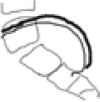 |
0 | 0 | 0 | 0 |
| D | Fused | 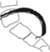 |
0 | 0 | 0 | 0 |
| All patients | 46 | 20 | 17 | 83 | ||
aIndicates perfect agreement between the two radiological views
Table 2.
Lateral Risser Modifier for patients Risser 3 through Risser 5
| Lateral Risser Modifier | Antero-posterior grading | |||||
|---|---|---|---|---|---|---|
| Apophysis excursion | Schematic presentation | Risser 3 75% excursion 
|
Risser 4 100% excursion 
|
Risser 5 fusion 
|
All | |
| A | Absent | 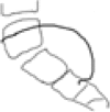 |
1 | 0 | 0 | 1 |
| B | Partial |  |
6a | 5 | 0 | 11 |
| C | Complete | 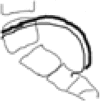 |
14 | 38a | 0 | 52 |
| D | Fused | 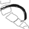 |
0 | 17 | 37a | 54 |
| All patients | 21 | 60 | 37 | 118 | ||
aIndicates perfect agreement between the two radiological views
Table 3.
Position of the posterior superior iliac spine (PSIS) related to the level of the adjacent vertebra
| Level | Vertebral level of PSIS | Number of patients at the level | |
|---|---|---|---|
| AP | LAT | ||
| 1 | L4/L5 | 3 | 0 |
| 2 | L5 | 112 | 3 |
| 3 | L5/S1 | 59 | 4 |
| 4 | S1 | 15 | 96 |
| 5 | S1/S2 | 1 | 52 |
| 6 | S2 | 0 | 35 |
Assessment done on the antero-posterior (AP) and lateral (LAT) spinal radiograph. The L5 is the mode value in the AP group, while the S1 is the mode value in the LAT group. The medians of the AP group (median = 2.0) and the LAT group (median = 4.0) differ significantly (Wilcoxon matched pairs test, P < 0.001). N = 190
Additional analysis was performed by placing metal markers on (1) the skin over the posterior iliac spines in ten girls undergoing routine spinal radiographs and (2) the ASIS and PSIS of two anatomic specimens of young female pelvis, available from the Chair of Anthropology of the University of Poznan. In two specimens, the length and the width of the iliac crests were measured. The point situated on the iliac crest, which was considered to be the posterior iliac spine after the frontal radiological view, was found. The distance form the PSIS to that point was measured.
Results
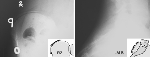
The very posterior part of the iliac crest was clearly observed on the lateral long cassette spinal radiograph in all but four patients (98.0%) who were obese. Forty-four of 46 girls (96%) with the absence of any apophysis shadow on the AP radiograph (Risser 0) presented a concordant lateral stage (Lateral Modifier A), while the remaining two patients (4%) revealed partial ossification at the PSIS (Lateral Modifier B) (Table 1). Twelve of 20 (60%) Risser 1 girls and 6 of 17 (35%) Risser 2 girls revealed a concordant lateral image (Lateral Modifier A). Radiographs of the remaining 19 girls (51%) revealed that the apophysis was partially ossified (Lateral Modifier B). Totally, in 25% of Risser 0 through Risser 2 patients, the ossification of the iliac crest was demonstrated to begin from either the ASIS or the PSIS, Fig. 3.
Fig. 3.
Risser 2B grade. Frontal radiograph (left) demonstrates Risser 2 grade. Lateral radiograph (right) reveals partial ossification of the posterior iliac crest (Lateral Modifier B)
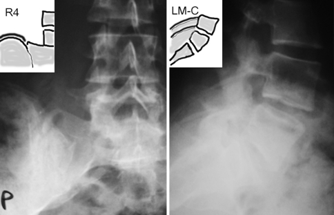
Seven of 21 (33%) Risser 3 girls (75% excursion) revealed concordant lateral image (Lateral Modifier A or B), while 14 (67%) revealed 100% excursion (Lateral Modifier C), Table 2. Five of 60 (8%) Risser 4 girls revealed Lateral Modifier B (Fig. 4), while 38 of 60 (63%) Risser 4 girls revealed Lateral Modifier C (Fig. 5), and 17 (28%) revealed the Lateral Modifier D.
Fig. 4.
Risser 4B grade. Frontal radiograph (left) demonstrates Risser 4 grade. Lateral radiograph (right) reveals only partial ossification of the posterior segment of the iliac crest (Lateral Modifier B). The full excursion has not been achieved yet
Fig. 5.
Risser 4C grade. Frontal radiograph (left) demonstrates Risser 4 grade. Lateral radiograph (right) reveals complete ossification of the posterior iliac crest (Lateral Modifier C). The full excursion has been achieved
All the patients who had the iliac apophysis completely fused on the AP view (Risser 5), presented the same stage (Lateral Modifier D) on the lateral view, Table 2. Among the total of 201 patients, in 58 cases (29%) the analysis of the lateral spinal radiograph provided important information, in addition to the standard radiograph, on the extension of ossification of the iliac apophysis.
The intra-observer agreement was high: 0.96 for the lateral and 0.98 for the frontal view. The inter-observer agreement was substantial for the newly introduced lateral classification, 0.93. It was also very good for the traditional frontal grading of the Risser sign: 0.87.
The position of the PSIS outlined on the frontal radiograph corresponded to the level of L5 vertebra in 112 of 190 cases (59%), Table 3. However, on the lateral radiograph the PSIS was observed to be situated one vertebral level more distally; S1 vertebra in 96 of 190 cases, (50%). The medians revealed in Table 3 of the AP group (median, 2.0) and the LAT group (median, 4.0) were significantly different (Wilcoxon matched pairs test, P < 0.001). In ten girls radiographed with metal markers over each PSIS, there was a perfect concordance between the PSIS level on the frontal and the lateral radiograph; the level of the PSIS corresponded to the level revealed on the lateral spinal radiograph (Table 4).
Table 4.
Position of the posterior superior iliac spine (PSIS) related to the level of the adjacent vertebra, and assessed on the antero-posterior (AP) and lateral (LAT) radiographs in ten girls who were examined having metal markers over the PSISs
| Patient | AP level of PSIS | LAT level of PSIS | AP level concordant with LAT level |
|---|---|---|---|
| K. S. | S1 | S1 | Yes |
| M. M. | S1/S2 | S1/S2 | Yes |
| M. H. | S1 | S1 | Yes |
| K. S. | S1/S2 | S1/S2 | Yes |
| M. G. | S1 | S1 | Yes |
| K. K. | S1 | S1 | Yes |
| P. S. | S1 | S1 | Yes |
| N. L. | S1/S2 | S1/S2 | Yes |
| I. R. | S1 | S1 | Yes |
| K. D. | S1 | S1 | Yes |
The PSIS position corresponds to the level of S1, the same which was observed on the lateral but not on the AP spinal radiographs for the whole sample studied
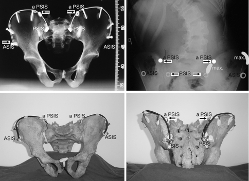
The study of two young female pelvis anatomic specimens located the PSIS at the S1 level. The very posterior portion of the iliac crest could not be seen on the AP radiograph due to its spatial orientation and superposition with the iliac bone (Fig. 6). The width of the iliac crests revealed two maxima: one anterior and one posterior (Table 5). The point commonly considered after the frontal radiograph to be the posterior iliac spine was found to be situated at the junction of the anterior 70% and the posterior 30% of the length of the iliac crest. The mean chronological age of patients Risser 0 through Risser 5 is presented in Table 6.
Fig. 6.
Top left Frontal radiograph of a pelvis specimen with metal markers over the iliac spines. Top right Radiograph of a patient with metal markers over the anterior and posterior iliac spines. The superior dots indicate the points where the iliac apophysis disappears behind the sacrum and behind the iliac bone itself. The inferior dots indicate the posterior superior iliac spines. The maximal thickness of the iliac crest is marked as “max”. These parts of the crest correspond with early appearance of the apophysis ossification. Bottom left Anterior view of the pelvis specimen. Black cable marking the iliac apophysis cannot be seen beyond the aPSIS point. Bottom right Posterior view of the pelvis specimen. The very posterior portion of the iliac crest from the aPSIS up to the PSIS can be observed. ASIS anterior superior iliac spine. PSIS posterior superior iliac spine. aPSIS, apparent PSIS, the point commonly considered to be the PSIS, which is actually situated at the junction of the 70% anterior and the 30% posterior of the total length of the iliac crest
Table 5.
Thickness of the iliac crest (in mm) measured along its length at 1 cm intervals, from the anterior to the posterior superior iliac spine
| Distance from the ASIS along the crest (cm) | Specimen I Iliac crest width |
Specimen II Iliac crest width |
||
|---|---|---|---|---|
| Left | Right | Left | Right | |
| 1 | 12.1 | 11.5 | 11.2 | 12.2 |
| 2 | 10.7 | 10.3 | 11.2 | 11.3 |
| 3 | 7.8 | 10.0 | 9.7 | 10.9 |
| 4 | 8.9 | 9.6 | 9.8 | 9.2 |
| 5 | 10.7 | 14.7 | 11.5 | 11.6 |
| 6 | 13.8 | 16.5 | 13.8 | 14.4 |
| 7 | 17.3 | 14.6 | 14.6 | 14.9 |
| 8 | 15.8 | 12.2 | 12.2 | 11.8 |
| 9 | 10.9 | 9.0 | 9.4 | 10.0 |
| 10 | 7.4 | 7.4 | 8.1 | 9.2 |
| 11 | 6.2 | 6.4 | 9.5 | 10.2 |
| 12 | 5.8 | 6.3 | 10.3 | 10.1 |
| 13 | 6.7 | 7.0 | 10.7 | 10.1 |
| 14 | 6.5 | 6.9 | 11.4 | 11.0 |
| 15 | 7.4 | 8.6 | 12.2 | 11.4 |
| 16 | 9.4 | 10.5 | 13.1 | 12.3 |
| 17 | 10.0 | 8.9 | 15.2 | 16.2 |
| 18 | 10.4 | 11.3 | 16.5 | 17.1 |
| 19 | 11.4 | 12.6 | 17.6 | 17.5 |
| 20 | 11.9 | 14.1 | 15.1 | 15.5 |
| 21 | 14.8 | 16.4 | 8.9 | 7.3 |
| 22 | 15.7 | 12.5 | ||
| 23 | 8.6 | 6.1 | ||
The length of the iliac crest of Specimen I was 23.5 cm, of Specimen II was 21.5 cm. Two maxima, one anterior and one posterior are detected, corresponding to the segments of first appearance of apophysis ossification
Table 6.
Chronological age and Risser sign value
| Risser sign | No. of cases | Chronological age (mean ± SD) | Min–max |
|---|---|---|---|
| 0 | 46 | 12.4 ± 1.2 | 10.2–15.0 |
| 1 | 20 | 13.9 ± 1.5 | 11.2–16.9 |
| 2 | 17 | 13.9 ± 1.1 | 12.2–15.8 |
| 3 | 21 | 14.3 ± 0.9 | 12.3–15.7 |
| 4 | 60 | 15.0 ± 1.2 | 12.2–17.6 |
| 5 | 37 | 17.3 ± 2.0 | 14.0–20.0 |
| all | 201 | 14.6 ± 2.2 | 10.2–20.0 |
Risser 0 and Risser 5 groups differ significantly from any other group (Kruskal–Wallis test, nonparametric ANOVA), differences among Risser 1, Risser 2, Risser 3 or Risser 4 were not significant (Dunn’s multiple comparison test).
SD standard deviation
The so called French modification [1] of the Risser sign grading, concerning grade 3 and 4, was studied in Table 7. The Risser 4 group revealed heterogeneity in the degree of ossification of the iliac apophysis. On the standard AP radiograph, the partial fusion of the apophysis at its part closest to the sacroiliac junction was observed in 36 of 60 (60%) Risser 4 patients. This finding apparently supported the idea of the Risser 4 “French” to be a particular stage of ossification of the iliac apophysis. However, as much as 22 of 36 (61%) patients, defined as Risser 4 “French” grade, revealed complete excursion but not fusion on the lateral radiograph (Lateral Modifier C), Fig. 7.
Table 7.
Subdivision of 60 Risser 4 girls, according to the degree of ossification of the iliac apophysis: non fused or fused at the posterior superior iliac spine
| Risser grade 4 | Antero-posterior radiograph | All patients | ||
|---|---|---|---|---|
| Complete excursion but no fusion | Fusion around the PSIS (“French” type) | |||
| Lateral radiograph | ||||
| Lat. B or Lat. C Modifier: no fusion around the PSIS |
21a | 22 | 43 | |
| Lat. D Modifier: fusion around the PSIS |
3 | 14a | 17 | |
| All patients | 24 | 36 | 60 | |
aIndicates perfect agreement between the two radiological views
Fig. 7.
The example of a false case of the so called “French” Risser 4 grade. Frontal radiograph reveals partial fusion of the iliac crest. However, the lateral radiograph proves that there is no fusion of the posterior apophysis (Lateral Modifier C)
Discussion
Visibility of the PSIS on standard spinal radiographs
The position of the PSIS outlined on the standard AP spinal radiograph for a given patient did not correspond to the same point on the lateral radiograph (P < 0.001). The former revealed the L5 level, the latter the S1 level. However, both radiological views showed the S1 level, when metal markers were placed over the PSIS. Therefore, the lateral radiograph was found to be reliable for defining the location of the posterior iliac spine.
In the figures reproduced in the manuals of orthopedics [3, 10, 11, 14], the point of full posterior excursion of the iliac apophysis is indicated to be situated just lateral and superior to the sacroiliac junction as presented in Fig. 1. Actually, such a point is situated at the junction of the anterior 70% and the posterior 30% of the length of the iliac crest (Fig. 6). Thus, the assessment of the iliac apophysis excursion made exclusively on the frontal spinal radiograph misses 30% of the excursion. On the standard lateral long cassette standing spinal radiograph the posterior portion of apophysis is seen clearly, and the ossification can be assessed with Lateral Risser Modifiers A through D.
The study of the pelvic bony specimens revealed the sagittal orientation of the posterior part of the iliac bone, as well as strongly oblique inferior and posterior course of the iliac crest (Supplementary Fig. 1). This is why, this part of the iliac apophysis is obscured by the sacral bone and the iliac bone itself on the standard AP or PA spinal radiographs. The sagittal orientation of this part of the iliac crest, which is situated behind the sacroiliac junction, makes it favorably positioned for lateral radiography (perpendicular to the direction of the X-ray beam). In fact, the lateral spinal radiograph revealed the whole posterior part of the iliac apophysis up to the posterior iliac spine.
The iliac apophysis was not well seen in obese patients. The use of bright light lamp was helpful. The iliac apophysis can be first detected in its most upper part, posterior to the vertebral body of L4, then the course of the apophysis can be followed backwards and down to the S1 level.
Contribution of the lateral spinal radiograph
Two of 46 (4%) Risser 0 girls, 8 of 20 (40%) Risser 1 girls, as well as 11 of 17 (65%) Risser 2 girls revealed lateral modifier B, signifying partial ossification of the posterior part of the apophysis, Table 1. These findings suggest that in a number of patients the iliac apophysis ossifies from both anterior and posterior end. The iliac crest develops its maximum thickness twice: in the most anterior and in the most posterior part (Table 5). This fact is known from surgical practice, as these parts of the ilium are preferable sources of bone graft. It seems logical that the appearance of a secondary ossification center depends on the local volume of cartilage and underlying bone. The two maxima of the width of the iliac crest noted in the anatomic specimens corresponded to those parts of the iliac crest where the iliac apophysis shadow appeared first. Lateral Risser Modifiers enabled early observation of posterior apophysis ossification, not detectable on the standard frontal radiograph.
The study confirmed the existence of the frontal plane images described as the French modification for the Risser 4 grade, consisting of the image of partial fusion of the apophysis in its part closest to the sacroiliac junction (Fig. 1, right column). However, this study questions, whether such an image signifies a real separate stage of ossification, because the lateral radiograph confirmed the fusion only in 14 of 36 cases (39%), Table 7. This study showed that sagittal and caudad orientation of the posterior portion of the iliac crest could be responsible for creating a false image of apophysis fusion (“French” Risser 4) in 22 of 36 (61%) patients. Increased thickness of the ossifying apophysis and decreased width of the cartilaginous lucent “gap” were accompanying factors to create a false image of fusion. Fortunately, on the lateral radiograph the posterior part of the iliac crest is oriented parallel to the cassette, so the apophysis can be precisely observed. The above described stage of ossification can be named Risser 4D.
Clinical relevance
The predictive value of the Risser sign for spinal growth cessation was questioned by several authors [7, 8] because residual growth after full iliac apophysis excursion (Risser 4) was reported. Little and Sussman [7] concluded that the Risser sign is not sufficiently accurate to substitute for a hand–wrist radiograph as a measure of skeletal maturity in an individual patient. Hoppenfeld et al. [5] concluded that the complete excursion of the iliac crest (Risser 4) is not the final indicator for the end of spinal growth. Little et al. [8] found 9 of 88 patients (10%) to have the maximum of curve progression after the Risser sign had reached the grade 4. This study demonstrated that 5 of 60 Risser 4 patients (8%) did not reveal the Lateral Modifier C (complete excursion) but the Lateral Modifier B only, so they could present residual spinal growth.
Using the standard lateral spinal radiograph is simple and does not expose the patient to additional irradiation. Therefore, it can be proposed to facilitate making therapeutic decision, based on an increased accuracy of the assessment of the Risser sign for predicting the spinal growth potential.
Conclusions
Currently used Risser sign grading does not consider the complete excursion of the iliac apophysis, because the apophysis posterior and medial to the sacroiliac junction cannot be observed on a frontal spinal radiograph.
Iliac apophysis excursion and fusion can be accurately estimated when the lateral spinal radiograph is analyzed and Lateral Risser Modifiers A through D are considered.
Electronic supplementary material
Below is the link to the electronic supplementary material.
Fig. 1 PSIS on the top view (left) and lateral view (right) of the pelvis specimen. The position of the posterior superior iliac spine is marked as PSIS while the position apparently taken for the PSIS on standard frontal radiograph is marked as aPSIS. In this case the distance from PSIS to aPSIS covers 28% of the total length of the iliac crest. This part can be seen on the lateral radiograph exclusively (TIFF 1413 kb)
Fig. 2 White arrow indicates the apparent location of the PSIS reproduced in figures in orthopedic manuals. Red-and-white arrow indicates the actual location of the PSIS. Red line indicates the portion of the iliac apophysis which can be studied on the standard AP or PA radiograph. Green line indicates the portion of the iliac apophysis which cannot be studied on standard AP or PA radiographs but can be seen on lateral radiograph (TIFF 680 kb)
Fig. 3 Risser sign staging according to A.A. DeSmet: Radiology of spinal curvatures. Mosby 1985: page 45(TIFF 203 kb)
Fig. 4 Risser sign staging according to M. Tachdjian: Pediatric Orthopedics. Saunders 1990, page 2290 (TIFF 319 kb)
Fig. 5 Risser sign staging according to A.G. Martinez-Lozano: Embriology, Growth and Maturation [in:] Weinstein (ed.) The Pediatric Spine. Principles and Practice. Raven Press 1994, page 1864 (TIFF 390 kb)
Fig. 6 D CT reconstruction of the pelvis exposed in Boston Museum of Science. aPSIS indicates the point taken for posterior iliac spine on the frontal radiograph. PSIS indicates the actual posterior superior iliac spine. max. indicates posterior maximum of the thickness of the iliac crest (TIFF 1175 kb)
Fig. 7 CT scan passing through the anterior and posterior iliac spines demonstrates non-fused iliac apophysis. The PSIS is situated at the level of S1 vertebra (TIFF 657 kb)
Acknowledgments
To Prof. J. Piontek for availability of pelvic specimens. To Dr. M. Walczak, Dr. M. Idzior and Dr. M. Tomaszewski for participation in the inter-observer study. To Prof. M. Hawes and Mr. J. O’Brien for substantial and language assistance.
References
- 1.Bitan FD, Veliskakis KP, Campbell BC. Differences in the Risser grading systems in the United States and France. Clin Orthop Relat Res. 2005;436:190–195. doi: 10.1097/01.blo.0000160819.10767.88. [DOI] [PubMed] [Google Scholar]
- 2.Bunnell WP. The natural history of idiopathic scoliosis before skeletal maturity. Spine. 1986;11:773–776. doi: 10.1097/00007632-198610000-00003. [DOI] [PubMed] [Google Scholar]
- 3.DeSmet AA (1985) Radiology of spinal curvatures. Mosby p 45
- 4.Greulich W, Pyle SI. Radiographic atlas of skeletal development of the hand and wrist. Stanford: Stanford University Press; 1959. [Google Scholar]
- 5.Hoppenfeld S, Lonner B, Murthy V, Gu Y. The rib epiphysis and other growth centers as indicators of the end of spinal growth. Spine. 2003;29:47–50. doi: 10.1097/01.BRS.0000103941.50129.66. [DOI] [PubMed] [Google Scholar]
- 6.Izumi Y. The accuracy of Risser staging. Spine. 1995;20:1868–1871. doi: 10.1097/00007632-199509000-00004. [DOI] [PubMed] [Google Scholar]
- 7.Little DG, Sussman M. The Risser sign: a critical analysis. J Pediatr Orthop. 1994;14:569–575. doi: 10.1097/01241398-199409000-00003. [DOI] [PubMed] [Google Scholar]
- 8.Little DG, Song KM, Katz D, Herring JA. Relationship of peak height velocity to other maturity indicators in idiopathic scoliosis in girls. J Bone Joint Surg. 2000;82A:685–693. doi: 10.2106/00004623-200005000-00009. [DOI] [PubMed] [Google Scholar]
- 9.Lonstein JE, Carlson JM. The prediction of curve progression in untreated idiopathic scoliosis during growth. J Bone Joint Surg Am. 1984;66:1061–1071. [PubMed] [Google Scholar]
- 10.Martinez-Lozano AG (1994) Embryology, growth and maturation. In: Weinstein SL (ed) The pediatric spine. Principles and practice. Raven Press, p 1864
- 11.Moe JH, Winter RB, Bradford DS, Lonstein JE. Scoliosis and other spinal deformities. Philadelphia: Saunders; 1978. p. 35. [Google Scholar]
- 12.Risser JC. The iliac apophysis. An invaluable sign in the management of scoliosis. Clin Orthop Relat Res. 1958;11:111–119. [PubMed] [Google Scholar]
- 13.Shuren N, Kasser JR, Emans J, et al. Reevaluation of the use of the Risser sign in idiopathic scoliosis. Spine. 1982;17:359–361. doi: 10.1097/00007632-199203000-00020. [DOI] [PubMed] [Google Scholar]
- 14.Tachdjian M. Pediatric Orthopedics. Philadelphia: Saunders; 1990. p. 2290. [Google Scholar]
Associated Data
This section collects any data citations, data availability statements, or supplementary materials included in this article.
Supplementary Materials
Below is the link to the electronic supplementary material.
Fig. 1 PSIS on the top view (left) and lateral view (right) of the pelvis specimen. The position of the posterior superior iliac spine is marked as PSIS while the position apparently taken for the PSIS on standard frontal radiograph is marked as aPSIS. In this case the distance from PSIS to aPSIS covers 28% of the total length of the iliac crest. This part can be seen on the lateral radiograph exclusively (TIFF 1413 kb)
Fig. 2 White arrow indicates the apparent location of the PSIS reproduced in figures in orthopedic manuals. Red-and-white arrow indicates the actual location of the PSIS. Red line indicates the portion of the iliac apophysis which can be studied on the standard AP or PA radiograph. Green line indicates the portion of the iliac apophysis which cannot be studied on standard AP or PA radiographs but can be seen on lateral radiograph (TIFF 680 kb)
Fig. 3 Risser sign staging according to A.A. DeSmet: Radiology of spinal curvatures. Mosby 1985: page 45(TIFF 203 kb)
Fig. 4 Risser sign staging according to M. Tachdjian: Pediatric Orthopedics. Saunders 1990, page 2290 (TIFF 319 kb)
Fig. 5 Risser sign staging according to A.G. Martinez-Lozano: Embriology, Growth and Maturation [in:] Weinstein (ed.) The Pediatric Spine. Principles and Practice. Raven Press 1994, page 1864 (TIFF 390 kb)
Fig. 6 D CT reconstruction of the pelvis exposed in Boston Museum of Science. aPSIS indicates the point taken for posterior iliac spine on the frontal radiograph. PSIS indicates the actual posterior superior iliac spine. max. indicates posterior maximum of the thickness of the iliac crest (TIFF 1175 kb)
Fig. 7 CT scan passing through the anterior and posterior iliac spines demonstrates non-fused iliac apophysis. The PSIS is situated at the level of S1 vertebra (TIFF 657 kb)


