Abstract
Segmental instability in degenerative disc disease is often treated with anterior lumbar interbody fusion (ALIF). Current techniques require an additional posterior approach to achieve sufficient stability. The test device is an implant which consists of a PEEK-body and an integrated anterior titanium plate hosting four diverging locking screws. The test device avoids posterior fixation by enhancing stability via the locking screws. The test device was compared to an already established stand alone interbody implant in a human cadaveric three-dimensional stiffness test. In the biomechanical test, the L4/5 motion segment of 16 human cadaveric lumbar spines were isolated and divided into two test groups. Tests were performed in flexion, extension, right and left lateral bending, right and left axial rotation. Each specimen was tested in native state first, then a discectomy was performed and either of the test implants was applied. Finite element analysis (FE) was also performed to investigate load and stress distribution within the implant in several loading conditions. The FE models simulated two load cases. These were flexion and extension with a moment of 5 Nm. The biomechanical testing revealed a greater stiffness in lateral bending for the SynFix-LR™ compared to the established implant. Both implants showed a significantly higher stiffness in all loading directions compared to the native segment. In flexion loading, the PEEK component takes on most of the load, whereas the majority of the extension load is put on the screws and the screw–plate junction. Clinical investigation of the test device seems reasonable based on the good results reported here.
Keywords: Biomechanics, Lumbar spine, Finite element analysis, Interbody fusion
Introduction
Lumbar interbody fusion can be performed using a posterior, anterior or combined approach. In recent years, anterior lumbar interbody fusion (ALIF), in association with a variety of methods to stabilize both the implant and motion segment, has increased in popularity. The reason behind this was an attempt to achieve symptomatic relief, whilst avoiding the morbidity associated with posterior lumbar fusion.
Previously, additional fixation with posterior instrumentation has been required in order to maintain sufficient stability to reliably achieve a bony fusion. However, additional fixation requires more extensive surgery and increases morbidity.
The use of a lumbar interbody fusion device with additional posterior fixation was shown to significantly improve fusion rate, but did not lead to a higher clinical success rate [9].
These drawbacks may be overcome through the use of a device that can be inserted with minimal operative morbidity, and without causing damage to neural, vascular and muscle tissues. The challenge is to provide sufficient stability to reliably achieve fusion without increasing the morbidity of the approach.
The SynFix-LR™ is a new stand alone ALIF device which satisfies the biomechanical requirements for a stand alone interbody fusion device [4].
The objectives of the research reported in this paper were twofold. The first being to compare the three-dimensional stability of the stand alone ALIF SynFix-LR™ with that of the already introduced STALIF™. This was done by biomechanical testing in a human cadaveric model. The second objective was to demonstrate the proportions of the load which are borne by the cage, stabilization plate and screws. The distribution of load and stress on the SynFix-LR™ was investigated under several loading conditions using finite element (FE) models.
Methods
Biomechanical testing
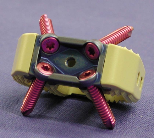
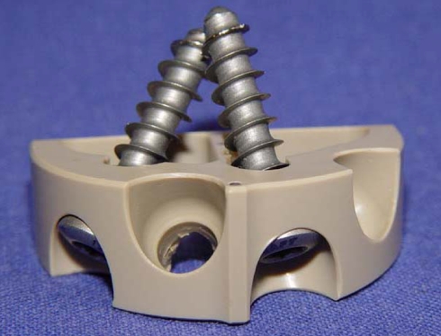
Two implants were compared in biomechanical testing, namely, the SynFix-LR™ (Synthes GmbH, Oberdorf, Switzerland; Fig. 1) and the STALIF™ (Surgicraft Ltd., Redditch, UK; Fig. 2).
Fig. 1.
SynFix; anterocaudal view with locking screws inserted
Fig. 2.
STALIF; anterior view with two of four possible screws inserted
The SynFix-LR™ incorporates an anterior stabilization plate as an integrated element with a reduced anterior profile (Fig. 1). The cage, stabilization plate and fixation screws are all contained within the intervertebral space which prevents potential irritation or impingement upon adjacent visceral structures and vessels. The plate is designed as a locked internal fixator with divergent screws which is expected to provide sufficient stability via a less invasive approach.
The body of the cage is manufactured from Poly-Ether–Ether-Ketone (PEEK) and is thus radiolucent to facilitate radiographic evaluation of fusion success. The body of the cage has an anatomically shaped design with a three-dimensional convex superior and inferior surface to optimise load distribution on the endplates. The integrated anterior stabilization plate and its fixed and divergent locking screws are constructed from titanium alloy. The plate lies entirely within the disc space reducing the risk of damage to adjacent major vessels and nerves. The insertion of an adequate volume of cancellous bone graft or bone substitute material is possible due to the configuration of the components.
The STALIF™ is also proposed as a stand alone anterior fusion device with additional stabilization achieved by screws. These screws fix the cage to the vertebral body, but are not fixed in their angle. In the cranio–caudal view, the anterior rim is semicircular to reduce subsidence due to placement on the apophyseal ring of the vertebral body. In the lateral view, the anterior rim is higher than the posterior, so the wedge-like shape helps restore lumbar spine lordosis. The interbody device was also made of PEEK. The implant is fixed with 3–4 non-angle stable screws, which are directed alternatingly through holes in the anterior rim of the cage to the centre of the adjacent vertebral bodies. The STALIF screws are also larger with a cancellous thread (Fig. 2).
The indications and contraindications for the use of both implants are identical and include localised symptomatic degenerative disc disease, revision surgery for failed decompression syndrome and pseudoarthrosis. Contraindications include spinal fractures, spinal tumour, osteoporosis, infection, spondylolisthesis and severe segmental instability.
Biomechanical testing was performed on 16 human lumbar spine specimens. The average age of the donors, including eight females and eight males, was 49.6 ± 8.6 years (range 35–65). The medical history of each donor was reviewed to exclude trauma, malignancy or metabolic pathologies of the spine. Each specimen was radiographically screened to exclude osteolysis, fractures or other abnormalities, including abnormal bone mineral density. In addition, quantitative computerised tomography was performed using a Siemens Somatom plus 4 scanner (Siemens Inc., Erlangen, Germany) to determine bone mineral density (BMD) of L4 and L5; the BMD for all specimens were within the normal range for age matched controls.
The specimens were frozen directly after harvesting and stored at −20°C. They were thawed in a 25°C water bath immediately before preparation and testing. After thawing, paravertebral musculature and connective tissue were removed, with care taken to preserve the ligamentous structures and facet joint capsules.
The L4/5 motion segments were then isolated. The distal ends of the specimens were embedded in poly-methyl-methacrylate (PMMA; Technovit 3040; Heraeus Kulzer GmbH, Wehrheim/Ts, Germany), using fixation pods.
Test setup and study protocol
Specimens were randomly assigned to one of two implants, stratified for age and gender. All segments were tested in a native state before performing an anterior discectomy in which all but the posterior annulus was removed. This provided a test environment where the stability of the segment was principally determined by the implant rather than the annulus. Instrumentation of either a SynFix or STALIF implant of an appropriate size was then undertaken according to the manufacturer’s recommendations. An aiming device was used for setting the drill holes and the locking screws in the SynFix implant in order to ensure appropriate alignment of the locking screws to the anterior plate.
The motion segments were tested with a non-destructive three-dimensional stiffness method based on the test setup of Crawford et al. [6]. A system of cable wires and pulleys was used to induce flexion, extension, left and right bending and left and right rotation. Since the upper part of the specimen is fixed only by the cables, it is able to float in a relatively unconstrained manner. An axial preload consisted of the weight load of the upper fixation pod, which added up to 0.985 kg. One can assume an axial preload of about 10 N, though. The test setup was mounted on a material testing machine (Zwick 1456, Zwick GmbH, Ulm). Applied forces were measured with an axial load cell (Z12, HBM, Darmstadt) integrated in the test setup.
Pure bending moments were calculated by multiplying the applied force by the radius of the pulley. The specimens were loaded and unloaded four times with a maximum load of 6 Nm to minimise viscoelastic influence. The speed of the uniaxial testing machine was 100 mm/min, which resulted in a calculated angular displacement of approximately 1.08°/s. The fourth cycle was used for evaluation. Extension, flexion, bending (right, left) and rotation (right, left) were tested.
The three-dimensional movement of each motion segment was measured using a passive infrared optical motion tracking system (Qualysis Inc., Sävebalden, Sweden). Three reflecting markers were mounted on the upper and lower vertebral body. The angular displacement of L4 compared to L5 was calculated using custom made software. The error associated with this method was estimated to be ±0.12° [10].
The angular displacement under zero load at the beginning of the test, under zero load after the third cycle, and under maximal load during the fourth cycle, were used to calculate the range of motion (ROM) and neutral zone (NZ) of the tested motion.
Statistical analysis
Statistical analyses were performed using rmANOVA for absolute values of ROM and NZ and univariate ANOVA for comparing relative values of the two implants. Significance was assumed for P < 0.05.
Finite element models
Finite element (FE) models provide an additional facet to a better understanding of the human lumbar spine. These models are used to show the distribution of load and stress on implants and their components, and the supporting bony elements. The simulation examined the primary stability of the SynFix-LR™ implant.
In this paper, the SynFix-LR™ was modelled under different loading conditions. The components of the SynFix-LR™ are produced from different materials. The cage is made from PEEK whereas the stabilization plate and screws are made from titanium. Therefore, it was important to choose meshing elements that best describe the deformation of each material and appropriate elements were selected for the PEEK cage, stabilization plate and screws.
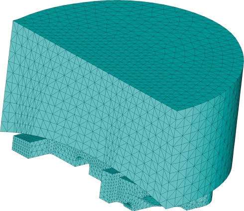
The modelling of the vertebral bodies was performed according to Wong [18]. The vertebral body of the FEA model consisted of a solid tetrahedral core of trabecular bone surrounded by a cortical shell.
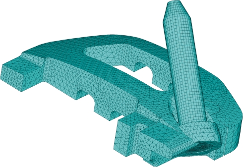
The model representing the implant is symmetric in two planes, and it was therefore acceptable to use ¼ of the model for calculations in the three-dimensional FE-Model (Figs. 3, 4). This reduces the time for calculation.
Fig. 3.
The meshed model of vertebra for analysis of pure axial compression and tension contains 224,183 elements
Fig. 4.
The meshed model of cage, plate and screw for analysis of pure axial compression and tension contains 321,586 elements
The PEEK cage was modelled from a volumetric mesh of tetrahedral elements each having ten nodes (four corners and six midside nodes).
The stabilization plate was modelled from a volumetric mesh of hexahedral elements each having 20 nodes (eight corners and 12 midside nodes).
The screws were modelled from a volumetric mesh of hexahedral elements each having eight nodes (eight corners, without midside nodes). Because the mesh of the screws was made from a regular mesh with a small element size, midside nodes were not necessary. It was assumed that the fixation screws are firmly attached to the vertebra, and that the vertebra has intimate contact with, but remained separate from the cage. It was also assumed that there is no direct contact between the vertebra and the stabilization plate. The two load cases that were analysed were extension and flexion.
For the analysis of extension and flexion, superimposed loads (moments of 5 Nm) were applied with axial preload of 600 N.
Results
Biomechanical testing
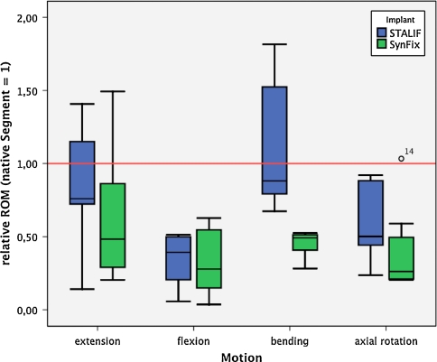
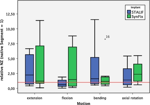
Biomechanical testing was used to compare the three-dimensional stability of the SynFix-LR™ with the STALIF device. The results are depicted in Tables 1, 2, 3, 4; Figs. 5 and 6.
Table 1.
Results of biomechanical testing in extension
| Group | Native segment | Instrumented segment | ||
|---|---|---|---|---|
| Mean | SD | Mean | SD | |
| STALIF | 1.49° | 0.90° | 1.26° | 0.85° |
| SynFix | 1.72° | 0.77° | 0.84° | 0.42° |
| STALIF + SynFix | 1.60° | 0.82° | 1.05° | 0.68° |
Values are given as mean ROM (degrees) and standard deviation
Table 2.
Results of biomechanical testing in flexion
| Group | Native segment | Instrumented segment | ||
|---|---|---|---|---|
| Mean | SD | Mean | SD | |
| STALIF | 4.02° | 1.76° | 1.45° | 1.20° |
| SynFix | 3.14° | 1.09° | 0.85° | 0.42° |
| STALIF + SynFix | 3.58° | 1.49° | 1.15° | 0.92° |
Values are given as mean ROM (degrees) and standard deviation
Table 3.
Results of biomechanical testing in lateral bending
| Group | Native segment | Instrumented segment | ||
|---|---|---|---|---|
| Mean | SD | Mean | SD | |
| STALIF | 2.37° | 0.78° | 2.41° | 1.25° |
| SynFix | 2.91° | 1.10° | 1.29° | 0.68° |
| STALIF + SynFix | 2.64° | 0.98° | 1.85° | 1.14° |
Values are given as mean ROM (degrees) and standard deviation
Table 4.
Results of biomechanical testing in axial rotation
| Group | Native segment | Instrumented segment | ||
|---|---|---|---|---|
| Mean | SD | Mean | SD | |
| STALIF | 2.33° | 0.58° | 1.40° | 0.78° |
| SynFix | 2.11° | 0.88° | 0.65° | 0.20° |
| STALIF + SynFix | 2.22° | 0.74° | 1.03° | 0.68° |
Values are given as mean ROM (degrees) and standard deviation
Fig. 5.
Relative results of range of motion (ROM) measurements. Native segment is set as 1 (red line). The black bar indicates the median value, the edges of the box indicate first and third percentile, respectively. Error bars indicate maximum/minimum values. Outliers are defined as a data point extending greater than 1.5 box-lengths from the edge of a boxplot, extremes are defined as data points which extend greater than three box lengths from the edge of a boxplot. Significant differences between groups are indicated
Fig. 6.
Relative results of neutral zone (NZ) measurements. Native segment is set as 1
Extension
In extension, the range of motion (ROM, P = 0.021) was significantly lower in the instrumented segments than in the native segment. Although the difference between instrumented and native segment is much higher in the SynFix than in the STALIF group, no significant differences was found between the implants (P = 0.146).
The neutral zone (NZ) of the instrumented segments was higher than the native segment in both groups, with no significant differences between instrumented and native segment (P = 0.061) or SynFix and STALIF group (P = 0.856).
When comparing the relative values of the parameters in extension (native segment set as 1), the SynFix implant decreased ROM (P = 0.264), whilst achieving nearly equal NZ (P = 0.973) values.
Flexion
In flexion, both implants were able to reduce ROM (P < 0.001) significantly. The influence of the implant used was not significant (ROM, P = 0.663). No significant differences was detected in the NZ between instrumented and native segment (P = 0.844) or between SynFix and STALIF group (P = 0.186).
The relative values of SynFix and STALIF showed a nearly equal ROM (P = 0.853). The NZ was higher in the SynFix group (P = 0.231).
Lateral bending
Assuming the bilateral bending motions are symmetrical, left and right bending was summated as lateral bending.
In lateral bending, the instrumented segments showed a significantly lower ROM (P < 0.001) than the native segment. A strong influence of the implant used was evident (P < 0.001), with lower ROM with SynFix.
The NZ was increased in the STALIF group and nearly equal to the native segment in the SynFix group. Statistical evaluation could not detect significance for the use of instrumentation (P = 0.073) or between the two implant groups (P = 0.356).
The relative ROM of the SynFix implant compared to STALIF were highly significant (P = 0.001). In NZ, a significant difference was not found (P = 0.432).
Axial rotation
Similar to the assumed symmetrical behaviour of lateral bending, left and right rotation values are summated as axial rotation.
Axial rotation measurements showed significantly lower ROM (P < 0.001), with nearly equal NZ (P = 0.108) for instrumented segments. A significant influence of the type of implant was not detectable (ROM, P = 0.082; NZ, P = 0.205).
Relative values showed a similar situation. The reduction of ROM (P = 0.097was more evident in the SynFix group. NZ values were slightly higher for the SynFix group, but not significantly different (P = 0.518).
Finite element models
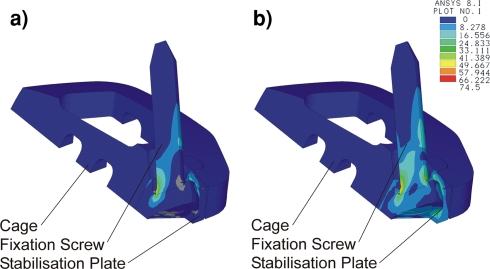
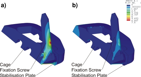
These FE models were used to analyse the distribution of load and stress on the SynFix-LR™. The results of the analyses are summarised in Tables 5 and 1. The stress distributions are shown in Figs. 7 and 8. Blue areas indicate low stress values and red areas indicate maximal stress values. Isolines show the distribution of maximal tensile stress.
Table 5.
Applied moments and results of the FE analysis
| Load case | Mtot (Nm) | FZ at the cage (N) | FZ at the Insert-Plate (N) |
|---|---|---|---|
| Flexion | 5 | 239.8 | 17.1 |
| Extension | 5 | 0 | 78.5 |
Fig. 7.
Oblique reconstruction showing (a) maximal tensile stress and (b) von-Mises comparison stress distribution of the cage, stabilization plate and fixation screw when tested with a flexion load of 5 Nm
Fig. 8.
Oblique reconstruction showing (a) maximal tensile stress and (b) von-Mises comparison stress distribution of the cage, stabilization plate and fixation screw when tested with an extension load of 5 Nm
The cage takes most of the force when loaded in flexion (Table 1). During flexion, the stabilization plate and screws take relatively little force, but are subjected to greater stress than the cage (Fig. 7).
When loaded in extension, the cage takes none of the force applied (Table 1; Fig. 8). Most of the stress is taken by the screws and their junction with the stabilization plate.
Discussion
The management of painful degenerative conditions affecting the lumbar spine represents a major challenge to the spinal surgeon. It is well known that spinal fusion surgery is an effective treatment in the management of this condition [8, 9, 17]. Nevertheless, recent studies indicate a rationale for conservative treatment as well, if a modern rehabilitation programme will be followed [3, 11].
Interbody techniques for spinal fusion play an important role, because they tend to achieve a higher fusion rate than the posterolateral fusion technique [17].
However, it is still a challenge to identify techniques that reliably achieve a stable fusion without being associated with significant postoperative morbidity or other potential complications.
From the biomechanical point of view, the amount of immediate postoperative stabilization, which is necessary for spinal fusion remains unclear. Nevertheless, it seems to be consensus, that an adequate stabilization must greatly increase stiffness above the native status. Good rotational stability is also necessary.
Previous biomechanical studies have demonstrated that stand alone implantation of interbody cage implants shows a good stabilization in flexion and lateral bending, but stabilization in extension and rotation is poor [14].
A potential solution to this clinical dilemma may be the development of an anterior lumbar interbody fusion (ALIF) device with integrated anterior fixation that provides sufficient stability to reliably achieve a fusion, and which can be safely used as a stand alone implant. Anterior fixation devices were previously investigated with this aim in mind.
Le Huec et al. [13], for example, tested an anterolateral threaded intervertebral fusion cage, which was designed to be connected to an anterolateral plate. They could find a significant increase of stiffness in all loading directions with an additive plate. Whether or not the plate was connected to the cage did not play a significant role.
The relation between stand alone threaded cage, additional anterolateral plate, lateral plate and posterior transpedicular fixation method was investigated by Bozkus et al. [2]. These authors found that an additional fixation, either plate or pedicle screws, was able to enhance stability significantly compared to stand alone implantation. Lateral or anterolateral plate stabilization showed a lower stability than pedicle screws. The authors hypothesised, that the plate stabilization would act as a tension band/buttress plate,
The biomechanics of an interbody spacer with integrated stabilization were investigated by Kuzhupilly et al. [12]. In their study, an industrial femoral ring allograft was integrated with crossed cancellous screws for better fixation in adjacent vertebral bodies. This implant was compared to a conventional femoral ring allograft. These authors found a significant improvement in extension. However, stabilization against rotational moments was not altered. Similarly, the native segment was significantly outperformed only in extension.
All of these studies showed a stability enhancing effect of an additional anterior instrumentation, especially against extension moments, which is the major limitation of the stand alone interbody fusion.
The concept evaluated in the present paper incorporates the fixation characteristics of SynFix-LR™, a locking plate device with diverging fixation screws placed into the anterior surface of the lumbar fusion cage. The plate is integrated into the anterior aspect of the cage but remains biomechanically separate from the cage. This plate should provide the stability lost by resection of the anterior longitudinal ligament in extension, which is the main biomechanical problem of ALIF procedures in addition to rotational instability [14]. The plate and screw configuration are also designed to provide stability to the device during rotation and lateral flexion movements.
Biomechanical testing was used to compare the stability of two stand alone devices, the SynFix-LR™ and the STALIF™. The implants have a number of important differences which affect their stability. The main differences between the cages of both implants are in the cage design, the screw-cage interface and the direction in which the screws are fixed. The SynFix-LR™ has locking screws which diverge into the peripheral areas of the vertebral body, and the cage has a biconvex box-like design. The STALIF™ has non-angle stable screws converging to the centre of the vertebral body, and a semicircular wedge-shaped cage design.
The plate and locking screw configuration of the SynFix-LR™ improves the stability of this implant compared with the STALIF™ in certain loading directions.
The relative stiffness measurements for the SynFix-LR™ show that this device has a higher stabilizing effect in lateral bending than the STALIF™. The SynFix-LR™ also shows a trend for greater stabilization in extension and axial rotation than the STALIF™.
In [4], the test device was compared to standard antero-posterior constructs. This study revealed a higher ability of the test device to withstand axial torque compared to standard pedicle screw instrumentation. In the present study, the stability in axial rotation did not differ significantly between the two stand alone implants, and both implants were able to stabilize significantly compared to the native segment. The reason for this might be the leverage characteristics of screw fixation in the anterior vertebral body compared to a pedicle screw and rod fixation in a discectomized motion segment. Pedicle screw and rod constructs have shown to have only minor stabilizing properties compared to native segment in axial rotation [1, 7, 15]. Since the two tested stand alone implants anchor in the anterior vertebral body, which is quite distant from the centre of rotation in axial torque, they might have a better leverage than posterior instrumentation.
The difference in lateral bending, which is the main finding in the present study, might be a consequence of the screw direction and the screw-cage interface. This difference was not found when comparing the test device and posterior instrumentation [4]. A comparison of the STALIF to posterior instrumentation techniques could add supporting information to these hypotheses.
Load cases were performed unilaterally; measurements were made for left lateral bending followed by right lateral bending. Since the NZ is a range rather than a defined location, the starting point of the measurement is not clearly defined. For these reasons, the ROM cannot be measured completely accurately by the test setup, when the NZ is of a remarkable size.
The aim of the implant is to fix the motion segment completely. In this case the NZ is expected to be minimal.
The biomechanical tests give some information about the behaviour just after implantation. To anticipate behaviour in clinical setting, an examination under cyclic loading could be performed consecutively.
In addition, FE models were used to investigate the distribution of load and stress in the SynFix-LR™. When the cage takes on a loading force, the load is spread evenly across the surface and the distribution of the stress is flat. The stabilization plate and screws take most of the stress.
In previous studies, the lumbar spine has been analysed in finite element analysis with its specific ligamentous, bone and disc components [5]. With its validation it would have been possible to demonstrate the biomechanical aspects in a computer model. The authors believed to demonstrate the difference between the chosen interventions rather on cadaveric bone models and reduce FEA study to a presentation of the stress shielding.
The stress distribution of an interbody fusion implants and its influence on the vertebral endplates is already analysed [16]. Since the implant in Polikeit’s study is similarly box shaped as the SynFix, the authors excluded this aspect as well; however, the FE models used during this study are based on several assumptions which may affect their predictive abilities either positively or negatively.
The border conditions are simplified in order to present the stress shielding between the implant components. Static loads are selected in the range of physiological values; however it was not intended to mimic a physiological motion segment. The border conditions such as screw to bone contact, cage to bone contact or bone structure can be simplified therefore. The screws are inserted tightly into the cortical structure of the vertebral body. Considering the simplification, the screw to bone interface is modeled as locked. A further assumption is the homogenous distribution of the load onto the screw shaft.
In the load case “extension”, the vertebral body tends to lift-off from the cage body. The assumption is no contact between these two structural elements in the load cases axial tension and extension.
The load case “flexion” considers a linear contact between the vertebral and the cage body. The small surface pyramids are removed in order to simplify the model. Background of this simplification is the intention of this FEA study to demonstrate the stress-shielding whereas the pyramids are mean to increase the primary stability. The linear surface contact is determined as friction with a coefficient of 0.95.
For the purpose of modelling, it was assumed that the tension and compression loads are both exactly centric. This is an idealised situation which is only representative of these special load cases. It does not take into account bending or rotation movements.
These models also assume an idealised interface between the cage and vertebra where no gaps occur. In reality there may be small gaps between the cage and vertebra, and these gaps will have an impact on the distribution of forces.
Bone intergrowth into the cage was not accounted for by the model. In reality this would increase the stability of the device, e.g., under tension loading.
An idealised position of the axis for flexion and extension is calculated by these models, although in reality this is unlikely be the case.
The shape of the vertebra is also idealised for the purpose of modelling. In reality, some variation in the shape of vertebrae would be expected.
By assuming that the SynFix-LR™ is symmetrical it is possible to model the entire device using data for only ¼ of the device. Although this appears to be a good assumption to make for modelling, in reality it is unlikely that the in situ situation will be perfectly symmetrical.
Finally, the models assume that the screws used to attach the device are completely fixed in the bone and have bone ingrowth. This is an ideal situation, which may not be fully met in reality.
Some of these assumptions may lead to limitations in the way we can extrapolate the results. On balance though, it is likely that these models provide a good account of the real-time behaviour expected from SynFix-LR™.
Conclusions
Biomechanical testing showed a significant stabilizing effect for both implants in all loading directions. Furthermore, a significantly higher stabilizing effect of the SynFix-LR™ cage in lateral bending compared to the STALIF implant was found.
The results of the finite element analysis demonstrate the mechanical rationale of the SynFix-LR™ concept. The compressive load is borne evenly across the implant, whilst the anterior stabilization plate and divergent locking screws neutralise the tensile forces. These forces would otherwise be transmitted to the cage and result in movement likely to impede bony healing.
These tests have demonstrated the rationale of SynFix in lab studies and showed better stabilizing properties in some of the test modes compared to an already clinically established implant. It is strongly recommended to the implant manufacturer to perform cyclic loading tests under standardised conditions based on the risk analysis.
Clinical investigations of SynFix-LR™ are ongoing.
Acknowledgments
This study was supported by Synthes GmbH, Oberdorf, Switzerland.
References
- 1.Arand M, Wilke HJ, Schultheiss M, Hartwig E, Kinzl L, Claes L. Comparative stability of the “Internal Fixator” and the “Universal Spine System” and the effect of crosslinking transfixating systems. A biomechanical in vitro study. Biomed Tech (Berl) 2000;45:311–316. doi: 10.1515/bmte.2000.45.11.311. [DOI] [PubMed] [Google Scholar]
- 2.Bozkus H, Chamberlain RH, Perez Garza LE, Crawford NR, Dickman CA. Biomechanical comparison of anterolateral plate, lateral plate, and pedicle screws-rods for enhancing anterolateral lumbar interbody cage stabilization. Spine. 2004;29:635–641. doi: 10.1097/01.BRS.0000115126.13081.7D. [DOI] [PubMed] [Google Scholar]
- 3.Brox JI, Sorensen R, Friis A, Nygaard O, Indahl A, Keller A, et al. Randomized clinical trial of lumbar instrumented fusion and cognitive intervention and exercises in patients with chronic low back pain and disc degeneration. Spine. 2003;28:1913–1921. doi: 10.1097/01.BRS.0000083234.62751.7A. [DOI] [PubMed] [Google Scholar]
- 4.Cain CM, Schleicher P, Gerlach R, Pflugmacher R, Scholz M, Kandziora F. A new stand-alone anterior lumbar interbody fusion device: biomechanical comparison with established fixation techniques. Spine. 2005;30:2631–2636. doi: 10.1097/01.brs.0000187897.25889.54. [DOI] [PubMed] [Google Scholar]
- 5.Charriere E, Sirey F, Zysset PK. A finite element model of the L5–S1 functional spinal unit: development and comparison with biomechanical tests in vitro. Comput Methods Biomech Biomed Engin. 2003;6:249–261. doi: 10.1080/10255840310001606099. [DOI] [PubMed] [Google Scholar]
- 6.Crawford NR, Brantley AG, Dickman CA, Koeneman EJ. An apparatus for applying pure nonconstraining moments to spine segments in vitro. Spine. 1995;20:2097–2100. doi: 10.1097/00007632-199510000-00005. [DOI] [PubMed] [Google Scholar]
- 7.Cripton PA, Jain GM, Wittenberg RH, Nolte LP. Load-sharing characteristics of stabilized lumbar spine segments. Spine. 2000;25:170–179. doi: 10.1097/00007632-200001150-00006. [DOI] [PubMed] [Google Scholar]
- 8.Fritzell P, Hagg O, Wessberg P, Nordwall A. 2001 Volvo Award Winner in Clinical Studies: Lumbar fusion versus nonsurgical treatment for chronic low back pain: a multicenter randomized controlled trial from the Swedish Lumbar Spine Study Group. Spine. 2001;26:2521–2532. doi: 10.1097/00007632-200112010-00002. [DOI] [PubMed] [Google Scholar]
- 9.Fritzell P, Hagg O, Wessberg P, Nordwall A. Chronic low back pain and fusion: a comparison of three surgical techniques: a prospective multicenter randomized study from the Swedish lumbar spine study group. Spine. 2002;27:1131–1141. doi: 10.1097/00007632-200206010-00002. [DOI] [PubMed] [Google Scholar]
- 10.Kandziora F, Pflugmacher R, Schafer J, Born C, Duda G, Haas NP, et al. Biomechanical comparison of cervical spine interbody fusion cages. Spine. 2001;26:1850–1857. doi: 10.1097/00007632-200109010-00007. [DOI] [PubMed] [Google Scholar]
- 11.Keller A, Brox JI, Gunderson R, Holm I, Friis A, Reikeras O. Trunk muscle strength, cross-sectional area, and density in patients with chronic low back pain randomized to lumbar fusion or cognitive intervention and exercises. Spine. 2004;29:3–8. doi: 10.1097/01.BRS.0000103946.26548.EB. [DOI] [PubMed] [Google Scholar]
- 12.Kuzhupilly RR, Lieberman IH, McLain RF, Valdevit A, Kambic H, Richmond BJ. In vitro stability of FRA spacers with integrated crossed screws for anterior lumbar interbody fusion. Spine. 2002;27:923–928. doi: 10.1097/00007632-200205010-00007. [DOI] [PubMed] [Google Scholar]
- 13.Le Huec JC, Liu M, Skalli W, Josse L. Lumbar lateral interbody cage with plate augmentation: in vitro biomechanical analysis. Eur Spine J. 2002;11:130–136. doi: 10.1007/s005860100316. [DOI] [PMC free article] [PubMed] [Google Scholar]
- 14.Oxland RT, Lund T. Biomechanics of stand-alone cages and cages in combination with posterior fixation: a literature review. Eur Spine J. 2000;9(Suppl 1):S95–101. doi: 10.1007/PL00010028. [DOI] [PMC free article] [PubMed] [Google Scholar]
- 15.Panjabi MM, Abumi K, Duranceau J, Crisco JJ. Biomechanical evaluation of spinal fixation devices: II. Stability provided by eight internal fixation devices. Spine. 1988;13:1135–1140. doi: 10.1097/00007632-198810000-00014. [DOI] [PubMed] [Google Scholar]
- 16.Polikeit A, Ferguson SJ, Nolte LP, Orr TE. Factors influencing stresses in the lumbar spine after the insertion of intervertebral cages: finite element analysis. Eur Spine J. 2003;12:413–420. doi: 10.1007/s00586-002-0505-8. [DOI] [PMC free article] [PubMed] [Google Scholar]
- 17.Resnick DK, Choudhri TF, Dailey AT, Groff MW, Khoo L, Matz PG, et al. Guidelines for the performance of fusion procedures for degenerative disease of the lumbar spine. Part 11: interbody techniques for lumbar fusion. J Neurosurg Spine. 2005;2:692–699. doi: 10.3171/spi.2005.2.6.0692. [DOI] [PubMed] [Google Scholar]
- 18.Wong C, Gehrchen PM, Darvann T, Kiaer T. Nonlinear finite-element analysis and biomechanical evaluation of the lumbar spine. IEEE Trans Med Imaging. 2003;22:742–746. doi: 10.1109/TMI.2003.814783. [DOI] [PubMed] [Google Scholar]


