Abstract
A three-axis uniplanar gradient coil was designed and built to provide order-of-magnitude increases in gradient strength of up to 500 mT/m on the x- and y-axes, and 1000 mT/m for the z-axis at 640 A input over a limited FOV (∼16 cm) for superficial regions, compared to conventional gradient coils, with significant gradient strengths extending deeper into the body. The gradient set is practically accommodated in the bore of a conventional whole-body, cylindrical-geometry MRI scanner, and operated using standard gradient supplies. The design was optimized for gradient linearity over a restricted volume while accounting for the practical problems of torque and heating. Tests at 320 A demonstrated up to 420-mT/m gradients near the surface at efficiencies of up to 1.4 mT/m/A. A new true 2D gradient-nonlinearity correction algorithm was developed to rectify gradient nonlinearities and considerably expand the imageable volumes. The gradient system and correction algorithm were implemented in a standard 1.5T scanner and demonstrated by high-resolution imaging of phantoms and humans.
Keywords: high-speed gradients, local gradients, planar gradients, gradient nonlinearity, peripheral nerve stimulation
Conventional MRI scanners are designed to image over sometimes-large fields of view (FOVs) in order to accommodate the needs of many different applications. However, as MRI technology advances, gradient amplitude and speed become limiting factors for a number of important applications, requiring alternatives to conventional whole-body gradient systems. For example, gradient performance is a key limitation in diffusion-weighted imaging (DWI), where stronger gradients allow shorter echo times (TEs) for the same b-value, and thus could contribute to faster and higher-SNR DWI and diffusion tensor imaging (DTI) for evaluating stroke patients (1) and fiber-track mapping in the brain and spinal cord (2). Second, faster gradients provide an advantage for any application in which motion or flow is of concern, such as cardiac applications in which breath-holding is required (3). Third, stronger gradients can be vital for advancing applications that require very high resolution, such as imaging the fine details of lesions and atherosclerotic plaques (4).
Because gradient power scales roughly as the fifth power of the diameter of the coil, an enormous advantage in power efficiency results from using smaller gradient coils that can be inserted into the bore of the magnet to obtain high gradient amplitudes and slew rates. Such local coils could be situated relatively close to the imaging volume, thus maximizing their performance in gradient strength per unit current. A relatively limited size would reduce their inductance, allowing for faster slew rates.
Arguably, the simplest approach to achieve insertable gradient coils is to reduce the diameter of the conventional cylindrical gradient coils (5). While cylindrical gradient coils produce the highest efficiency of the various possible geometric configurations, they suffer from relatively low accessibility, which limits their usefulness for animal studies and some head and extremity studies. One cylindrical coil set (5) has a high efficiency of 1.4 mT/m/A, but an inner diameter of only 24 cm. As one attempts to image a larger part of the human anatomy, such as the torso, the inner diameter of cylindrical insert coil increases, lowering the efficiency. For example, increasing the internal diameter to 40 cm reduces the efficiency to only 0.178 mT/m/A (6), just 13% of that reported in Ref. 5.
An alternative to the cylindrical insert is a “biplanar” design. This consists of a pair of planar coils positioned above and below the patient, as exemplified in a published 40 × 24.4 × 40 cm set (7). The homogeneous FOV with this coil set is 15 cm in diameter and the coil reaches an efficiency of 0.4 mT/m/A. Biplanar coils have the advantage of bringing the field-producing turns close to the patient on the anterior and posterior surfaces while preserving lateral space (e.g., for arms). However, biplanar coils present some installation challenges. In order to keep the gap small to maximize efficiency and amplitude in practice, the coils have to be brought into proximity to the patient, rather than the patient sliding into the coil.
Another possible insertable gradient configuration is a uniplanar design (8-15). Previous work in this area has resulted in the construction of single (8,11,12,15) or three-axis (9) gradient sets, most of which consist of wires wound into relatively sparse (9,11,15) or denser (12) patterns and fixed in epoxy resin. One conference report (8) described a uniplanar coil constructed by cutting grooves into a copper sheet. None of these designs built active torque cancellation into the design of the z-gradient coil, which can otherwise experience significant net torque when pulsed. Another uniplanar gradient set was designed for use in a vertical-field magnet (16). The uniplanar configuration results in the greatest subject accessibility and is easy to install into an existing scanner with minimal modification. However, this configuration results in MRI performance that deviates the most from that of conventional imaging. The single-sided geometry causes both the gradient strength and gradient linearity to decrease sharply with distance from the coil surface (12). Without compensating for these problems, virtually the only viable strategy for conventional imaging is to shrink the MRI FOV as small as is practically useful (e.g., 6 × 4 × 6 cm3) (12) and optimize the coils over that small volume.
We report here on the design, construction, and testing of an optimized uniplanar local MRI gradient coil configuration that was chosen for its superior accessibility and easy integration into an existing scanner (13,14). We adopted a configuration similar to that suggested previously for a single axis (8), but incorporated all three gradient axes. The gradient coils are designed using a numerical electromagnetic analysis method that optimizes the current density by minimizing cost functions that incorporate the practical design considerations of gradient strength and linearity over a target volume, the force and torque on the coil set when it is placed within the magnetic field, and the power density or temperature in the windings at full current.
The intrinsic degradation in the gradient field with distance from the coil is addressed by limiting the optimization to a shallow volume resembling a thick slab lying parallel to the coil. This approach provides good linearity within planes in the slab parallel to the coil, while the gradient strength decreases smoothly with increasing distance from the surface of the coil. One of the biggest challenges of unipolar gradients is the torque exerted by the z-axis gradient in the magnet, which requires compensation for safety reasons. We address this by including the net torque on the z-axis gradient in the cost function, which results in the coil growing additional loops that generate a torque that cancels the net torque to zero. Finally, it is important to recognize the limitation imposed by the maximum current that the coils can sustain. Here we used materials with high-temperature tolerance and incorporated a high-capacity cooling system to enable the use of the full capabilities of a conventional MRI system’s gradient drivers at high MRI duty cycles, tested for up to 30 min at a time.
Even after optimization the gradient fields generated by uniplanar coils remain highly nonlinear, so it is critical to develop robust algorithms for correcting image distortions. Accordingly, we developed a true two-dimensional (2D) gradient-nonlinearity correction algorithm to rectify these distortions and thereby considerably expand the imageable volume. The performance of the algorithm is demonstrated with phantoms and human limbs and spines.
THEORY
Design Optimization
A single-sided, unshielded configuration was selected to enable installation of the gradients in an existing scanner with minimal modification. The configuration is shown in Fig. 1 for a GE Signa Horizon 1.5T MRI scanner. With the coils placed 11 cm below the isocenter of this system’s magnet, 42 cm of transverse (x-axis) free space is available for positioning the gradient coils. Even though there is no geometric constraint along the magnet z-axis, we limit the length of the coils to about 60 cm in this direction to address, in part, concerns about the coil system’s weight and potential peripheral nerve stimulation (PNS).
FIG. 1.
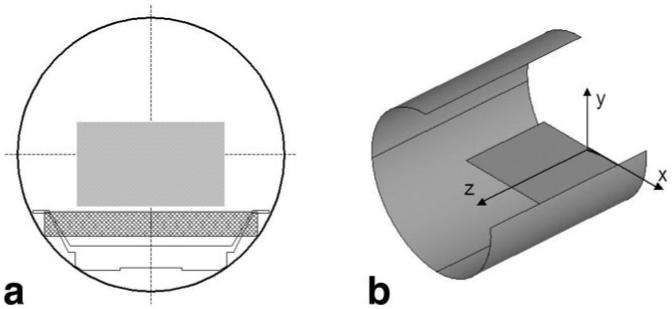
a: Cross section of an existing MR scanner that shows the placement of the local gradient coils in a 60-cm bore and targeted FOV. b: Sketch of a cutout that shows the convention of coordinate axes with respect to local gradients and scanner. Only the positive half of the coil is shown in the z-direction.
We employ a current-density optimization method for the electromagnetic design of the coils wherein current density distributions are modeled by linear combinations of harmonics in two dimensions up to the fourth order (13). For the x-gradient coil, the x-component
| [1] |
of the current density function can be represented as
| [2] |
where Aij are expansion coefficients, wx is the half length of the coil in the x-direction (21 cm), wz is the half length of the coil in the z-direction (30 cm), -wx < x < wx, and -wz < z < wz. Similarly, the x-component of the current density function for the y- and z-gradient coils can be represented respectively as
| [3] |
and
| [4] |
The z-component of the above current density functions can then be found by invoking the need for continuity of current:
| [5] |
In conventional stream-function optimization methods (17,18), it is customary to develop a cost function based on the current density functions and minimize this cost function over the imaging volume with respect to the coefficients of the current density function. In addition to the gradient field linearity, the cost function may incorporate other parameters that require optimization or limitation, such as inductance, generated heat, leakage field, etc. Because of the inexorable loss of gradient strength on all axes as one moves away from the surface of single-sided gradient coils, as compared to conventional cylindrical gradients, significant modification of the standard method of optimization proved essential. If one uses conventional optimization over the imaging volume, the inherent variation of strength in the vertical (y) direction results in poor linearity on all three axes. We remedied this by performing the optimization on a shallow, planar (x-z) volume whose extent in the y-dimension is much smaller than in the x- and z-directions, extending between 1.5 cm and 2.5 cm from the coil surface. This approach ensures the best linearity in any x-z plane within the imaging volume, while the actual strength on any plane changes with the distance from the coil. A detailed description of the technique is given in the Appendix.
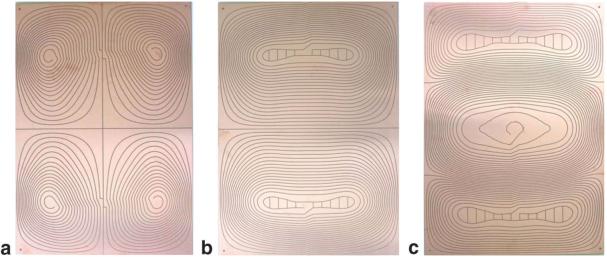
Optimizations were performed in Matlab (The Mathworks, Natick, MA, USA) and run in 60 min on a x86 processor. Figure 2 shows the resulting optimized current patterns for the flat uniplanar x-, y-, and z-gradient coils as regions between the dark lines. As with cylindrical gradient sets (17), contours of the stream function can be directly used as a cutting template to produce gradient coils from conducting sheets, wherein the windings are formed by the space between the lines if the lines are jogged after each turn, as is evident in these photographs. The upper and lower loops that appear on the z-coil arise from the torque minimization term in the cost function and serve to create a reverse torque to compensate for the one created by the central loops.
FIG. 2.
Photographs of the boards for (a) x-, (b) y-, and (c) z-coils. The cuts appear dark and follow the current streamlines with a jog so that the copper between the cuts forms the conducting path. The boards are 42 cm wide and 60 cm long. Additional loops on the z-coil result in torque compensation.
Theoretical magnetic field plots generated by each coil are presented in Fig. 3 and the gradient field plots are shown in Fig. 4. The effects of the unipolar design are evident in the steep falloff in gradient strength with the distance from the coils. At 5 cm above the coils, the average gradient strength generated by the 320 A current available from the standard gradient amplifiers that come with our scanner is approximately 170 mT/m for the x-coil, 230 mT/m for the y-coil, and 325 mT/m for the z-coil. These values translate to efficiencies at this depth of 0.53 mT/m/A for the x-coil, 0.72 mT/m/A for the y-coil, and 1.02 mT/m/A for the z-coil. The coils were designed to handle current levels as high as 640 A at 100% duty cycle (with water cooling able to remove around 50 kW of heat from all three axes), in which case all of these gradient strengths are doubled by the use of newer, stronger amplifiers.
FIG. 3.
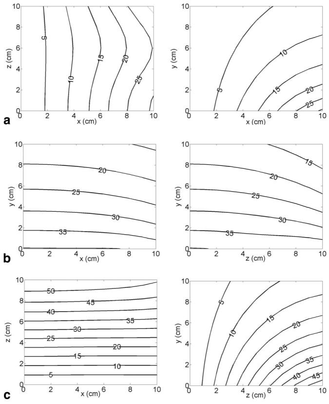
The z-component of the magnetic field (in mT) generated by the x-coil Bz_x (a), the y-coil Bz_y(b), and the z-coil Bz_z (c) at 320 A current. a: Contours on one quadrant of the x-z plane at y = 0 (on the top surface of the coil assembly) are shown at left, with one quadrant of the x-y plane at z = 0 shown at right. b: Contours on one quadrant of the x-y plane at z = 0 are shown at left, with one quadrant of the y-z plane at x = 0 shown at right. c: Contours on one quadrant of the x-z plane at y = 0 (on the top surface of the coil assembly) are shown at left, with one quadrant of the y-z plane at x = 0 shown at right.
FIG. 4.
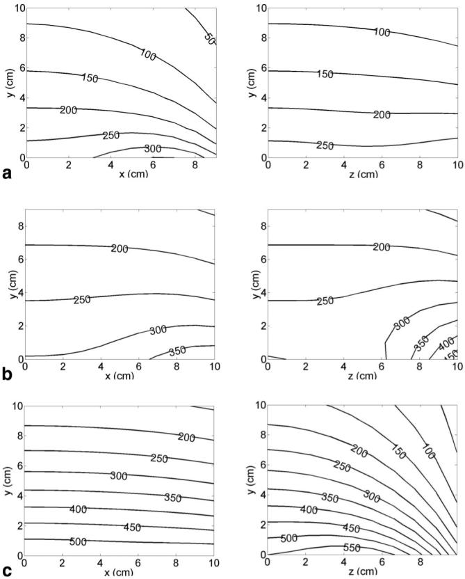
Gradients of the z-component of the magnetic field with respect to (a) x generated by the x-coil , (b) y generated by the y-coil , and (c) z generated by the z-coil , at 320 A current. Gradient values are in mT/m. Contours on one quadrant of the x-y plane at z = 0 (central axial plane) are shown on the left. Contours on one quadrant of the y-z plane at x = 0 (central sagittal plane) are shown on the right.
The predicted electrical properties of each gradient axis are shown in Table 1. Here the copper thickness was 3.2 mm. Although the resistance and inductance values for the y- and z-axes are similar to those of conventional gradient coils, the inductance of the x-axis is much smaller. These values are within the range of the handling capabilities of the available MRI system’s gradient drivers.
Table 1.
Measured and Predicted Electrical Properties of the Coils
| Resistance (mOhm) |
Inductance (μHenry) |
|||
|---|---|---|---|---|
| Measured | Predicted | Measured | Predicted | |
| X | 65 | 75 | 472 | 396 |
| Y | 91 | 99 | 858 | 759 |
| Z | 129 | 123 | 922 | 905 |
Heat load became a limiting factor in attempts to concentrate more power into smaller areas. In the present optimized design, the calculations predicted a heat load of up to 4 kW (RMS) total for each axis at 320 A input, or 16 kW/m2 on average (for these 0.25 m2 boards). Due to the nonuniform current density, local heating in certain small areas could easily exceed three times the average heat generation, or 48 kW/m2. The total heat generation for all three axes was predicted to reach 12 kW RMS for 320 A at 100% duty cycle.
Although the x- and y-gradient coils are inherently torque-balanced, and the optimized z-coil grew reverse loops to null the net torque, in order to ensure safe operation under any conditions, gradient coil failure modes were analyzed to determine the possible maximum forces and torques under a worst-case scenario of a coil shorted in a position that creates the maximum force and/or torque. For example, if the y-gradient is shorted near the middle of the coil, resulting in no current in the top loop to torque-balance the bottom loop, a net torque of 1100 Nt-m at 320 A results. For the x-gradient, if shorts occur at the inner edges of the top-right and bottom-left lobes, resulting in no current in these lobes, then the unbalanced current in the remaining two lobes results in a net torque of 610 Nt-m. For the z-gradient, a short near the bottom of the center lobe can result in unbalanced current in the bottom lobe alone, resulting in a net torque of 1100 Nt-m.
Correcting Image Distortion
In order to maximize the useful FOV of the gradient coil set, compensation for gradient nonlinearity and the fading gradient strength with depth is essential. For conventional cylindrical gradient coils, algorithms for gradient nonlinearity correction have been developed and applied successfully (19,20). These algorithms account for gradient nonlinearity through a truncated power series expansion of the components of the gradient field and exploit the cylindrical geometry to limit the number of nonvanishing terms. In fact, another common approximation employed for gradient nonlinearity compensation in cylindrical systems is to apply the correction one dimension at a time. This is equivalent to assuming that the correction for the z-gradient (or the x-or y-gradient) depends only on the position in the z-direction (or the x-or y-direction, respectively). For 2D imaging this correction is applied successively in the phase and frequency directions, while for 3D imaging this correction is applied successively in all three imaging directions. This procedure (20) goes under the name of GradWarp on GE Signa scanners.
The gradient nonlinearity compensation for single-sided gradients is inherently more involved because of the lack of cylindrical symmetry. In particular, the separation of the unwarping algorithm into successive 1D corrections is not feasible because of the strong dependence of all components of the gradient fields on the distance from the coil plane. Depending on the choice of scan plane, a 2D or 3D algorithm is necessary. We chose to follow a different path to address image correction for gradient nonlinearity. The gradient fields are used in MRI to encode the position, and linearly varying magnetic fields provide a linear mapping between the local Larmor frequency and position of the voxel being imaged. More generally, any monotonic, spatially varying magnetic field allows a unique encoding of voxel position. To extract the physical position of the imaged voxel from the MR data requires now a coordinate transformation from the nonlinear encoding magnetic field (X, Y, Z) to the actual position of the voxel (x, y, z):
| [6] |
We compute this coordinate transformation using the actual field maps of the gradient coils calculated on a 64 × 64 × 64 grid covering a 30 × 20 × 30 cm imaging volume (see Figs. 3 and 4).
The planar gradient coils do not have full cylindrical symmetry; rather, they have a symmetry plane (i.e., the sagittal plane through the isocenter of the magnet). A slice through this plane will not be distorted in the orthogonal direction (x-direction). To completely correct the gradient nonlinearity for a generic scan plane, a volumetric acquisition and a 3D coordinate transformation are necessary, with the acquired volume being sufficiently large to contain the corrected desired slice. However, for the central sagittal plane a 2D in-plane coordinate transformation is sufficient to correct the gradient nonlinearity, allowing single-slice acquisition. For that reason we chose this plane for initial testing of the new gradient nonlinearity correction scheme. The corrected image will be given by:
| [7] |
The dependence of the slice gradient on voxel position in the z-y plane (because of fading gradient strength with distance from the coils) will vary the slice thickness. In other words, as we move away from the gradient coils, voxels of identical prescribed size will in fact become bigger and therefore brighter. The derivative term in the corrected image expression takes this effect into account. For any other imaging plane, the prescribed slice will actually be bent into a “potato chip”-like shape, and a full 3D dataset with a 3D gradient nonlinearity correction algorithm would be necessary to reconstruct the images. In the 3D case, the intensity correction factor would be the Jacobian of the coordinate transformation. We are in the process of including these more general cases in the gradient nonlinearity correction code.
Predicting dB/dt Levels
A potential concern with strong gradients is the possibility of reaching high dB/dt levels, which may lead to PNS. For a given gradient strength, PNS thresholds are expected to be higher for local gradients relative to whole-body cylindrical gradients because of their smaller spatial extent. Figure 5 shows predicted dB/dt contours for this gradient set that were calculated in a coronal plane directly on the surface of the coils, where the dB/dt levels are the highest. Here 1-ms ramps from zero to full scale were assumed. The plots can be scaled inversely assuming different ramp times. In practice, the gradient amplifiers allowed ramps as short as approximately 90 μs for the x-gradient, 180 μs for y, and 200 μs for z. It can be seen from Fig. 5 that maximum dB/dt levels are experienced near the corners of the coils for the x- and y-gradients, and closer to the center of the coil for the z-gradient.
FIG. 5.
Contours of the change in total magnetic-field amplitude with time dB/dt (in T/s), in one quadrant of a coronal plane located on the surface of the gradient assembly, for (a) x-, (b) y-, and (c) z-gradient coils, assuming a gradient ramping time of 1 ms from zero to full strength of 320 A current on each axis. The curves scale directly in proportion to current, and the inverse of the ramp time used.
MATERIALS AND METHODS
The gradient coils are manufactured by mechanically machining the optimized electrical patterns onto plates of 1/8-inch (3.2-mm) thick copper laminated with FR5 grade material, which is stronger and has a higher temperature rating than FR4. In order to pack as many ampere-turns into as limited a space as possible, we pushed the manufacturing methods to their limits, using the smallest cutting head that can machine the pattern reliably, generating only 1.25-mm-wide cuts. The minimum conductor width was limited to 3 mm in the high-turn density regions to avoid extreme local heat generation. Each gradient axis was composed of two overlaid boards connected in series to double the ampereturns in the limited physical volume. The different axes were assembled one over the other.
The large heat load was managed by incorporating a large cooling capacity system and using high-temperature-tolerant materials in the assembly. Sixteen parallel cooling lines were placed strategically between each gradient axis set at locations of high local heat generation to remove the large heat load generated by the boards. Cooling lines were kept short to minimize flow resistance and temperature rise in the coolant in each line, and thereby enable high flow rates for cooling to lower the maximum temperature inside the coil. Since the amount of heat that can be removed from the coil is directly proportional to the temperature difference between the coil and the coolant, it is advantageous to let the coil run as hot as possible. This is limited by the maximum temperature on the coil’s top surface, which must be safe for external contact, and internally by the temperature tolerance of the materials utilized. A two-part epoxy system with a glass transition temperature higher than 150°C was chosen for this purpose.
The gradient coils were assembled dry with mounting brackets, and then vacuum impregnated with the epoxy. The impregnation process anchored the mounting points robustly, enabling safe operation. The coil was instrumented with 12 thermocouples at the locations of highest current density on each board to monitor temperature. Figure 6 shows the epoxy-impregnated coil. A mounting mechanism was designed to safely withstand the maximum force and torque loads calculated by the failure-mode analysis. It is comprised of heavy fiberglass members running along each side of the coils and at two places at the bottom. These members are attached to the coils at the mounting points and bolted to a modified bridge that is normally used to support the patient in the magnet bore.
FIG. 6.
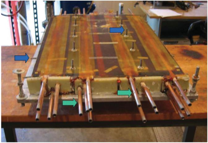
Gradient assembly after epoxy impregnation (shown upside down). The coil assembly is 44 cm wide and 65 cm long. Blue arrows: mounting points; green arrows: cooling lines.
Figure 7 shows the three-axis local gradient coil set mounted in the patient bridge and installed in the 1.5T GE Signa scanner. The coil set is mounted on a modified bridge, which can be easily installed without disturbing the existing cylindrical body gradient system by replacing the existing bridge. Lead connections from the system’s gradient supplies are disengaged from the body gradients and connected to the local gradients. An existing RF body coil was used for RF transmission. Even though the planar gradient coils were located inside the body coil, they did not appear to significantly interfere with the RF field from the coil for the sequences tested. When imaging was performed with phased-array detectors, the array was typically positioned between the subject and the gradient coils. This provided the highest detection sensitivity in regions with the best gradient performance close to the surface, and lower sensitivity in deeper regions with weaker gradients and hence larger voxels as compensation.
FIG. 7.
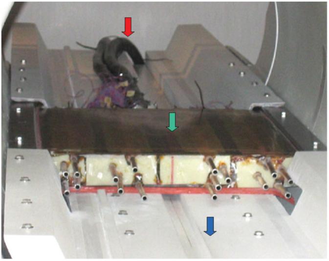
Coil mounted in the patient bridge and installed in the scanner. Red arrow: power leads; green arrow: gradient coils; blue arrow: modified bridge.
MRI studies using spin-echo and gradient-echo pulse sequences were performed on phantoms and normal subjects after informed consent was obtained. Gradient configuration files were modified to reflect the lower inductance values and higher amplitude capabilities of the local gradients. A grid phantom (shown in Fig. 8) was used to measure the gradient strength obtained with the coils by comparing the distances in the acquired image with the actual distances in the phantom. To test the gradient nonlinearity correction algorithm, a sagittal image of the spine of a normal volunteer was acquired and the 2D coordinate transformation and intensity correction was applied to account for nonuniformity of the slice thickness.
FIG. 8.
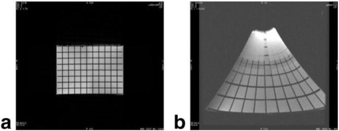
Axial image of a grid phantom with (a) conventional and (b) local gradient coils. Grid spacing is 16 mm.
RESULTS
The measured electrical properties of each gradient coil axis are listed in Table 1 and show excellent agreement with the predicted values. Measurements on the grid phantom showed a maximum gradient strength of 240 mT/m on the x-axis, 270 mT/m on y, and 420 mT/m on z with the existing 1.5T GE Signa system gradient amplifiers, in agreement with the predictions in Fig. 4 at 320 A input. The coil surface was cool to the touch throughout these imaging experiments. On the other hand, internal temperatures reached as high as 100°C after prolonged scanning, which is below the design limit.
Extremity imaging is one application that can benefit from the high resolution in a small imaging volume afforded by these gradients. Figure 9 shows wrist images obtained from a two-channel RF receiver coil with loops above and below the wrist using the body coil for excitation. Here, no distortion correction has been applied, and anatomical detail at 0.2 mm × 0.2 mm resolution is evident in these 2-mm-thick slices.
FIG. 9.
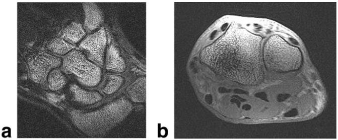
(a) Coronal and (b) axial 3D FGRE wrist images acquired with local gradients. FOV = 10 cm, slice thickness = 2 mm, matrix = 512 × 512 × 56. The wrist was oriented palm-down on the coil.
A spherical geometric-distortion phantom (21) was imaged next to test methods of correcting images for geometric distortion caused by gradient nonlinearities. Uncorrected sagittal spin-echo images of the phantom acquired with the surface gradients and with conventional gradients are shown in Fig. 10a and b. The result of applying the new 2D unwarping algorithm is shown in Fig. 10c. The distortion is significantly ameliorated, although still evident. We attribute the residual distortion to a slight offset of the imaged slice from isocenter. This offset causes the imaged slice to bend and assume a “potato chip” configuration, as can be seen by the difference in imaged regions between the left sides of Fig. 10b and c. In general, minimal positioning errors of the phantom or subject are likely to lead to significant errors in the actual imaged region. This effect is more apparent for large FOVs. The solution to this problem is to scan 3D volumes regardless of scan plane or symmetry of the gradient coil configuration, and reconstruct and correct the slice of interest. Figure 11 shows an implementation of the correction scheme on a sagittal human spine image acquired with the local gradients. The results show that local gradients offer high strength within the relevant imaging volume that potentially can provide (after image distortion correction) high-resolution, anatomically meaningful imaging of the spine.
FIG. 10.
Sagittal images of the spherical geometric-distortion phantom taken with (a) local and (b) conventional gradients. c: Image a corrected by the new unwarping algorithm. FOV = 28 cm, slice thickness = 5 mm, matrix = 256 × 192.
FIG. 11.
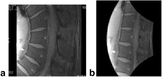
2D spin-echo sagittal spine images acquired with local gradients as (a) acquired and (b) unwarped. FOV = 24 cm, slice thickness = 5 mm, matrix = 256 × 256.
DISCUSSION
The purpose of this study was to design and manufacture a gradient coil set that could provide order-of-magnitude increases in gradient strength and efficiency relative to conventional gradient coils over a limited FOV, and could practically be accommodated in the bore of a conventional MRI scanner and operated using its gradient supplies. We have demonstrated that this can be achieved in a 1.5T system with a single-sided, flat coil configuration on which the patient can lie directly, by optimizing the design for gradient linearity over a restricted volume and accounting for the practical problems of torque and heating. Close proximity of the gradient coils to the patient results in increased coil efficiency. Indeed, the ease of installation into an existing scanner and patient comfort are important advantages of the single-sided, flat configuration over other local gradient coil configurations.
Nevertheless, the flat configuration introduces a major problem of nonlinear gradient fields. We addressed this with a new, true 2D algorithm that corrects images based directly on the calculated field maps over a 30 cm × 20 cm × 30 cm FOV. Although this algorithm is reasonably successful in correcting the highly distorted images, further refinements (i.e., an extension to handle volumetric acquisitions and reconstruction of generic scan planes) are planned for continuing work. The diameter of the spherical geometric distortion phantom used here was 16 cm, which in the y-direction is at least at the resolution limit of practical imaging with this gradient coil. It is therefore more fruitful to focus the unwarping algorithm on the region at y < 8 cm, and increase the discretization on the smaller volume to improve the accuracy of the distortion correction. Another important aspect of the distortion correction is registering the image to the calculated field map. Here we used rough geometric measurements and iterations in the correction calculations for registration, but this is probably best performed using fiducial markers. Furthermore, we plan to increase the resolution of the grid over which we compute the magnetic field gradient generated by the coils. This will allow us to improve the accuracy of the correction algorithm, particularly in regions close to the gradient coils. With these improvements, further advances in image quality are expected in the presence of nonlinear gradient fields, which will directly benefit practical utilization of this system.
We have demonstrated that 240 mT/m gradient strength can be obtained on the x-axis with local gradient coils, which is roughly a factor of 5 improvement over existing state-of the-art cylindrical body gradient coils. However, the 240 mT/m value is limited by the driver power currently available to us, which is somewhat less than that available on MRI systems that produce the highest gradients. Indeed, our coil set is designed for a capability of 500 mT/m in the x- and y-axes, and 1000 mT/m for the z-axis as the higher current drivers become available. In this context our system should provide a full order-of-magnitude increase. Note also that the z-coil efficiency of 1.0 mT/m/A is more than a factor of 2 improvement over the 0.4 mT/m/A quoted previously for a flat z-coil in Ref. 12. The efficiency of local gradients depends on the ability to pack as many field-generating ampere-turns as possible into a limited space close to the patient. During early trade-off optimization studies in this project, basketshaped configurations fitted into the bridge cradle also showed promising results (13). With the latter, some of the turns are pushed to the curved surface, resulting in better utilization of space, although after three coil sets are set, the gain in space at the cradle’s center appears limited.
The mechanical and thermal performance of the coils worked satisfactorily, although we did not test them above the 320 A available. We observed no extraordinary vibration or noise from the coil set while it was secured to its own separate bridge. The thermal stress of repetitive high-duty-cycle MRI using aggressive pulse sequences elicited no noticeable degradation in coil performance over time. As few as four people could exchange bridges, but there would be a clear advantage to a lighter coil set that could be more easily installed.
We acquired images of joints at 0.2 mm × 0.2 mm with a slice thickness of 2 mm, and presently plan to conduct spinal cord DWI and high-speed cardiac MRI to take advantage of the high local gradient strength and slew rate capability of these gradients. Because the imaging volumes are inherently small, the use of high slew rates does not expose the patient to excessively high time-rates-of-change of the magnetic field, and may therefore prove the best approach to high-speed imaging without nerve stimulation in the patient. Nevertheless, we are currently performing safety studies on PNS with these coils, and plan to report the findings soon (22).
ACKNOWLEDGMENTS
We thank John Schenck and Paul Thompson for useful discussions, and Bill Barber and Chuck Goody for assistance with assembly of the gradient coils.
Grant sponsor: National Institutes of Health; Grant number: R01 RR15396.
APPENDIX
The optimization volume is selected to be between -15 and 15 cm in x, between 1.5 and 2.5 cm in y, and between -15 and 15 cm in the z-direction. Note that this is not the imaging volume, but rather the volume on which the optimization calculations are performed. The optimization volume is gridded onto nine equispaced points (here dubbed “field points”) in x and z, and three equispaced points in the y-direction. Similarly, the surface of the gradient boards is discretized into 64 points (“source points”) in the x- and z-directions. The desired gradient field is calculated at each field point ijk. A field-error function Berr is defined as the sum of the absolute differences between calculated and desired fields over all field points:
| [8] |
For the x- and y-coils, the field-error function is the only component of the cost function. A constrained nonlinear optimization was used to find the coefficients of the current density functions (defined in Eqs. [1]-[3]) that minimize the cost function. The total generated heat was used as the constraint in the optimization. This approach allows the optimization to be performed on the field linearity (and net torque) alone while constraining the total generated heat below an acceptable analytically determined value. The total generated heat was calculated as the sum of the local heating computed at each source point as the product of electrical resistance of copper with the square of magnitude of the current density function. Thermal finite element modeling, combined with our past experience, indicates that up to 50 kW of RMS power can be reliably extracted from all the boards with water cooling. A conservative limit of 4 kW per board was therefore chosen for gradient heating. The generated heat was calculated on each iteration, and iterations on coefficients Aij in the current-density functions (Eqs. [1]-[3]) were performed only for those solutions that satisfy this 4 kW condition. During each iteration of the optimization, the magnetic field at each field location was calculated as the field was integrated over each source location. This generated 64 × 64 calculations per field point per iteration. In order to reduce the calculation load, we used a field-sensitivity matrix in which the contribution of each coefficient in the current density function is calculated at each field point by setting the corresponding coefficient to unity and all other coefficients to zero. The field due to a given current density function could then be represented as a linear combination of the field sensitivity matrices for each coefficient.
The optimized current density functions are as follows, for wx = 21 cm and wz = 30 cm. For the x-coil, the coefficients of the current density function (given by Eq. [1]) are
| [9] |
For the y-coil, the coefficients of the current density function (given by Eq. [2]) are
| [10] |
For the z-coil, the coefficients of the current density function (given by Eq. [3]) are
| [11] |
The above coefficients are all in units of Amp/m2. These coefficients correspond to the gradient fields displayed in Fig. 4. Cut patterns for the boards can be extracted from the current density functions as contours evaluated at integer multiples of the design current.
When optimization is performed for gradient linearity only, the current density functions given by Eqs. [1] and [2] for the x- and y-gradient coils generate zero net force and zero net moment in a constant axial magnetic field. The current density function for the z-coil of Eq. [3] generates zero net force. However, it generates a large torque (∼7000 Nt-m) around the x-axis. Therefore, a net torque component NT was added to the cost function that is given by
| [12] |
Here NT is the sum of torque components calculated as the cross product of the current at each source location times the main magnetic field (assumed to be a uniform 1.5T in the z-direction) times the moment arm. The factor of 100 in Eq. [11] was empirically determined to reduce torque to a manageable level (<7 Nt-m) while largely preserving field linearity.
Finally, another departure was made from conventional optimization in the manner in which thermal issues were addressed. In conventional optimization, the rate of heat generation (or equivalently, the electrical resistance) is considered as a component of the cost function, so that the optimization has an inherent trade-off between field linearity and heat generation. In the approach used here, optimization was performed for field linearity and mechanical torque while the rate of heat generation was limited to a ceiling determined by the amount of heat that could be safely dissipated. This decoupled the rate of heat generation from the gradient field linearity, but only up to an acceptable level of thermal performance. This limit, which was set to 4 kW of RMS power per board (or 12 kW RMS for all three axes), was incorporated by means of a limit option in the constrained nonlinear optimization routine.
REFERENCES
- 1.Lutsep HL, Albers GW, DeCrespigny A, Kamat GN, Marks MP, Moseley ME. Clinical utility of diffusion-weighted magnetic resonance imaging in the assessment of ischemic stroke. Ann Neurol. 1997;41:574–580. doi: 10.1002/ana.410410505. [DOI] [PubMed] [Google Scholar]
- 2.Mori S, Crain BJ, Chacko VP, van Zijl PC. Three-dimensional tracking of axonal projections in the brain by magnetic resonance imaging. Ann Neurol. 1999;45:265–269. doi: 10.1002/1531-8249(199902)45:2<265::aid-ana21>3.0.co;2-3. [DOI] [PubMed] [Google Scholar]
- 3.Sakuma H, Takeda K, Higgins CB. Fast magnetic resonance imaging of the heart. Eur J Radiol. 1999;29:101–113. doi: 10.1016/s0720-048x(98)00173-9. [DOI] [PubMed] [Google Scholar]
- 4.Yuan C, Beach KW, Smith LH, Jr, Hatsukami TS. Measurement of atherosclerotic carotid plaque size in vivo using high resolution magnetic resonance imaging. Circulation. 1998;98:2666–2671. doi: 10.1161/01.cir.98.24.2666. [DOI] [PubMed] [Google Scholar]
- 5.Chen Y, Alejski A, Gareau P, Rutt B. High-strength gradient insert coils interfaced to clinical MR scanners; Proceedings of the 10th Annual Meeting of ISMRM; Honolulu, HI, USA. 2002; Abstract 821. [Google Scholar]
- 6.vom Endt A, Kimmlingen R, Riegler J, Eberlein E, Schmitt F. A high-performance head gradient coil for 7T system; Proceedings of the 14th Annual Meeting of ISMRM; Seattle, WA, USA. 2006; Abstract 1370. [Google Scholar]
- 7.Williams G, Fisher B, Huang C, Carpenter T, Hall L. Design of biplanar gradient coils for magnetic resonance imaging of the human torso and limbs. Magn Reson Imaging. 1998;17:739–754. doi: 10.1016/s0730-725x(99)00012-0. [DOI] [PubMed] [Google Scholar]
- 8.Roemer P, Dumoulin C, Souza S, Eisner D. High speed, high field, planar surface gradient assembly for fast imaging; Proceedings of the 7th Annual Meeting of SMRM; San Francisco, CA, USA. 1988; Abstract 134, Works in progress. [Google Scholar]
- 9.Cho Z, Yi J. A novel type of surface gradient coil. J Magn Reson. 1991;94:471–485. [Google Scholar]
- 10.Wong E, Hyde J. The design of surface gradient coils for MRI; Proceedings of the 10th Annual Meeting of SMRM; San Francisco, CA, USA. 1991; Abstract 346. [Google Scholar]
- 11.Shi F, Latour LL, Ludwig R, Sotak CH. A new design for a three-channel surface gradient coil employing a three-dimensional finite element model. Magn Reson Med. 1996;35:596–605. doi: 10.1002/mrm.1910350421. [DOI] [PubMed] [Google Scholar]
- 12.Green D, Bowtell R, Morris P. Uniplanar gradient coils for brain imaging; Proceedings of the 10th Annual Meeting of ISMRM; Honolulu, HI, USA. 2002; Abstract 819. [Google Scholar]
- 13.von Morze C, Bottomley P, Schenck J, Hardy C. A planar gradient set for rapid MR imaging; Proceedings of the 11th Annual Meeting of ISMRM; Toronto, Canada. 2003; Abstract 2420. [Google Scholar]
- 14.Aksel B, Collick B, Marinelli L, Barber W, Bottomley P, Hardy C. Local planar gradients with order-of-magnitude strength and speed advantage; Proceedings of the 14th Annual Meeting of ISMRM; Seattle, WA, USA. 2006; Abstract 780. [Google Scholar]
- 15.Lemdiasov R, Ludwig R, Brevard M, Ferris C. Design and implementation of a uniplanar gradient field coil for magnetic resonance imaging. Concepts Magn Reson Part B (Magn Reson Eng) 2004;20B:17–29. [Google Scholar]
- 16.Petropoulos L. Single gradient coil configuration for MRI systems with orthogonal directed magnetic fields. 5,977,771. U.S. patent. 1999
- 17.Edelstein W, Schenck J. Current streamline method for coil construction. 4,840,700. U.S. patent. 1987
- 18.Turner R. Gradient coil design: a review of methods. Magn Reson Imaging. 1993;11:903–920. doi: 10.1016/0730-725x(93)90209-v. [DOI] [PubMed] [Google Scholar]
- 19.Langlois S, Desvignes M, Constans JM, Revenu M. MRI geometric distortion: a simple approach to correcting the effects of non-linear gradient fields. J Magn Reson Imaging. 1999;9:821–831. doi: 10.1002/(sici)1522-2586(199906)9:6<821::aid-jmri9>3.0.co;2-2. [DOI] [PubMed] [Google Scholar]
- 20.Glover G, Pelc N. Method for correcting image distortion due to gradient nonuniformity. 4591,789. U.S. patent. 1986
- 21.Mallozzi R, Blezek D. Phantom-based data quality control for quantitative imaging of neurological disorders; Proceedings of the 13th Annual Meeting of ISMRM; Miami Beach, FL, USA. 2005; Abstract 1245. [Google Scholar]
- 22.Feldman R, Hardy C, Aksel B, Schenck J, Chronik B. Experimental determination of human peripheral nerve stimulation thresholds in a 3-axis planar gradient system; Proceedings of the 15th Annual Meeting of ISMRM; Berlin, Germany. 2007; Abstract 731. [DOI] [PubMed] [Google Scholar]


