Abstract
This report describes tests of a standard practice for quantifying the performance of implantable middle ear hearing devices (also known as implantable hearing aids). The standard and these tests were initiated by the Food and Drug Administration of the United States Government. The tests involved measurements on two hearing devices, one commercially available and the other home built, that were implanted into ears removed from human cadavers. The tests were conducted to investigate the utility of the practice and its outcome measures: the equivalent ear canal sound pressure transfer function that relates electrically driven middle ear velocities to the equivalent sound pressure needed to produce those velocities, and the maximum effective ear canal sound pressure. The practice calls for measurements in cadaveric ears in order to account for the varied anatomy and function of different human middle ears.
Keywords: Implantable hearing aids, Middle ear transfer function, Sound-induced stapes velocity
Introduction
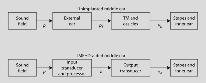
In order to help standardize the testing of implantable middle ear hearing devices (IMEHDs), the Food and Drug Administration of the US government has sponsored the development and testing of a ‘standard practice’ for quantifying IMEHD output [ASTM International F2504−05, 2005]. This report describes tests of the utility of this practice. The tests quantify the output of the IMEHD electrical-mechanical transducer only, and ignore the complications of the IMEHD's ‘front-end’ acoustic-electrical input transducer and processor (fig. 1). These front ends are usually variations of compressive and nonlinear hearing aid amplifiers, and cannot generally be characterized by simple level-independent transfer functions [e.g. Hayes and Cormier, 2000]. Furthermore, IMEHD input transducers and their processors generally have programmable gains and frequency band-passes and consideration of such variations would greatly complicate this report [e.g. Lee et al., 1993]. For purposes of our discussion, the front end includes the sound pickup, signal analyzer, and signal transmitter hardware, i.e. everything exclusive of the electromechanical drive transducer.
Fig. 1.
System diagrams of the unimplanted middle ear and the IMEHD-aided middle ear. In the unimplanted middle ear, the sound field produces a sound pressure p at the entrance to the external ear that is transformed by the external ear to a sound pressure in the ear canal at the tympanic membrane (TM) pT; that sound pressure is then transformed by the unaided middle ear to stapes velocity, vU. In the IMEHD-aided ear, the sound pressure at the entrance to the ear canal is transduced into an electrical signal E by the IMEHD ‘front-end’ input transducer and processor. The electrical signal acts as an input to the IMEHD output transducer that generates an aided stapes velocity vA. In this report, we concentrate on the transformations produced by the normal TM and ossicles vU/pT and the IMEHD output transducer vA/E.
The practice uses the engineering concept of transfer functions to characterize the workings of the middle ear and IMEHD drivers, where a transfer function is the frequency-dependent ratio of the output of a system normalized by its input. As long as the described system is linear, the product of a known input and the system transfer function describe the system output. (The frequency dependence of the defined transfer functions and the measurement variables is assumed and not explicitly included in the following definitions.) The practice calls for measurements of sound-induced unaided stapes velocity vU and IMEHD-aided stapes velocity vA in fresh or thawed-frozen human cadaver ears in which the sound-induced middle ear transfer function, HTV = vU/pT (where pT is the sound pressure in the ear canal at the tympanic membrane), has been demonstrated to fit within a specified ‘normal’ criterion range. The criterion range was computed from a collection of 13 cadaver ear stapes velocity studies reported by laboratories throughout the world [Rosowski et al., 2004] (fig. 2). The center of the criterion range is determined by the mean of all of the included study means, while the upper and lower boundaries of the criteria range are defined by twice the standard deviation of the different study means. If all of the study means were independent samples of identical sample size of the same population, the standard deviation of their means would be equivalent to the standard error of the population mean for that sample size. The upper and lower bounds of figure 2b represent 95% confidence limits around the population mean based on the above assumptions.
Fig. 2.
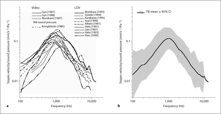
a Nine laser-Doppler measurements [Nishihara et al., 1993; Goode et al., 1994; Kurokawa and Goode, 1995; Asai et al., 1999; Voss et al., 2000; Aibara et al., 2001; Hato et al., 2001, 2003; Gan et al., 2001] along with 3 videostroboscopic measurements [Gyo et al., 1987; Gyo and Goode, 1988; Murakami et al., 1997] and 1 round window sound pressure estimate [Kringlebotn and Gundersen, 1985] of stapes velocity in cadaver ears. The laser measurements have been corrected for observation angle using a cos correction. b The grand mean of the 13 study means and twice the standard deviation of the study means.
Once the middle ear transfer function, HTV, of a particular cadaver ear has been demonstrated to fall within the criteria range, the IMEHD electromechanical transducer is implanted and measurements are made of (a) the sound-induced stapes velocity with the IMEHD in place and (b) the IMEHD-aided velocity of the stapes or electro-vibrational transfer function, HEV = vA/E, where E is the electrical voltage input to the IMEHD output transducer. Comparisons of the sound-induced stapes velocity before and after IMEHD implantation are used to compute ΔHTV, the change in middle ear transfer function due to insertion of the IMEHD:
| (Eq. 1) |
Comparisons of the IMEHD-aided stapes velocity and the sound-induced stapes velocity prior to implantation are used to compute HET, the equivalent ear canal sound pressure transfer function:
| (Eq. 2) |
The maximum equivalent ear canal sound pressure, pEmax, produced by the IMEHD is computed from the product of HET and Emax, the maximal electrical signal deliverable to the IMEHD output transducer. The maximum equivalent sound pressure level, LEmax, is then computed by:
| (Eq. 3) |
Methods
Preparation of the Cadaver Ears and Stapes Velocity Measurements
Thirteen fresh cadaver ears (ranging in age from 40 to 90 years) were used in studies of either a commercially available implantable device (IMEHD-A), or a home-built electromagnetic stimulator (IMEHD-B). All of the extracted ears appeared normal on otoscopic inspection. The preparation and measurements methods are as described in earlier work [e.g. Chien et al., 2006]. Briefly, the ear was removed from the cadaver as a temporal bone plug using the techniques described by Schuknecht [1974]. Such plugs include the entire inner ear, tympanic membrane and ossicles, but only include a fraction of the mastoid air spaces and the cartilaginous ear canal. The cartilaginous canal remnant was cleaned and shortened and a posterior tympanotomy with removal of the facial nerve used to widely open the facial recess. The stapedius tendon was sectioned to reveal the posterior crus. A small piece of reflective tape (0.1 mm2) was placed on the posterior crus. An Etymotic ER3-A earphone coupled to a large volume sound coupler and microphone assembly was sealed to a speculum and held in the cartilaginous ear canal such that the microphone probe tube was within a few mm of the center of the tympanic membrane. A laser-Doppler vibrometer (CLV-1000, Polytec-PI) mounted under an operating microscope with a joystick-controlled aiming prism was used to make measurements of stapes velocity. The beam was focused on the stapes reflector with a beam angle of 30−50° relative to the piston-like axis of stapes motion.
The stapes velocity was measured in response to: (a) sound stimulation prior to IMEHD implantation to compute the preimplantation middle ear transfer function, HTV = vU/pT; (b) sound stimulation after implantation of the IMEHD electromechanical transducer to compute the postimplantation middle ear transfer function, , and (c) electric stimulation E of the IMEHD transducer to compute the aided electrovibrational transfer function, HEV = vA/E. Measurements of velocity were made with stimulus frequencies of 150−10,000 Hz at a frequency density of three points per octave. All of the velocity measurements were corrected for the measurement angle using a cos correction.
The Implantable Middle Ear Hearing Devices
IMEHD-A, which drives the incus, was a commercially available implantable hearing aid drive donated by one manufacturer. The device was implanted following the manufacturer's specification, and periodic tests of the device's output and electrical impedance were performed to demonstrate the device was within the manufacturer's normal specifications. Two devices supplied by the manufacturer were used in 11 cadaver ears with each device used a number of times.
IMEHD-B was a simple magnetic drive system, with a 0.08-gram permanent magnetic disk placed on the umbo driven by an electromagnetic coil placed within the ear canal at a distance of 1 mm from the disk. The coil consisted of a 2-mm-diameter wooden rod around which was wound 300 turns of low-resistance wire. The coil was placed via an opening made in the anterior bony ear canal that was closed during sound stimulation, such that the major axis of the coil was perpendicular to the surface of the disk and the tympanic membrane near the umbo, and the tip of the coil was within 1 mm of the magnet. As will be demonstrated, IMEHD-B is not very efficacious for delivering energy to the middle ear, but the purpose of this paper is to test the proposed standard practice for quantifying IMEHD output and not test individual devices.
Results and Discussion
Meeting the Normal Temporal Bone Criteria
The criteria for normal stapes velocity transfer function in cadaver ears were found to be too restrictive, and we accepted several ears whose response was marginally within the criterion range. Of the 11 cadaver ears used in evaluating IMEHD-A, only 6 had middle ear transfer functions that fit within the criterion range published in the practice, and these 6 included 2 ears in which the velocity was of lower magnitude than the published criteria at a single frequency point (fig. 3). In testing IMEHD-B, 5 of 6 ears were judged to meet the criteria; though again, 2 of the 5 had middle ear transfer function magnitudes that were outside the criterion range at a single frequency point, and a 3rd ear (TB5) had velocities that were just outside the lower edge of the criterion range at frequencies above 1000 Hz. We were unable to determine a structural or methodological correlate (e.g. age at death) to the wide variability in middle ear response. Such variability has been described previously in temporal bone studies [e.g. Kringlebotn and Gundersen, 1985] and is also consistent with the wide variability in ossicular velocities measured in live humans with normal hearing [Whittemore et al., 2004]. It should be noted that during the criterion measurements, not only were the IMEHD implants not present, but the ear canal coil necessary to drive IMEHD-B was not in place.
Fig. 3.
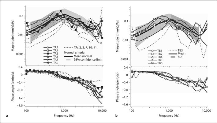
Measurements of middle ear transfer function, HTV, in test ears compared to the ‘normal’ criterion range. a Comparison of the 11 cadaver ears used to test IMEHD-A. b The 6 cadaver ears used to test IMEHD-B. The magnitude of the transfer function and the criterion are illustrated in the upper panels. The phases of the transfer functions are illustrated in the lower panels. a Measurements in 6 of the 11 ears used for testing IMEHD-A were judged to fit within the criteria (black lines and symbols). Measurements in 5 ears were clearly outside the magnitude criteria at multiple frequencies (dashed gray lines). Comparisons of the phases of the velocity transfer function show little differences in the pattern of those ears that did or did not fit within the magnitude criterion. b Measurements in 5 of the 6 ears used for testing IMEHD-B were judged to fit within the criteria (black lines and symbols).
Effect of Insertion of the IMEHD on the Middle Ear's Response to Sound: ΔHTV
The change in middle ear sound transmission that results from the insertion of IMEHD-A and -B into the middle ear is illustrated in figures 4 and 5. IMEHD-A implantation was associated with increases in sound-induced middle ear transfer function, HTV, of as much as 16 dB at the higher frequencies in some ears and decreases of 10−20 dB in other ears at other frequencies (fig. 4a). There is little difference in the ratios determined in the 6 ears that met the ‘normal’ inclusion criterion and 4 that did not (fig. 4a). (One ear, included in fig. 3 , that did not meet the ‘normal’ criteria, TA7, was damaged during IMEHD insertion, and is not illustrated in later figures.)
Fig. 4.
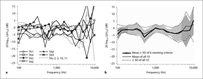
Effect of IMEHD-A insertion on the sound-induced response of the middle ear: ΔHTV. a 20 log10 (ΔHTV) in 10 ears with IMEHD-A inserted. The solid lines and markers are the results from 6 ears that were judged to meet the inclusion criteria. b Means and standard deviations of the 6 ears that met the inclusion criteria and all 10 ears.
Fig. 5.
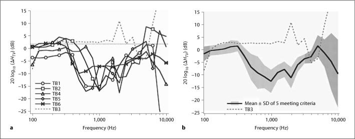
Effect of IMEHD-B insertion on the sound-induced response of the middle ear: ΔHTV. a 20 log10 (ΔHTV) in 6 ears with IMEHD-B inserted. The solid lines and markers are the results from 5 ears that were judged to meet the inclusion criteria. b Means and standard deviations of the 5 ears that met the inclusion criteria.
The lack of segregation of the ΔHTV determined in the ears that met and did not meet criteria is also illustrated in figure 4b where the mean and standard deviations of ΔHTV for the six that met criteria and the entire population of 10 are compared. On average, the insertion of IMEHD-A caused a 2−3-dB reduction in sound-induced stapes velocity that was roughly independent of frequency.
The individual ΔHTV measurements in 6 ears implanted with IMEHD-B and the mean and standard deviation in the 5 cadaver ears that were judged to meet criteria are plotted in figure 5. Unlike IMEHD-A, which introduced little change in the direct-sound-induced sensitivity of the middle ear, IMEHD-B introduced a 5- to 15-dB loss in the sensitivity to sound between 500 and 3000 Hz. Similar losses have been reported after the placement of weights on the tympanic membrane and ossicular chain [Lynch, 1981; Gan et al., 2001]. The ear that did not meet criterion, ear TB3, had a low initial HTV, either because of increased stiffness or losses in ossicular transmission, and exhibited a ΔHTV that is close to 0 dB, indicative of a smaller effect of IMEHD-B implantation in that ear. An increased stiffness of the middle ear or increased ossicular flexibility might have protected that ear from an additional decrease in function related to the placement of IMEHD-B.
The Electrovibrational Transfer Function, HEV
The velocities of the stapes that result from electrical stimulation of the IMEHDs are illustrated in figures 6 and 7 , which show plots of the electrovibrational transfer function, HEV, for IMEHD-A (fig. 6) and IMEHD-B (fig. 7).
Fig. 6.
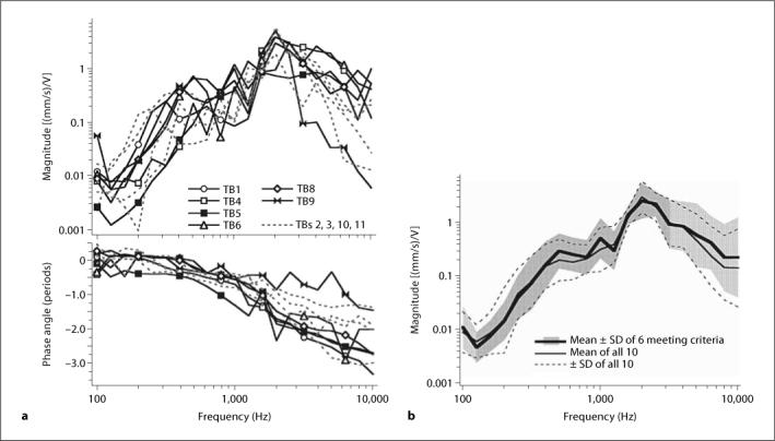
The individual and mean electrovibrational transfer function, HEV, of IMEHD-A. a The magnitude and angle of HEV for the 10 ears in which it was measured. The data from ears that did not meet the inclusion criterion are illustrated by gray dashed lines. The phase angle represents the difference between the phases of the measured velocity and the electrical stimulus. b The mean magnitude and standard deviations of 6 ears that met the criterion and the full set of 10 ears with successful implantation of IMEHD-A.
Fig. 7.
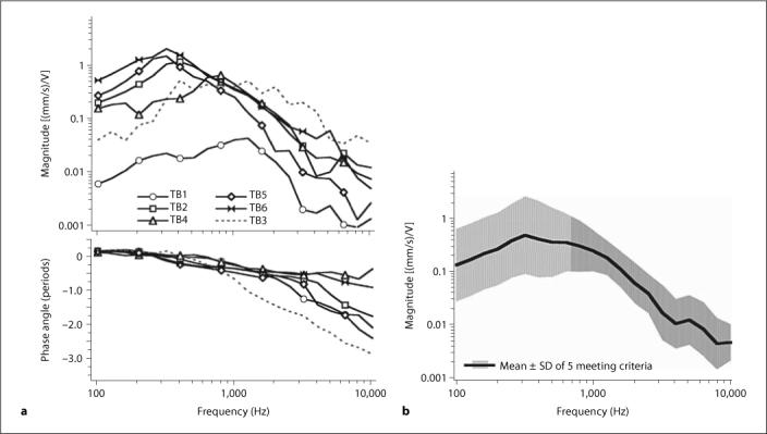
The individual and mean electrovibrational transfer function HEV of IMEHD-B. a The magnitude and angle of HEV for the 6 ears in which it was measured. The data from ear 3, which did not meet the inclusion criterion, are illustrated by gray dashed lines. The phase angle represents the difference between the phases of the measured velocity and the electrical stimulus. b The mean magnitude and standard deviations of 5 ears that met the criterion.
For IMEHD-A, the data show that constant voltage stimuli at frequencies >1000 Hz produce larger velocities than at lower frequencies (fig. 6). The phase angles (fig. 6a) suggest an increasing delay between the velocity and the electrical stimulus with about 2.5 periods of phase accumulation occurring by 10,000 Hz. There are no regular differences between HEV measured in ears that did or did not meet the criterion. The order of magnitude variation in the magnitude of HEV between individuals is a little smaller than the between-individual variations observed in the acoustically driven HTV (fig. 3a). The lack of difference between the HEV measured in ears that did or did not meet the inclusion criteria is emphasized by the similarity of the mean HEV magnitude determined from all 10 ears and the mean of the subset of 6 that met the criteria (fig. 6b).
Unlike IMEHD-A, electrical stimulation of IMEHD-B produced larger velocities at frequencies <1000 Hz than at higher frequencies (fig. 7), although the magnitude of the largest evoked velocities are similar (fig. 6, 7). The phase angles resulting from IMEHD-B stimulation (fig. 7a) also suggest an increasing delay between the velocity and the electrical stimulus, but the magnitude of the delay is smaller than that observed in IMEHD-A. While the small size of the sample does not allow us to reach firm conclusions, the IMEHD-B-evoked HEV appears more variable than that of IMEHD-A. This increased variability is seen in the HEV determined in TB1 in which the electrically driven velocity is a factor of 30 smaller than the velocities observed in the other ears that met the criterion for normal function. The one bone that did not meet criterion levels (TB3) had an electrically driven velocity that was more similar to the other 4 ears that met the criteria.
The Equivalent Ear Canal Sound Pressure Transfer Function, HET
As defined by equation 2, the equivalent ear canal sound pressure transfer function is the ratio of the electrovibrational transfer function and the middle ear transfer function: HET = HEV/HTV. If the middle ear and the IMEHD are linear, HET describes the ear canal sound pressure associated with the unaided stapes velocity vU that equals the electrically aided stapes velocity vA and has units of pressure per volt.
The HETscomputed for the two IMEHD devices (fig. 8) show similar peak equivalent sound pressures but are greatly different in their frequency dependence, which reflects the different frequency dependences observed in the electrically evoked stapes velocity in the two IMEHDs (fig. 6, 7). For a given input voltage of differing frequency, IMEHD-A produces the largest equivalent sound pressure near 2000 Hz, with sound pressures a factor of 10−100 times smaller at frequencies of 1000 Hz and lower. IMEHD-B, on the other hand, produces its largest equivalent ear canal sound pressures at frequencies of 500 Hz and lower and the equivalent sound pressure generally falls off at about an order of magnitude per decade at higher frequencies.
Fig. 8.
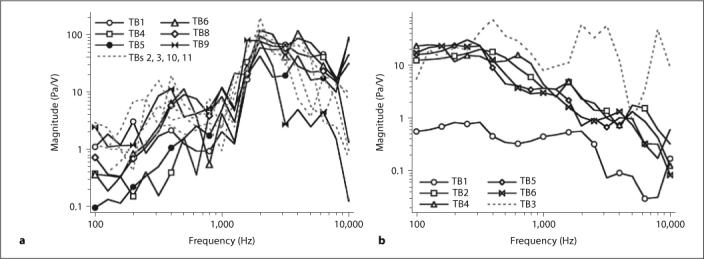
The equivalent ear canal sound pressure transfer function, HET, in IMEHD-A (a), and in IMEHD-B (b). The equivalent ear canal sound pressure per volt of electrical stimulation as defined in equation 2 is plotted as a function of frequency. Note that the vertical scales of the two plots differ by a factor of 5.
There is a significant difference in the inter-ear variability of this measure in the two IMEHDs. The magnitudes of the HETs at any one frequency determined for IMEHD-A vary over an order of magnitude and appear independent of whether an ear met the inclusion criteria or not (fig. 8a). The magnitudes of the HETs determined for IMEHD-B vary little in 4 ears that met the inclusion criteria, are about an order of magnitude smaller in TB1 that also met criteria, and are a factor of 2−10 larger in TB3 that did not meet criteria. The larger magnitude of HET with IMEHD-B in TB3 is a consequence of the combination of the low magnitude of its unaided transfer function HTV (fig. 3b) and its relatively normal aided transfer function HEV (fig. 7a). In contrast, the lower HET magnitude seen with IMEHD-B in TB1 is a direct consequence of the lower magnitude of its electrically driven aided transfer function HEV (fig. 7a).
The Maximum Equivalent Sound Pressure Level, LEmax
The maximum equivalent sound pressure level, LEmax, with units of dB SPL, is an attempt to estimate the maximum output of an IMEHD electrical-mechanical transducer in terms that are meaningful to hearing clinicians. The LEmax is described in equation 3 and depends on knowledge of the equivalent ear canal sound pressure transfer function, HET, and Emax, the maximum electrical drive to the transducer. Such a calculation assumes that HET is linear over the input range less than Emax, and that electrical stimulations larger than Emax produce either nonlinear output growth, distorted output or damage to the IMEHD transducer.
The determination of Emax is not necessarily straightforward and has not been specified in the practice. (The assumption is that Emax would be specified by the manufacturers.) For IMEHD-A, we chose an Emax of 0.1-volt input, because larger voltages produced significant distortion (total harmonic distortion >1% of the fundamental response) at frequencies <600 Hz; however, larger voltages at higher frequencies did not produce significant distortion. (The frequency-dependence of the distortion limit suggests that Emax can depend on frequency. In the case of IMEHD-A, allowing a frequency-dependent Emax will alter the computation of LEmax leading to larger LEmax at frequencies above 500 Hz.) The determination of Emax for IMEHD-B was simpler: input voltages larger than 1 V led to overheating and damage of the coil, where the overheating process did not depend on stimulus frequency.
According to figure 9a, at frequencies <1000 Hz a 0.1-volt stimulus to IMEHD-A produced a stapes velocity equivalent to that produced by an 80-dB SPL ear canal sound stimulus. Between 2000 and 4000 Hz, a 0.1-volt drive produced an equivalent sound pressure of 100−110 dB SPL. This pattern was observed in ears that did or did not meet the inclusion criteria. (Again, a more refined definition of Emax could lead to increases in maximum equivalent sound pressure level.) IMEHD-B, on the other hand, was most effective at frequencies below 500 Hz, where a maximum 1-volt stimulus produced a stapes velocity equivalent to that produced by an ear canal sound pressure of 115 dB SPL. At higher frequencies, the equivalent sound pressure falls off at about 20 dB/decade. The equivalent sound pressure was larger in TB3, which had a sound-induced stapes velocity that was too small to meet the inclusion criteria (fig. 3b); the small sound-induced unaided stapes velocity that led to exclusion of the bone is directly related to its larger LEmax.
Fig. 9.
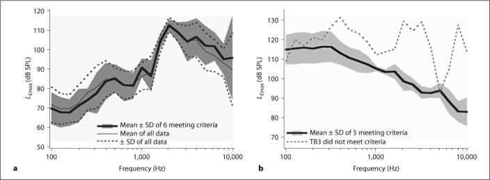
The mean maximum equivalent ear canal sound pressure level, LEmax, as defined in equation 3 is plotted as a function of frequency. LEmax depends on the maximal electrical input to the IMEHD electromechanical transducer. a The mean LEmax for IMEHD-A (assuming an Emax of 0.1 V) for the 6 ears that met the inclusion criteria and the entire set of 10 ears. b The mean LEmax for IMEHD-B (assuming an Emax of 1 V) for the 5 cases that met the inclusion criteria and a 6th ear that did not.
The quantification of LEmax for IMEHD-A and -B permits a comparison of the efficacy of the two devices. One metric of comparison is the largest magnitude of LEmax at any frequency, where both IMEHD-A and -B are capable of producing outputs equivalent to 110−115 dB SPL in the ear canal. However, in IMEHD-A the maximum occurs at 2000 Hz, while in IMEHD-B the maximum is obtained at frequencies less than 500 Hz. We can also estimate the bandwidth of the LEmax output function, where following the ANSI standard for hearing aid bandwidth estimation, we average the magnitude of LEmax at 1000, 1600 and 2500 Hz and then estimate the range of frequencies where LEmax is greater than this average minus 20 dB. The bandwidth for IMEHD-A is between 800 Hz and 10,000 Hz, while the bandwidth for IMEHD-B is between 100 Hz and 8000 Hz. The differences in bandwidth reflect the differences in the frequency dependence of LEmax.
A factor that can also contribute to the efficacy of a battery-powered device like an IMEHD is the power consumption at maximal output, where average electrical power can be computed from the square of the rms input voltage divided by the resistive component of the electrical input impedance of the IMEHD electromechanical transducer. IMEHD-A has a broadband input impedance that is real with a magnitude of about 50 Ω, and therefore a maximal input of 0.1 rms V is associated with a power consumption of about 0.2 mW. IMEHD-B has a broadband input impedance that is real with a magnitude 5 Ω, and therefore a maximal input of 1 rms V is associated with a power consumption of about 0.2 W. At maximal input, where IMEHD-A and -B produce roughly equal amounts of sound pressure, IMEHD-A consumes 1/1000th of the power IMEHD-B consumes.
Estimates of Distortion
It is sometimes claimed that electrical-mechanical IMEHD devices that produce a simple mechanical output are not subject to the same level of distortion seen in electroacoustic hearing devices. We, therefore, investigated the distortion present in the stapes velocities evoked by our earphones and the commercially available device IMEHD-A.
Continuous sinusoidal stimuli of frequencies of 990 or 2002 Hz were played either through the ER3A earphone in the unimplanted ear or used as the input stimulus to IMEHD-A. The stimulus levels were selected to produce similar velocity magnitudes with the two stimulators. Figure 10a, c show spectra determined from the averaged response to IMEHD stimulation, while figure 10b, d show spectra of the averaged response to acoustic stimulation. The stimulus frequency-equivalent sound pressures associated with these velocity response levels are 90 dB SPL at 900 Hz and 115 dB SPL at 2000 Hz. All four spectra show signs of harmonic distortion at some combination of 2, 3 or 4 times the stimulus frequency. In all cases, the magnitude of the distortion is 2−3 orders of magnitude below the response to the stimulus frequency. The similarity of the distortion magnitudes produced by the two drives suggest the generator of the distortion is within the middle ear rather than in the individual drivers. (Such a low distortion level at 90 dB is consistent with measurements of nonlinear growth of the fundamental component of the middle ear's response to stimulus levels that are 40 dB larger.) Spectra of the ear canal sound pressure during acoustic stimulation (not shown) illustrate comparable distortion levels. These distortion tests demonstrate that (a) harmonic distortion can be seen in middle ears driven by IMEHD devices, and (b) the level of distortion associated with mechanical middle ear drives can be similar to that associated with acoustical drives.
Fig. 10.
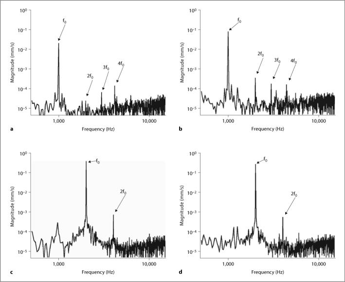
a, c Spectra of the stapes velocity when driven by IMEHD-A with tonal stimuli of 990 or 2002 Hz (0.1 V), respectively. b, d Spectra of the stapes velocity before implantation when acoustically driven by our earphone with stimuli of 990 or 2002 Hz (1 V), respectively. The stimulus levels elicit similar levels of stapes response from the IMEHD and the earphone. The response to the stimulus frequency is labeled fo. Harmonic responses are at 2, 3 or 4 fo.
Conclusions
The ASTM International F2504−05 Standard Practice is a viable method for quantifying the output of IMEHDs while accounting for interindividual variations in middle ear form and function. The tests described here allow quantification of IMEHD responses without the complications of the nonlinearity and variable bandwidth of the input transducer and hearing aid processors used as front ends in these devices.
The standard practice's criteria for determining the normal functioning of individual test ears appear too strict. We modified the criteria by permitting small deviations (less than a factor of 2) above and below criterion range in narrow frequency ranges and widening the range by 20%. The interrelationship between the abnormally high equivalent level output of TB3 (fig. 9b) and its much lower than criterion acoustically driven stapes velocity (fig. 3b) point out the necessity for such criteria.
IMEHD-A, which drives the incus, has a small effect on the unaided middle ear transfer function (fig. 4a) and has a frequency-dependent output such that a ‘maximal’ electrical 0.1-volt input to the IMEHD electromechanical transducer produces equivalent ear canal sound pressure levels of 80 dB SPL below 1000 Hz and 100−115 dB SPL above 2000 Hz (fig. 9a). The band pass of the average maximum effective sound pressure level function is 800−10,000 Hz.
IMEHD-B, which involves the placement of an 0.08-gram permanent magnet on the umbo, produces a 5- to 15-dB loss in the unaided middle ear transfer function (fig. 4b) in the middle frequencies, and produces a 115-dB SPL equivalent ear canal sound pressure level at frequencies below 500 Hz but rolls off at higher frequencies (fig. 9b). The band pass of the average maximum effective sound pressure level function is 100−8000 Hz.
IMEHD-A is several orders of magnitude more power efficient than the simpler home-made IMEHD-B.
IMEHD-A has output measures that are relatively insensitive to variations in the preimplantation stapes velocity transfer characteristics. The output measures of IMEHD-B are sensitive to variations in the preimplantation stapes velocity. The sensitivity of IMEHD-B to normal middle ear function may be related to the additional load that the 0.08-gram magnet of this device placed on the middle ear.
IMEHD-A, the commercially available device, and the ER3-A earphone we used are both associated with low-to-moderate levels of distortion in the middle ear output when they generate stapes motions that are equivalent to those associated with sound pressures of 90−115 dB SPL. Such a level of distortion is consistent with previous measures that show nonlinear growth of middle ear output at sound levels of 120 dB SPL.
Acknowledgements
This work was funded by a contract from the Food and Drug Administration. The standard practice is published by ASTM International of Philadelphia, Pa., USA. The ASTM International ‘Implantable Hearing Devices’ subcommittee F04.37 is responsible for the content of the practice. We wish to thank the IMEHD manufacturer who lent us the test devices. We also wish to acknowledge the staff of the Eaton-Peabody Laboratory, partic ularly Melissa Wood. Special thanks go to Ishmael Stefanov and Chris Scarpino who helped design and build the home-built IMEHD device.
References
- Aibara R, Welsh JT, Puria S, Goode RL. Human middle-ear sound transfer function and cochlear input impedance. Hear Res. 2001;152:100–109. doi: 10.1016/s0378-5955(00)00240-9. [DOI] [PubMed] [Google Scholar]
- Asai M, Huber AM, Goode RL. Analysis of the best site on the stapes footplate for ossicular chain reconstruction. Acta Otolar yngol. 1999;119:356–361. doi: 10.1080/00016489950181396. [DOI] [PubMed] [Google Scholar]
- ASTM International F2504−05 . Standard Practice for Describing System Output of Implantable Middle Ear Hearing Devices. ASTM; Philadelphia: 2005. [Google Scholar]
- Chien W, Ravicz ME, Merchant SN, Rosowski JJ. The effect of methodological differences in the measurement of stapes motion in live and cadaver ears. Audiol Neurotol. 2006;11:183–197. doi: 10.1159/000091815. [DOI] [PMC free article] [PubMed] [Google Scholar]
- Gan RZ, Dyer RK, Wood MW, Dormer KJ. Mass loading on the ossicles and middle ear function. Ann Otol Rhinol Laryngol. 2001;110:478–485. doi: 10.1177/000348940111000515. [DOI] [PubMed] [Google Scholar]
- Goode RL, Killion M, Nakamura K, Nishihara S. New knowledge about the function of the human middle ear: development of an improved analog model. Am J Otol. 1994;15:145–154. [PubMed] [Google Scholar]
- Gyo K, Aritomo H, Goode RL. Measurement of the ossicular vibration ratio in human temporal bones by use of a video measuring system. Acta Otolaryngol. 1987;103:87–95. doi: 10.3109/00016488709134702. [DOI] [PubMed] [Google Scholar]
- Gyo K, Goode RL. Measurement of stapes vibration driven by the ceramic vibrator of a middle ear implant – human temporal bone experiments. Middle ear implant: implantable hearing aids. Adv Audiol. 1988;4:107–116. [Google Scholar]
- Hato N, Stenfelt S, Goode RL. Three-dimensional stapes footplate motion in human temporal bones. Audiol Neurootol. 2003;8:140–152. doi: 10.1159/000069475. [DOI] [PubMed] [Google Scholar]
- Hato N, Welsh JT, Goode RL, Stenfelt S. Acoustic role of the buttress and the posterior ligament in human temporal bones. Otolaryngol HNS. 2001;124:274–278. doi: 10.1067/mhn.2001.113664. [DOI] [PubMed] [Google Scholar]
- Hayes DE, Cormier KL. Double blind comparison of three hearing aid circuits with new hearing aid users. Scand Audiol. 2000;29:10–19. doi: 10.1080/010503900424552. [DOI] [PubMed] [Google Scholar]
- Kringlebotn M, Gundersen T. Frequency characteristics of the middle ear. J Acoust Soc Am. 1985;77:159–164. doi: 10.1121/1.392280. [DOI] [PubMed] [Google Scholar]
- Kurokawa H, Goode RL. Sound pressure gain produced by the human middle ear. Am J Otol. 1995;113:349–355. doi: 10.1016/S0194-59989570067-6. [DOI] [PubMed] [Google Scholar]
- Lee LW, Humes LE, Wilde G. Evaluating performance with high-frequency emphasis amplification. J Am Acad Audiol. 1993;4:91–97. [PubMed] [Google Scholar]
- Lynch TJ., III . ScD Thesis. Mass.; Cambridge: 1981. Signal Processing by the Cat Middle Ear: Admittance and Transmission, Measurements and Models. [Google Scholar]
- Murakami S, Gyo K, Goode RL. Effect of middle ear pressure change on middle-ear mechanics. Acta Otolaryngol. 1997;117:390–395. doi: 10.3109/00016489709113411. [DOI] [PubMed] [Google Scholar]
- Nishihara S, Aritomo H, Goode RL. Effect of changes in mass on middle ear function. Otolaryngol HNS. 1993;109:899–910. doi: 10.1177/019459989310900520. [DOI] [PubMed] [Google Scholar]
- Rosowski JJ, Huber AM, Ravicz ME, Goode RL. Are temporal bones useful models of human middle-ear mechanics? Abstracts of the Twenty-Seventh Meeting of the Association for Research in Otolaryngology. 2004:275. [Google Scholar]
- Schuknecht HF. Pathology of the Ear. Harvard University Press; Cambridge: 1974. [Google Scholar]
- Whittemore KR, Merchant SN, Poon BB, Rosowski JJ. A normative study of tympanic membrane motion in humans using a laser Doppler vibrometer (LDV). Hear Res. 2004;187:85–104. doi: 10.1016/s0378-5955(03)00332-0. [DOI] [PubMed] [Google Scholar]
- Voss SE, Rosowski JJ, Merchant SN, Peake WT. Acoustic response of the human middle ear. Hear Res. 2000;150:43–69. doi: 10.1016/s0378-5955(00)00177-5. [DOI] [PubMed] [Google Scholar]


