

Abstract
The mechanical and structural properties of a surface play an important role in determining the morphology of attached cells, and ultimately their cellular functions. As such, mechanical and structural integrity are important design parameters for a tissue scaffold. Electrospun fibrous meshes are widely used in tissue engineering. When in contact with electrospun scaffolds, cells see the individual micro- or nanofibres as their immediate microenvironment. In this study, tensile testing of single electrospun nanofibres composed of poly(ε-caprolactone) (PCL), and its copolymer, poly(caprolactone-co-ethyl ethylene phosphate) (PCLEEP), revealed a size effect in the Young's modulus, E, and tensile strength, σT. Both strength and stiffness increase as the fibre diameter decreases from bulk (∼5 μm) into the nanometre region (200–300 nm). In particular, E and σT of individual PCL nanofibres were at least two-fold and an order of magnitude higher than that of PCL film, respectively. PCL films were observed to have more pronounced crystallographic texture than the nanofibres; however no difference in crystalline fraction, perfection, or texture was detected among the various fibres. When drugs were encapsulated into single PCLEEP fibres, mechanical properties were enhanced with 1–20 wt% of loaded retinoic acid, but weakened by 10–20 wt% of encapsulated bovine serum albumin. This understanding of the effect of size and drug and protein encapsulation on the mechanical properties of electrospun fibres may help in the optimization of tissue scaffold design that combines biochemical and biomechanical cues for tissue regeneration.
1. Introduction
The application of polymeric nanofibres to tissue engineering has gained immense popularity over the past few years. Fibrous meshes composed of nanofibres have a large surface area-to-volume ratio allowing efficient mass transport and cell attachment to the meshes. Techniques such as phase separation [1], self-assembly [2] and electrospinning have therefore been devised to fabricate nanofibres. Among these techniques, electrospinning is the most versatile and has received the most widespread attention.
One of the main advantages of using electrospinning is the simplicity of mass-producing fibres with diameters in the sub-micron to micron range. A scaffold made up of fibres of such dimensions can in principle better mimic the structure and morphology of the extracellular matrix (ECM) component in the body, and is believed to be able to provide topographical cues to control and enhance tissue regeneration [3, 4]. In addition, electrospun scaffolds may also be biofunctionalized through the inclusion of drugs and proteins to provide biochemical cues [5–9]. Cells that are in close contact with these biofunctionalized scaffolds may then respond to the biochemical cues through interaction of the cell membrane receptors with the fibre-immobilized ligands [10] or through sustained release of the encapsulated drug.
Whereas soluble factors have been regarded as the prime drivers for tissue development, biomechanical stimuli acting on cells are increasingly viewed as significant [11]. Cell morphologies resulting from the balance of intracellular tensile forces and adhesion to the ECM can exhibit the same phenotypes as those induced by soluble factors that bind to specific cell-surface receptors [11].
Cells generate tensile forces through actin–myosin filament binding and sliding within the cytoskeleton. These intracellular tensile forces are in turn resisted and balanced by adhesion to the ECM and neighbouring cells, and also by other molecular filaments within the cytoskeleton [12]. The substrate to which the cells adhere must be able to withstand and resist the tensile forces exerted by cells. Depending on the mechanical properties of the ECM substrate, it can counteract these tensile forces to different extents. This balancing force from the ECM, together with the intracellular tensile forces, determine the cell shape and ultimately the resulting cellular functions such as proliferation, differentiation, motility, contractility, rate of cell migration, cellular response and sensitivity towards growth factors and mitogens, apoptosis, gene transfer, and gene expression [10, 12–24]. For example, rigid substrates that can support high levels of isometric tension in the cell allow cells such as fibroblasts and endothelial cells to spread and grow in the presence of soluble growth factors such as type beta transforming growth factor (TGF-β1) and basic fibroblast growth factor (FGF) [10, 15–17]. Flexible substrates that cannot resist the forces, however, result in cells retracting and rounding up, which in turn leads to down-regulation of the growth and up-regulation of the differentiation gene functions in the presence of similar types of mitogens [15, 17].
In general, different types of cell respond differently to the mechanical properties of the underlying substrates by adopting dissimilar morphologies accordingly [22]. Cells, when cultured on substrates with the appropriate mechanical properties, may display enhanced cellular functions [10, 21]. The range of substrate stiffness to which different cells respond also differs with cell type [10]. As a result, the mechanical properties of a substrate should be taken into consideration during the design of a tissue scaffold in order to optimize the function and growth of a particular cell type.
While the mechanical properties of electrospun fibrous scaffolds have been measured [25–36], the characterization of electrospun nanofibres at the single fibre level has been carried out only recently [37–39]. In particular, to the authors' knowledge, the mechanical properties of single electrospun drug- or protein-encapsulated fibres have not been analysed. The advantage of characterizing the fibres at the micro- or single-fibre level (as opposed to characterizing the mechanical properties of the entire electrospun scaffold, whose structural properties are dependent on factors such as fibrous architecture, porosity, and size distribution of the individual fibres) is that it gives the closest estimate of what cells experience in their immediate microenvironment. The material properties at the micro- or single-fibre level are, therefore, the design features that most directly influence cell behaviour. Ideally, by changing and controlling the structural integrity of the ECM, and hence inducing the correct cell shape changes, one can influence the function of interest such as growth and differentiation. An understanding of the mechanical properties of single nanofibres may thus be the first step to creating such an ideal scaffold. Additionally, knowledge of the mechanical properties of the single fibres may also help predict the properties of the resulting fibrous mesh [40] and provide useful insight into the effect of size on the mechanical behaviour of polymeric nanofibres.
In this study, therefore, the mechanical properties of single electrospun nanofibres composed of a biodegradable copolymer of caprolactone and ethyl ethylene phosphate (PCLEEP) and polycaprolactone (PCL) were evaluated with respect to variations in fibre diameter. The effects of biofuntionalizing the fibres with the encapsulation of drug and protein on the mechanical properties were also evaluated through the use of retinoic acid as a model hydrophobic drug and bovine serum albumin (BSA) as a model protein.
2. Materials and methods
2.1. Materials
Phosphate buffered saline (PBS), pH 7.4, containing no calcium chloride and magnesium chloride, was purchased from GIBCO, Invitrogen Corporation. Dichloromethane (99.8% anhydrous), methanol, all-trans retinoic acid, bovine serum albumin (BSA), albumin, fluorescein isothiocyanate conjugate bovine (FITC-BSA), poly(ε-caprolactone) (PCL) (Mw: 60 000) and ε-caprolactone were purchased from Sigma-Aldrich Corporation. ε-caprolactone was purified by vacuum distillation before use.
The PCLEEP copolymer with 15 mol% of EEP (Mw: 70 760, Mn: 25 800) was synthesized according to a procedure described by Wen et al [41]. Briefly, ε-caprolactone and EEP were copolymerized in an ampoule using Al(OiPr)3 as the initiator. After three hours of vacuum drying, the ampoule was sealed and immersed in an oil bath at 100 °C for 48 h. The resulting polymer was dissolved in dichloromethane, washed with saturated NaCl solution three times, and then dried over Na2SO4. After quenching the solution into ether, the precipitated polymer was further purified by dissolving in acetone and quenching in distilled water.
2.2. Electrospinning
Electrospun fibres of various diameters were obtained by using different solution concentrations and solvent mixtures to dissolve the polymer. For each set of fibres, the flow rate was adjusted between 0.5 and 1.5 ml h−1 and the electrical voltage between 5 to 15 kV until a steady jet was obtained under the slowest possible flow rate. In most cases, the slowest possible flow rate was determined by the rate of solvent evaporation and the rate at which the polymer solution was being pulled into fibres by the electric field. Retinoic acid-encapsulated fibres were obtained by adding retinoic acid powder directly into the polymer solution. For the BSA-encapsulated fibres, the required mass of BSA was added to the polymer solution in the form of BSA–PBS aqueous solution. With the concentration of BSA in PBS fixed at 30 wt%, the volume of BSA solution required for 10 and 20 wt% loading levels could be determined according to the mass of polymer present in the polymer solution. The protein–polymer suspension was then vortexed to distribute the aqueous suspension evenly throughout the polymer solution prior to electrospinning. The retinoic acid and BSA loading levels were computed based on the mass of polymer added. The tip-to-target distance for the samples was set at 5–8 cm.
Table 1 summarizes the processing conditions for all the fibres electrospun in this study. Plain polymeric fibres were named as PCLEEP, H2O or PCL. Retinoic acid-encapsulated fibres were named as RA and BSA-encapsulated fibres as BSA. The numbers directly following the names of the samples refer either to the solvent–mixture volume ratio for the case of plain PCL and PCLEEP fibres (e.g., PCLEEP64 6% refers to DCM:MtOH at 6:4 volume ratio with 6 wt% of PCLEEP and 94 wt% of DCM–MtOH solvent mixture; H2O120 refers to water:DCM–MtOH at 1:20 volume ratio with 6 wt% of PCLEEP and 94 wt% of DCM–MtOH solvent mixture; PCL64 8% refers to DCM:MtOH at 6:4 volume ratio with 8 wt% of PCL and 92 wt% DCM–MtOH solvent mixture, etc); or the drug and protein loading levels with respect to the mass of polymer added (e.g., RA0.03 refers to RA:PCLEEP at 0.03:99.97 weight ratio with 6 wt% of PCLEEP and 94 wt% of DCM–MtOH solvent mixture; BSA10 refers to BSA:PCLEEP at 10:90 weight ratio with 8 wt% of PCLEEP and 92 wt% of DCM, etc).
Table 1.
Tensile testing samples and electrospinning parameters. (Note: DCM: dichloromethane, MtOH: methanol, H2O: water. a: humidity level = 31%–43%. b: humidity level = 68%–72%. The temperature during electrospinning ranged from 20 to 25 °C.)
| Sample name | Solvent (volume ratio) | Concentration (wt ratio) | Electrospinning parameters | Tensile test sample size, n |
|---|---|---|---|---|
| PCLEEP64 6%, a | DCM:MtOH (6:4) | 6 wt% | 0.3 ml h−1; 6 kV; a | 15 |
| PCLEEP64 6%, b | DCM:MtOH (6:4) | 6 wt% | 0.3 ml h−1; 6 kV; b | 12 |
| H2O120 | DCM:MtOH (6:4) | 6 wt% | 0.5 ml h−1; 7 kV; a | 18 |
| H2O:DCM/MtOH (1:20) | ||||
| H2O140 | DCM:MtOH (6:4) | 6 wt% | 0.4 ml h−1; 6 kV; a | 15 |
| H2O:DCM/MtOH (1:40) | ||||
| H2O150 | DCM:MtOH (6:4) | 6 wt% | 0.4 ml h−1; 7 kV; a | 17 |
| H2O:DCM/MtOH (1:50) | ||||
| PCLEEP64 8% | DCM:MtOH (6:4) | 8 wt% | 0.8 ml h−1; 7 kV; a | 16 |
| PCLEEP 12% | DCM | 12 wt% | 8 ml h−1; 6 kV; a | 19 |
| RA0.03 | DCM:MtOH (6:4) | 6 wt% PCLEEP | 0.2 ml h−1; 6.5 kV; b | 20 |
| PCLEEP:RA (99.97:0.03) | ||||
| RA0.3 | DCM:MtOH (6:4) | 6 wt% PCLEEP | 0.5 ml h−1; 6.5 kV; b | 22 |
| PCLEEP:RA (99.7:0.3) | ||||
| RA1 | DCM:MtOH (6:4) | 6 wt% PCLEEP | 0.5 ml h−1; 7 kV; a | 18 |
| H2O:DCM/MtOH (1:40) | PCLEEP:RA (99:1) | |||
| RA10 | DCM:MtOH (6:4) | 6 wt% PCLEEP | 0.5 ml h−1; 7 kV; a | 15 |
| H2O:DCM/MtOH (1:40) | PCLEEP:RA (90:10) | |||
| RA20 | DCM:MtOH (6:4) | 6 wt% PCLEEP | 0.5 ml h−1; 6 kV; a | 20 |
| H2O:DCM/MtOH (1:40) | PCLEEP:RA (80:20) | |||
| BSA10 | DCM | 8 wt% PCLEEP | 0.9 ml h−1; 8 kV; a | 19 |
| PCLEEP:BSA (90:10) | ||||
| BSA20 | DCM | 8 wt% PCLEEP | 0.8 ml h−1; 8 kV; a | 17 |
| PCLEEP:BSA (80:20) | ||||
| PCL64 8% | DCM:MtOH (6:4) | 8 wt% | 0.8 ml h−1; 8 kV; a | 21 |
| PCL64 10% | DCM:MtOH (6:4) | 10 wt% | 1.0 ml h−1; 9 kV; a | 17 |
| PCL64 12% | DCM:MtOH (6:4) | 12 wt% | 1.2 ml h−1; 6kV; a | 17 |
2.3. Sample preparation and tensile test
Tensile tests on single electrospun nanofibres were conducted with reference to ASTM standard D3822-01. In order to collect aligned fibres, the fibres were first electrospun onto a grounded aluminium frame. A single fibre was then selected and mounted onto a cardboard mount by double-sided tape as shown in figure 1. The gauge length of the fibre specimen was set at 20 mm. The cardboard mount was subsequently mounted onto an MTS Nanomechanical Testing System (Nano UTM™, MTS Systems Corporation). Immediately prior to starting the tensile test, the vertical sides of the cardboard mount were cut off and the single fibre specimen was then pulled at a constant strain rate of 0.001 s−1 until fracture. Only specimens that failed within the gauge length were used for determination of the mechanical properties given below. All results from specimens that failed near the edge of the cardboard mount were discarded. The sample size for each group ranged from n = 12 to 22.
Figure 1.
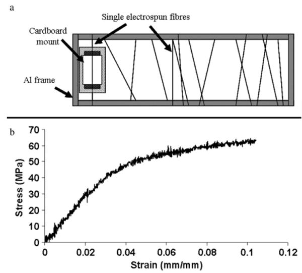
(a) Sample preparation: mounting of single nanofibre onto cardboard mount; and (b) typical stress–strain curve of a single electrospun nanofibre.
2.4. Fibre diameter determination
For each group of specimens, nanofibres were also electrospun onto a flat grounded stationary aluminium target for determination of the average fibre diameter using a scanning electron microscope (SEM). These samples were sputter-coated with ∼2.5–3 nm of chromium (Denton vacuum, DV-502A) and were observed under the SEM (Leo 1530 field emission SEM) at 1 kV. For each group of samples, the diameters of at least 80 fibres were measured prior to taking an average value.
2.5. Drug and protein distribution visualization
In order to visualize the distribution of retinoic acid in the electrospun fibres, retinoic acid-encapsulated fibre samples with a loading level of 10 wt% were used. In the case of BSA encapsulation, FITC-BSA was used to aid visualization. 0.65 wt% of FITC-BSA and 20 wt% of BSA were loaded into the polymer solution and electrospun. The drug and protein distributions throughout the nanofibres were then observed using a wide field fluorescent microscope (Nikon Eclipse TE2000-U).
2.6. X-ray diffraction
To understand the effects of solvent variation, polymer solution concentration and the addition of drugs and proteins on the structure of electrospun nanofibres, a systematic study was conducted using PCL instead of PCLEEP, because PCL is readily available in quantities required for x-ray diffraction. The electrospinning parameters used were similar to those for the preparation of the nanotensile testing samples, except for the substitution of PCLEEP with PCL. For each group of specimens, PCL nanofibres were electrospun from 1.3 ml of polymer solution. The nanofibres were then collected onto a grounded rotating (∼200 rpm) aluminium target (diameter 10 cm) in the form of random non-woven fibrous meshes (314 mm × 12 mm × 0.023 mm). X-ray diffraction spectra of the nanofibres were then obtained using a Philips X'Pert X-ray diffractometer, with 2θ ranging from 16° to 42° 2θ (Cu Kα radiation, λ = 0.1542 nm). The effect of the processing on crystal structure was quantified by fitting the region from 20° to 25° 2θ to a sum of four Voigt peak profiles plus a linear background. The peak position, amplitude, and width of each of the four peaks were allowed to vary independently, but the four peaks were constrained to have the same peak shape. Differences in crystalline perfection (i.e. the presence of defects and inhomogeneous strain) were evaluated by examining the widths of the peaks for materials prepared under different conditions, while differences in crystallographic texture were evaluated by comparing the relative intensities (areas) of the various peaks.
2.7. Polymer solution viscosity measurement
As in performing the x-ray diffraction characterization, in order to understand the effects of polymer concentration, solvent choices and drug loading levels on the viscosity of the polymer solutions, shear viscosity measurements were carried out using PCL instead of PCLEEP due to the large amount of polymer required for the rheology tests. The polymer solutions were prepared according to table 1. Shear viscosities of the polymer solutions were measured under different shear rates using a Couette viscometer (Rheometric Scientific™). All experiments were carried out at 22 ± 0.5 °C. The viscometer comprised a cup diameter of 34.0 mm and a bob diameter of 32.0 mm.
2.8. Residual solvent quantification
To ascertain that the mechanical analysis would not be affected by the presence of residual solvent in the fibre, which might bestow a plasticizing effect, the content of residual solvent in the electrospun fibres was determined by gas chromatography with a flame ionization detector using hydrogen as the carrier gas (Hewlett-Packard 5890 Series II Gas Chromatograph). The analyses were carried out according to the general analytical procedures in EPA Method 18 (40 CFR, Part 60, appendix A). PCLEEP 12%, PCLEEP64 6% electrospun at a humidity of 68–72%, H2O120 and PCL64 10% were used in this study, with the mass of the samples kept between 48.5 and 63 mg. All samples were dissolved in 2 ml of pyridine and sonicated for 30 min prior to removing 1 ml for analysis. The residual solvents quantified were dichloromethane and methanol.
2.9. Data analysis
All data are expressed as mean ± standard error of mean (SE). Statistical analyses for the mechanical properties of the samples were carried out using the Kruskal–Wallis method, followed by the Mann–Whitney U-test.
3. Results
3.1. Fibre diameter
By using different solvent mixtures and polymer concentrations to alter the solvent evaporation rate and hence the minimum possible polymer solution flow rate that could be used for each sample, the resulting average diameter of the electrospun fibres was varied between ∼230 nm and 5 μm, as shown in table 2. Figure 2 shows representative SEM images of the PCL and PCLEEP fibres, with and without drug and protein encapsulation.
Table 2.
Average diameters of single electrospun fibres.
| Sample | Fibre diameter (μm) |
|---|---|
| PCLEEP64 6% a | 0.60 ± 0.03 |
| PCLEEP64 6% b | 0.72 ± 0.01 |
| H2O120 | 0.629 ± 0.019 |
| H2O140 | 0.554 ± 0.007 |
| H2O150 | 0.496 ± 0.010 |
| PCLEEP64 8% | 1.29 ± 0.05 |
| PCLEEP 12% | 5.01 ± 0.24 |
| RA0.03 | 0.901 ± 0.017 |
| RA0.3 | 0.717 ± 0.017 |
| RA1 | 0.679 ± 0.022 |
| RA10 | 0.545 ± 0.021 |
| RA20 | 0.342 ± 0.011 |
| BSA10 | 1.123 ± 0.048 |
| BSA20 | 1.590 ± 0.112 |
| PCL64 8% | 0.228 ± 0.015 |
| PCL64 10% | 0.354 ± 0.009 |
| PCL64 12% | 0.374 ± 0.018 |
Figure 2.
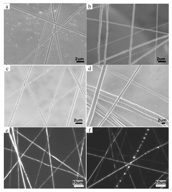
SEM micrographs of (a) plain PCLEEP fibres, PCLEEP64 6% electrospun at humidity of 68–72%; (b) plain PCL fibres, PCL64 10%; (c) retinoic acid-encapsulated (20 wt%) PCLEEP fibres; and (d) BSA-encapsulated (10 wt%) PCLEEP fibres; and wide-field fluorescent micrographs of (e) retinoic acid-encapsulated (10 wt%) PCLEEP fibres; and (f) FITC-BSA-encapsulated (20 wt%) PCLEEP fibres.
3.2. Drug and protein distribution
The distributions of retinoic acid and BSA in the PCLEEP nanofibres are shown in figures 2(e) and (f) respectively. Retinoic acid was observed to be distributed evenly and continuously throughout the nanofibres, mainly due to the fact that retinoic acid is soluble in organic solvents. In contrast, BSA was found to be distributed as aggregates due to phase separation between the polymer and protein solutions. Phase separation in the smaller nanofibres was difficult to capture due to the limited resolution of the fluorescent microscope. However, phase separation was readily apparent in the larger fibres.
3.3. Mechanical properties of nanofibres
Figure 1(b) shows a typical stress–strain curve obtained from the tensile tests. Young's modulus, tensile strength and fracture strain were then obtained from the curve according to ASTM standard D3822-01.
3.3.1. PCLEEP nanofibres
Figure 3 shows the effect of fibre diameter on the mechanical properties of single electrospun PCLEEP and PCL fibres. Both the Young's modulus, E, and tensile strength, σT, decrease with increasing fibre diameter. The fracture strain, ε, however, showed no change with fibre diameter in the submicron range, but drastically increased as the fibre diameter increased into the micron range. Similar observations were made in both PCLEEP and PCL single fibres.
Figure 3.
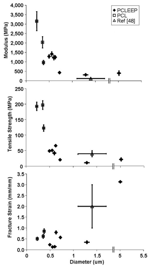
Mechanical properties of single PCLEEP and PCL electrospun fibres with respect to fibre diameter.
3.3.2. Retinoic acid-encapsulated fibres
The effect of the encapsulation of retinoic acid on the mechanical properties of the single nanofibres is shown in figure 4. Comparison was made with H2O140 and PCLEEP64 6% electrospun at 68–72% humidity due to the similar electrospinning parameters used. With increasing loading levels of retinoic acid, the fibre diameter decreased whilst E and σT increased significantly. Comparing drug-loaded fibres with plain PCLEEP fibres, no significant changes in mechanical properties were detected at low loading levels of retinoic acid. However, at higher loading levels of 10 and 20 wt%, E and σT both increased significantly. There was no discernable trend in fracture strain, ε, with drug encapsulation. However, the values did appear to lie in the lower range of the failure strains of the plain fibres as the retinoic acid loading level increased.
Figure 4.
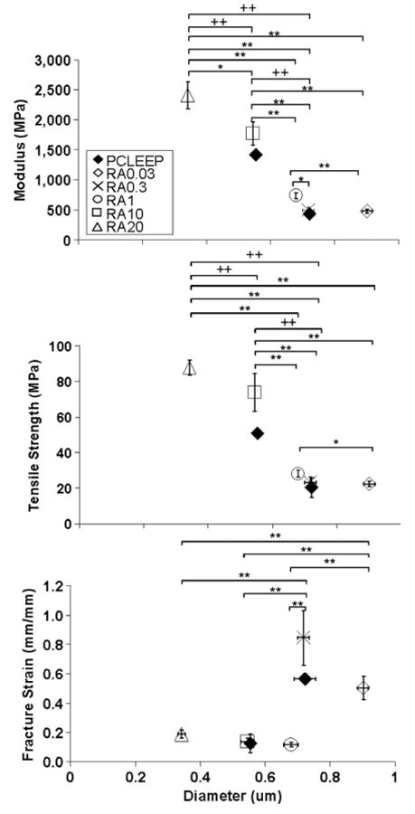
Mechanical properties of retinoic acid-encapsulated PCLEEP nanofibres with respect to fibre diameter. * p < 0.05, ** p < 0.01 for comparisons made between the mechanical properties of retinoic acid-encapsulated nanofibres; + p < 0.1, ++ p < 0.01 for comparisons made with the mechanical properties of PCLEEP plain fibres, Kruskal–Wallis and Mann–Whitney U-test.
3.3.3. BSA-encapsulated fibres
An increase in BSA loading level in PCLEEP was found to increase fibre diameter from ∼550 nm to 1.6 μm, but decreased E, σT and ε, as shown in figure 5. Comparing samples with 10 and 20 wt% loading levels of BSA with plain PCLEEP fibres electrospun with similar amounts of aqueous phase present in the polymer solution (i.e. samples H2O120 and H2O140), the presence of BSA appeared to decrease both the E and σ of the electrospun fibres significantly. Increased loading levels of BSA also appeared to decrease the ductility of the PCLEEP fibres, with the values of ε lying near the lower end of the values for plain PCLEEP fibres.
Figure 5.
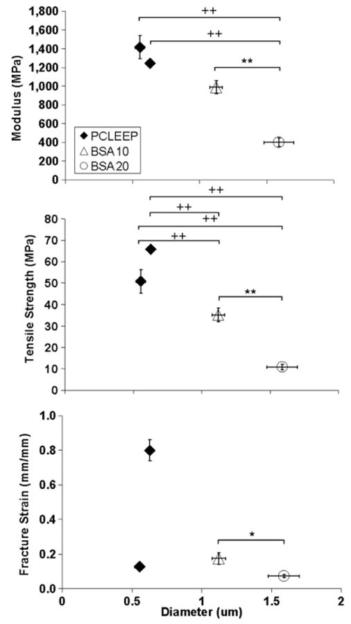
Mechanical properties of BSA-encapsulated PCLEEP fibres with respect to fibre diameter. * p < 0.05, ** p < 0.01 for comparisons made between the mechanical properties of BSA-encapsulated fibres. + p < 0.1 and ++ p < 0.01 for comparisons made with the mechanical properties of PCLEEP plain fibres. Kruskal–Wallis and Mann–Whitney U-test.
3.4. X-ray diffraction
3.4.1. Electrospinning process and polymer concentration effect
The effect of electrospinning, as compared to solvent casting, on the structure of PCL is illustrated by the x-ray diffraction patterns shown in figure 6(a). There was no discernable trend in the overall degree of crystallinity of the polymer produced by electrospinning or solvent casting. However, the larger width of the (110) peak (2θ = 21.4°) of PCL film suggested a decrease in crystalline perfection in the film as compared to electrospun fibres. A decrease in the intensity of the (111) peak (2θ = 21.9°) relative to that of the (110) peak indicates a change in crystallographic texture (i.e. preferred orientation). In particular, the relatively slower crystallization associated with solvent casting leads to some degree of (111) crystallographic texture in the XRD specimens.
Figure 6.
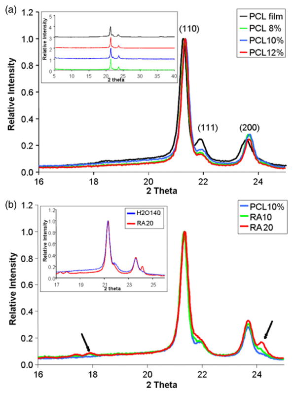
(a) Effects of electrospinning process and concentration of polymer solutions used during electrospinning on structure of PCL. XRD pattern of PCL film and electrospun nanofibrous mesh, focusing on 2θ from 16° to 25°. Inset: XRD pattern of PCL film and fibres over a wider 2θ range; and (b) XRD pattern of nanofibres composed of 10 wt% PCL with retinoic acid encapsulation. Inset: XRD pattern of PCLEEP samples, H2O140 (blue) and RA20 (red).
The effect of concentration of the polymer solution used for electrospinning on the structure of the resulting nanofibres is also shown in figure 6(a), but again there is no observable difference in the degree of crystallinity. Some slight shifting of the peaks was observed. We believe that this may be due to differences in x-ray transparency of the specimens, since each specimen was different with regard to the fraction of the total specimen area covered by fibres.
3.4.2. Solvent effect
The effect of solvent mixture on the crystallinity of the nanofibres was also analysed by comparing the x-ray diffraction patterns of H2O120 with H2O140. No observable difference was noted. Similar observations were made when a comparison was made using PCLEEP polymer, between samples PCLEEP64 6% electrospun at a humidity of 68–72% and H2O120.
3.4.3. Retinoic acid-encapsulation effect
Figure 6(b) illustrates the effect of retinoic acid encapsulation on the crystallinity of the electrospun nanofibres. The increasing amount of retinoic acid loaded into the fibres is reflected in the increase in the relative intensities of the peaks located at 2θ values of ∼18° and ∼24.2°, as indicated by the arrows. These peaks may be found in the x-ray diffraction patterns of retinoic acid (JCPDS file numbers 41-1689 and 41-1690). The sharp and well-defined crystalline peaks of retinoic acid indicate that the drug exists as discrete crystals within the nanofibres.
The addition of retinoic acid appears to have little or no effect on the degree of crystallinity of the PCL nanofibres, although changes in the relative peak intensities of PCL do indicate a change in crystallographic texture. Similar observations were made regarding the PCLEEP samples, RA20 and H2O140, as shown in the inset of figure 6(b). In the case of PCLEEP, however, an increase in the degree of crystallinity of the fibres was observed in the presence of 20 wt% of retinoic acid.
3.4.4. BSA-encapsulation effect
X-ray diffraction patterns for BSA-encapsulated nanofibres (not shown) show no systematic effect of increasing loading levels of BSA on the crystallinity or crystalline texture of the nanofibres.
3.5. Polymer solution viscosity measurement
The effects of polymer concentration and solvent variation on the viscosity of the resulting polymer solutions are shown in figures 7(a) and (b). Comparing the PCL64 samples, an increase in polymer concentration from 6 to 12 wt% raised the shear viscosity ∼7 times. On the other hand, addition of methanol (comparing PCL12% and PCL64 12%) and water (figure 7(b)) lowered the viscosity of the solutions. The presence of BSA increased the viscosity of the polymer solutions, as shown in figure 7(c); however, the addition of retinoic acid led to insignificant changes in the shear viscosity.
Figure 7.
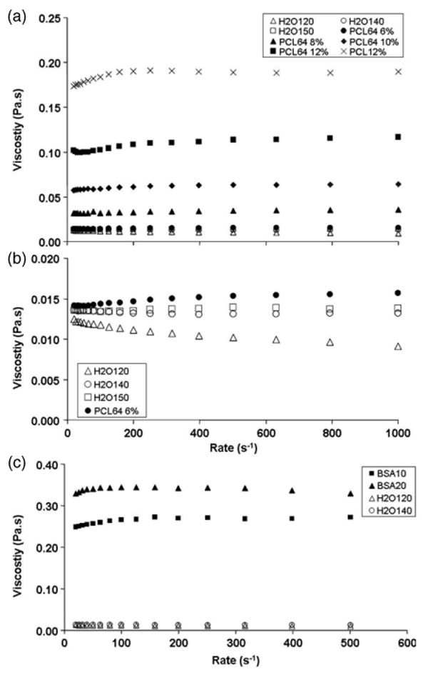
(a) Effect of polymer concentration and solvent variation on the viscosity of PCL polymer solution; (b) enlargement of viscosity versus shear rate graphs of H2O samples; and (c) effect of BSA encapsulation on the viscosity of PCL polymer solution.
3.6. Residual solvents
Neither dichloromethane nor methanol was present in any of the samples at levels above the detection limit of the gas chromatograph, as shown in table 3.
Table 3.
Residual solvent quantification of electrospun fibrous scaffolds.
| Concentration by weight (ppmw) | ||||
|---|---|---|---|---|
| Compound | PCLEEP 12% | H2O120 | PCLEEP64 6% a | PCL 10% |
| Methanol | <23.4 | <24.5 | <24.7 | <24.0 |
| Dicholormethane | <11.7 | <12.2 | <12.4 | <12.0 |
4. Discussion
4.1. Electrospinning parameters and resulting fibre diameters
The aim of this study was to understand the relationship between the diameter of biodegradable nanofibres and their mechanical properties, with or without drug encapsulation. The diameter of electrospun fibres depends on several parameters, including the concentration of the polymer solution, the rate at which the polymer solution is being dispensed during the electrospinning process, and the molecular weight of the polymer [42–44]. From previous studies and also from work carried out in our laboratory, a decrease in polymer solution dispense rate decreases the diameter of the electrospun fibres [42, 43]. Therefore, in order to obtain nanosized fibres, focus was placed on changing the polymer solution dispense rate through the use of different solvents. Mixtures of solvents were used in order to vary and decrease the solvent evaporation rate, so as to allow low solution flow rates to be used during electrospinning. This prevents the polymer solution from drying and clogging the electrospinning needle prior to being pulled into nanofibres. The basic solvent used in this study was dichloromethane, whilst methanol and water were added to decrease the evaporation rate of the final mixture. Only dichloromethane was used for electrospinning BSA since methanol precipitates BSA.
A systematic study was carried out in order to determine the concentration of polymer required for a specific polymer–solvent combination, so as to ensure the absence of beads in the final product. The concentrations shown in table 1 for each polymer–solvent combination are the lowest concentrations that can be used without the formation of beads in the nanofibres.
The changes in solvent mixture and polymer concentration not only altered the solution evaporation rate, but also inevitably affected other properties of the polymer solutions such as viscosity. In general, the decrease in fibre diameter (table 2) corresponded with the decrease in shear viscosity (figure 7). This observation is consistent with literature [45]. However, in the case of the H2O samples, the decreasing trend in solution viscosity with the addition of water did not directly correlate with a similar trend in fibre diameter variation. This implies that the fibre diameter is not solely dependent on polymer solution viscosity. The initial decrease in fibre diameters for H2O140 and H2O150 as compared to the same concentration of polymer solution without addition of water is likely due to the lower viscosities of the polymer solutions. However, in the presence of a larger amount of water for the H2O120 sample, the viscosity effect appeared to play a less important role. In this case, increased jet stability during electrospinning may have resulted in the increase in fibre diameter. This stability, imparted by the lower solvent evaporation rate of water, resulted in a lower degree of jet thinning. Altogether, the control of fibre diameter during electrospinning is a complicated process and involves several interdependent parameters like solution viscosity, solvent evaporation rate and polymer solution flow rate.
4.2. Fibre diameter determination
Analysis of the fibre morphology and diameter under the SEM revealed a distribution of sizes, which is common for electrospun fibres. Ideally, measurements of the mechanical properties of each single nanofibre should be conducted with the exact dimensions of the particular nanofibre known, instead of using the mean diameter of the population for computation. However, the use of the mean diameter of each group of samples was still adopted, for several reasons. Most importantly, at the nanoscale, accurate measurement of the dimension of the fibres requires measurement in a scanning electron microscope. However, preparation of samples for SEM requires metal coating that would render them unsuitable for subsequent mechanical testing. Also, it is difficult to determine the size of a single fibre just prior to the mechanical tests due to the ease of sample breakage during the measurement process. Lastly, it is also difficult to obtain separate mechanical testing samples with the exact same fibre diameter. To permit statistical comparison, performing the analysis on a group of fibres within a range of diameters is the best option.
Although the data make it appear that the diameters of a population of fibres were measured, in reality, this ‘population’ of fibres is actually a single long fibre deposited in a random manner on the grounded target since a continuous supply of polymer solution was used during the electrospinning process. The measurement of the diameters, therefore, is a measure of the fibre diameter along various segments of one continuous fibre. Similarly, the mechanical testing was carried out on various parts of one fibre.
4.3. Mechanical properties of PCLEEP and PCL
With the aim of understanding the effect of size on the mechanical properties of the nanofibres, groups of fibres with different diameters were obtained by using different mixtures of solvents and different polymer concentrations. Solvents and polymer concentration affect the rate of solidification and crystallization of a polymer. This may change the degree of crystallinity and crystalline fibre texture of the polymer and hence its mechanical properties. As such, an attempt to separate the effects of degree of crystallinity and crystallographic texture from the effect of size was made by carrying out x-ray diffraction analyses. Since a systematic study using the x-ray diffraction test requires a relatively large specimen volume, the study was carried out using PCL because this polymer is commercially available in large quantities.
As shown in figure 6(a), electrospinning does not measurably affect the degree of crystallinity (i.e. the volume fraction of the crystalline phase) as compared to solvent casting. However, a decrease in the relative intensity of the (111) peak at 2θ = 21.9° and a decrease in the width of the (110) peak at 2θ = 21.4° for the electrospun fibres were also observed. This is indicative of a difference in crystallographic texture and an increase in crystalline perfection in the electrospun fibres respectively. The (111) peak for the PCL film is more intense than that of a random polycrystalline PCL sample (calculated using the program GSAS from the crystal structure of PCL) [46, 47]. This indicates a preferential alignment of the crystals in the solvent-cast specimen, with the (111) planes parallel to the XRD specimen surface. In contrast, the intensity of the (111) peak from the electrospun fibres is closer to that expected for a random polycrystal. This is interesting, given that electrospinning is a highly asymmetric process, with the polymer jet stretching and elongating up to several orders of magnitude along the longitudinal axis of the fibre. One might reasonably expect such a situation to lead to a pronounced crystallographic texture, which should be observable in the XRD patterns since the fibre axes are mostly parallel to the sample surface in these experiments. With the fibre axes lying in the plane, diffraction from the corresponding crystallographic plane would therefore be quite weak. However, the fact that we observe XRD patterns from the fibres comparable to that expected for random polycrystals suggests that this is not correct and that there is no strong crystallographic texture.
Comparing the mechanical properties of PCLEEP with that of PCL obtained from this study and the study by Tan et al [48], the mechanical properties of PCLEEP nanofibres appear to be comparable to that of PCL. The effect of fibre diameter on the mechanical properties of PCLEEP observed in this study was similar to the observations made by Tan et al [49], in that E for single nanofibres increases as the fibre diameter decreases into the nanometre range. However, as fibre diameter increases, the properties of the single fibre approach that of the bulk. The trend of mechanical enhancement with decreased size may also be observed by comparing the mechanical properties of PCL nanofibres with PCL sheets (Mw 86 000–89 000) (PCL sheet properties: E ∼ 330–570 MPa [50, 51]; σ ∼ 10–15 MPa [50, 52]; ε ∼ 0.4–1.2 mm mm−1 [50, 52]). The modulus of single PCL nanofibres was at least twice as high as that of bulk PCL, while the strength was an order of magnitude higher. While a clear relationship between size and mechanical properties was observed, the actual mechanism behind the observed size effect in the electrospun fibres remains to be elucidated. One possibility is that the enhancement of the mechanical properties may be due to a difference in the crystalline microstructure of the fibres as compared to the film. However, on the basis of the x-ray diffraction results, the difference in the degree of crystallinity appears to be small, and while there is an observable difference in crystallographic texture and crystalline perfection, it is not clear that this difference can explain the very large differences in mechanical properties. The structural observations made on the electrospun fibres are also not conclusive. Despite the differences in electrospinning parameters (polymer solution concentration and the combination of solvents used), x-ray diffraction revealed no significant changes in the degree of crystallinity, crystalline perfection, or texture in the nanofibres. This may either imply that the differences in the mechanical properties of the nanofibres are not due to crystallinity differences, or it may suggest the lack of sensitivity and resolution of the experimental approach in picking up the subtle differences in molecular structure. Therefore, measurements at the molecular level, such as atomic force microscopy, may be needed to elucidate the mechanism behind the observed size effect.
Following the observations made on the Young's modulus and tensile strength of the nanofibres, one would expect the elongation at fracture to observe a size effect as well. However, the value appeared to be unaffected by the diameter of the polymer fibres. A possible reasoning is the difference in mechanism by which failure occurs during plastic deformation, such as multiple necking occurring on the nanofibres instead of a single necking along the bulk polymeric material. A confirmation of such a hypothesis would require an in situ observation of the failure mechanism during the tensile test.
4.4. Effects of retinoic acid encapsulation
Combining results from figures 3 and 4, the presence of retinoic acid increased the strength and stiffness of the nanofibres, independent of processing parameters and the diameter of the nanofibres. The enhanced mechanical properties of the nanofibres may be a result of the presence of retinoic acid nanocrystals (figure 6(b)). The retinoic acid and PCLEEP may act as a composite system, with nanocrystals of retinoic acid reinforcing and restricting the movement of the polymer chains as the polymer elongates under tensile force. Consistent with this view, the elasticity would decrease, and indeed the elongation-to-break values of the drug-encapsulated nanofibres lie on the lower range of the ε values of the plain PCLEEP fibres. This observed enhancement in mechanical properties by retinoic acid nanocrystals is also similar to the observations made by Wutticharoenmongkol et al [53], whereby the mechanical properties of PCL electrospun fibrous scaffolds were enhanced by the incorporation of calcium carbonate or hydroxyapatite nanoparticles as compared to corresponding film substrates.
Comparing amongst the retinoic acid-encapsulated fibres, a size effect may also be an additional contributing factor to the increase in mechanical properties with increasing drug loading level, since a concomitant decrease in fibre diameter was observed. The addition of retinoic acid resulted in a decrease in fibre diameter, with all other electrospinning parameters kept constant. This may be due to the change in the charge density of the polymer solution, resulting in a more unstable jet being formed with increasing amounts of retinoic acid. The increased jet instability results in increased fibre spinning and elongation, which ultimately leads to the reduction in fibre diameter.
4.5. Effects of BSA encapsulation
Under the electrospinning parameters used in this study, 10 wt% of BSA was found to be the minimum weight percentage that could be electrospun from 8 wt% of PCLEEP in dichloromethane, without bead formation. The encapsulation of a smaller amount of BSA required a higher concentration of PCLEEP solution, and hence was not used, in order to minimize processing variations during electrospinning, which could in turn contribute to differences in the mechanical properties of the resulting fibres. It was also difficult to electrospin solutions containing more than 20 wt% of BSA due to the presence of a large amount of aqueous suspension in the polymer solution, thereby resulting in frequent jet breakage during the electrospinning process.
The addition of BSA resulted in an increase in fibre diameter, compared to adding a similar volume of blank buffer to the PCLEEP solution during the electrospinning process. This may be due to the increase in viscosity of the polymer solution and also the presence of a significant amount of protein molecules, soluble or aggregated, within the polymeric fibre.
Combining the results from figures 3 and 5, BSA encapsulation resulted in weaker and more brittle fibres, independent of the effects of size and processing parameters. This may be due to the observed phase separation between BSA and the polymer (figure 2(f)), resulting in the restriction in polymer chain movement and elongation at the interface of these two regions during tensile deformation. The effects of BSA encapsulation on the Young's modulus and tensile strength of the electrospun fibres, however, is less conclusive. Analysis focusing on micron-sized plain PCLEEP fibres of dimensions similar to the BSA-encapsulated fibres will be required instead in order to separate the effects of size from protein encapsulation. Nonetheless, consistent with our other results, the increase in fibre diameter due to BSA incorporation results in a decrease in both strength and stiffness of the nanofibres. As discussed above, the x-ray diffraction analysis showed no significant effect of BSA on the crystalline structure of the fibres.
4.6. Residual solvent quantification
There has been no information in the field regarding the residual solvent content in electrospun fibres. The negligible level determined in this study indicates that, at least for low boiling solvents such as dichloromethane and methanol, there is no need to worry about the plasticizing effect of these solvents on the mechanical properties. This finding also suggests that fibres electrospun from these solvents would bode well in biocompatibility consideration.
5. Conclusions
The mechanical properties, namely the Young's modulus and tensile strength, of PCLEEP and PCL nanofibres increase dramatically as the diameter of the fibres decreases from bulk (∼5 μm) down to the nanometre regime (200–300 nm). There is no significant difference in the degree of crystallinity between the PCL film and PCL nanofibres, although the films do have some (111) crystallographic texture and a lower degree of crystalline perfection that may influence the mechanical properties. The inclusion of drugs and proteins in the electrospun fibres significantly alters the mechanical properties of the fibres. The addition of retinoic acid enhances the mechanical properties, while the presence of BSA produces the opposite effect. Interestingly, the x-ray diffraction analysis appears to show no strong effect of diameter on the crystalline structure of the electrospun fibres. The understanding of the effects of size and drug and protein encapsulation on the mechanical properties of the electrospun fibres may help in the optimization of tissue scaffold design that incorporates biochemical and mechanical cues for tissue regeneration.
Acknowledgments
SYC would like to thank Ms Eunice P S Tan of the National University of Singapore for her demonstration of the use of the nanotensile tester, and is grateful for the support of a Nanyang Technological University Overseas Scholarship. Support of this work by NIH (EB003447) is also acknowledged.
References
- 1.Ma PX, Zhang R. Synthetic nano-scale fibrous extracellular matrix. J Biomed Mater Res. 1999;46:60–72. doi: 10.1002/(sici)1097-4636(199907)46:1<60::aid-jbm7>3.0.co;2-h. [DOI] [PubMed] [Google Scholar]
- 2.Hartgerink JD, Beniash E, Stupp SI. Peptide-amphiphile nanofibers: a versatile scaffold for the preparation of self assembling materials. Proc Natl Acad Sci USA. 2002;99:5133–8. doi: 10.1073/pnas.072699999. [DOI] [PMC free article] [PubMed] [Google Scholar]
- 3.Stitzel JD, Pawlowski KJ, Wnek GE, Simpson DG, Bowlin GL. Arterial smooth muscle cell proliferation on a novel biomimicking, biodegradable vascular graft scaffold. J Biomater Appl. 2001;16:22–33. doi: 10.1106/U2UU-M9QH-Y0BB-5GYL. [DOI] [PubMed] [Google Scholar]
- 4.Yim EKF, Leong KW. Significance of synthetic nanostructures in dictating cellular response. Nanomed Nanotechnol Biol Med. 2005;1:10–21. doi: 10.1016/j.nano.2004.11.008. [DOI] [PubMed] [Google Scholar]
- 5.Jiang H, Fang D, Hsiao D, Chu B, Chen W. Preparation and characterization of ibuprofen-loaded poly(lactide-co-glycolide)/poly(ethylene glycol)-g-chitosan electrospun membranes. J Biomater Sci Polym Edn. 2004;15:279–96. doi: 10.1163/156856204322977184. [DOI] [PubMed] [Google Scholar]
- 6.Katti DS, Robinson KW, Ko FK, Laurencin CT. Bioresorbable nanofiber-based systems for wound healing and drug delivery: optimization of fabrication parameters. J Biomed Mater Res B. 2004;70:286–96. doi: 10.1002/jbm.b.30041. [DOI] [PubMed] [Google Scholar]
- 7.Zeng J, Xu X, Chen X, Liang Q, Bian X, Yang L, Jing X. Biodegradable electrospun fibers for drug delivery. J Controll Release. 2003;92:227–31. doi: 10.1016/s0168-3659(03)00372-9. [DOI] [PubMed] [Google Scholar]
- 8.Kenawy ER, Bowlin GL, Mansfield K, Layman J, Simpson DG, Sanders EH, Wnek GE. Release of tetracycline hydrochloride from electrospun poly(ethylene-co-vinylacetate, poly(lactic acid), and a blend. J Control Release. 2002;81:57–64. doi: 10.1016/s0168-3659(02)00041-x. [DOI] [PubMed] [Google Scholar]
- 9.Chew SY, Wen J, Yim EKF, Leong KW. Sustained release of proteins from electrospun biodegradable fibers. Biomacromolecules. 2005;6:2017–24. doi: 10.1021/bm0501149. [DOI] [PubMed] [Google Scholar]
- 10.Flanagan LA, Ju YE, Marg B, Osterfield M, Janmey PA. Neurite branching on deformable substrates. NeuroReport. 2002;13:2411–5. doi: 10.1097/01.wnr.0000048003.96487.97. [DOI] [PMC free article] [PubMed] [Google Scholar]
- 11.Huang S, Ingber DE. The structural and mechanical complexity of cell-growth control. Nat Cell Biol. 1999;1:E131–8. doi: 10.1038/13043. [DOI] [PubMed] [Google Scholar]
- 12.Ingber DE. Mechanobiology and diseases of mechanotransduction. Ann Med. 2003;35:564–77. doi: 10.1080/07853890310016333. [DOI] [PubMed] [Google Scholar]
- 13.Polte TR, Eichler GS, Wang N, Ingber DE. Extracellular matrix controls myosin light chain phosphorylation and cell contractility through modulation of cell shape and cytoskeletal prestress. Am J Physiol Cell Physiol. 2004;286:C518–28. doi: 10.1152/ajpcell.00280.2003. [DOI] [PubMed] [Google Scholar]
- 14.Ingber DE. Mechanical signalling. Ann NY Acad Sci. 2002;961:162–3. doi: 10.1111/j.1749-6632.2002.tb03074.x. [DOI] [PubMed] [Google Scholar]
- 15.Ingber DE. Mechanosensation through integrins: cells act locally but think globally. Proc Natl Acad Sci USA. 2003;100:1472–4. doi: 10.1073/pnas.0530201100. [DOI] [PMC free article] [PubMed] [Google Scholar]
- 16.Ingber DE, Folkman J. Mechanochemical switching between growth and differentiation during fibroblast growth factor-stimulated angiogenesis in vitro: role of extracellular matrix. J Cell Biol. 1989;109:317–30. doi: 10.1083/jcb.109.1.317. [DOI] [PMC free article] [PubMed] [Google Scholar]
- 17.Ingber DE. In: Principles of Tissue Engineering. Lanza R, Langer R, Chick W, editors. Austin TX: R G Landes Co.; 1997. pp. 89–100. [Google Scholar]
- 18.Wang HB, Dembo H, Wang YL. Substrate flexibility regulates growth and apoptosis of normal but not transformed cells. Am J Physiol Cell Physiol. 2000;279:C1345–50. doi: 10.1152/ajpcell.2000.279.5.C1345. [DOI] [PubMed] [Google Scholar]
- 19.Genes NG, Rowley JA, Mooney DJ, Bonassar LJ. Effect of substrate mechanics on chondrocyte adhesion to modified alginate surfaces. Arch Biochem Biophys. 2004;422:161–7. doi: 10.1016/j.abb.2003.11.023. [DOI] [PubMed] [Google Scholar]
- 20.Thompson MT, Berg MC, Tobias IS, Rubner MF, Vliet KJV. Tuning compliance of nanoscale polyelectrolyte multilayers to modulate cell adhesion. Biomaterials. 2005;26:6836–45. doi: 10.1016/j.biomaterials.2005.05.003. [DOI] [PubMed] [Google Scholar]
- 21.Kong HJ, Liu J, Riddle K, Matsumoto T, Leach K, Mooney DJ. Non-viral gene delivery regulated by stiffness of cell adhesion substrates. Nat Mater. 2005;4:460–4. doi: 10.1038/nmat1392. [DOI] [PubMed] [Google Scholar]
- 22.Yeung T, et al. Effects of substrate stiffness on cell morphology, cytoskeletal structure, and adhesion. Cell Motility Cytoskeleton. 2005;60:24–34. doi: 10.1002/cm.20041. [DOI] [PubMed] [Google Scholar]
- 23.Brown XQ, Ookawa K, Wong JY. Evaluation of polydimethylsiloxane scaffolds with physiologically-relevant elastic moduli: interplay of substrate mechanics and surface chemistry effects on vascular smooth muscle cell response. Biomaterials. 2005;26:3123–9. doi: 10.1016/j.biomaterials.2004.08.009. [DOI] [PubMed] [Google Scholar]
- 24.Ingber DE. Mechanical control of tissue growth: Function follows form. Proc Natl Acad Sci USA. 2005;102:11471–572. doi: 10.1073/pnas.0505939102. [DOI] [PMC free article] [PubMed] [Google Scholar]
- 25.Fujihara K, Kotaki M, Ramakrishna S. Guided bone regeneration membrane made of polycaprolactone/calcium carbonate composite nano-fibers. Biomaterials. 2005;26:4139–47. doi: 10.1016/j.biomaterials.2004.09.014. [DOI] [PubMed] [Google Scholar]
- 26.Riboldi SA, Sampaolesi M, Neuenschwander P, Cossu G, Mantero S. Electrospun degradable polyesterurethane membranes: potential scaffolds for skeletal muscle tissue engineering. Biomaterials. 2005;26:4606–15. doi: 10.1016/j.biomaterials.2004.11.035. [DOI] [PubMed] [Google Scholar]
- 27.Kwon IK, Kidoaki S, Matsuda T. Electrospun nano-to microfiber fabrics made of biodegradable copolyesters: structural characteristics, mechanical properties and cell adhesion potential. Biomaterials. 2005;26:3929–39. doi: 10.1016/j.biomaterials.2004.10.007. [DOI] [PubMed] [Google Scholar]
- 28.Li WJ, Laurencin CT, Caterson EJ, Tuan RS, Ko FK. Electrospun nanofibrous structure: a novel scaffold for tissue engineering. J Biomed Mater Res. 2002;60:613–21. doi: 10.1002/jbm.10167. [DOI] [PubMed] [Google Scholar]
- 29.Xu C, Inai R, Kotaki M, Ramakrishna S. Electrospun nanofiber fabrication as synthetic extracellular matrix and its potential for vascular tissue engineering. Tissue Eng. 2004;10:1160–8. doi: 10.1089/ten.2004.10.1160. [DOI] [PubMed] [Google Scholar]
- 30.Jin HJ, Chen J, Karageorgiou V, Altman GH, Kaplan DL. Human bone marrow stromal cell responses to electrospun silk fibroin mats. Biomaterials. 2004;25:1039–47. doi: 10.1016/s0142-9612(03)00609-4. [DOI] [PubMed] [Google Scholar]
- 31.Luu YK, Kim K, Hsiao BS, Chu B, Hadjiargyrou M. Development of a nanostructured DNA delivery scaffold via electrospinning of PLGA and PLA-PEG block copolymers. J Control Release. 2003;89:341–53. doi: 10.1016/s0168-3659(03)00097-x. [DOI] [PubMed] [Google Scholar]
- 32.Ayutsede J, Gandhi M, Sukigara S, Micklus M, Chen HE, Ko F. Regeneration of Bombyx mori silk by electrospinning. Part 3: characterization of electrospun nonwoven mat. Polymer. 2005;46:1625–34. [Google Scholar]
- 33.Bhattarai N, Cha DI, Bhattarai SR, Khil MS, Kim HY. Biodegradable electrospun mat: novel block copolymer of poly(p-dioxanone-co-L-lactide)-block-poly (ethylene glycol) J Polym Sci B. 2003;41:1955–64. [Google Scholar]
- 34.He W, Ma Z, Yong T, Teo WE, Ramakrishna S. Fabrication of collagen-coated biodegradable polymer nanofiber mesh and its potential for endothelial cells growth. Biomaterials. 2005;26:7606–15. doi: 10.1016/j.biomaterials.2005.05.049. [DOI] [PubMed] [Google Scholar]
- 35.Shields KJ, Beckman MJ, Bowlin GL, Wayne JS. Mechanical properties and cellular proliferation of electrospun collagen type II. Tissue Eng. 2004;10:1510–7. doi: 10.1089/ten.2004.10.1510. [DOI] [PubMed] [Google Scholar]
- 36.Courtney T, Sacks MS, Stankus J, Guan J, Wagner WR. Design and analysis of tissue engineering scaffolds that mimic soft tissue mechanical anisotropy. Biomaterials. 2006;27:3631–8. doi: 10.1016/j.biomaterials.2006.02.024. [DOI] [PubMed] [Google Scholar]
- 37.Inai R, Kotaki M, Ramakrishna S. Structure and properties of electrospun PLLA single nanofibres. Nanotechnology. 2005;16:208–13. doi: 10.1088/0957-4484/16/2/005. [DOI] [PubMed] [Google Scholar]
- 38.Tan EPS, Lim CT. Mechanical characterization of nanofibers—a review. Compos Sci Technol. 2006;66:1102. [Google Scholar]
- 39.Tan EPS, Goh CN, Sow CH, Lim CT. Tensile test of a single polymer nanofiber using an AFM tip. Appl Phys Lett. 2005;86:073115. [Google Scholar]
- 40.Lim EPS, Lim CT. Characterization of bulk properties of polymer nanofibrous scaffolds from nanomechanical properties of single nanofibers. J Biomed Mater Res A. 2006;77:526. doi: 10.1002/jbm.a.30646. [DOI] [PubMed] [Google Scholar]
- 41.Wen J, Zhuo RX. Preparation and characterization of poly(D,L-lactide-coethylene methyl phosphate) Polym Int. 1998;47:503–9. [Google Scholar]
- 42.Zong XH, Kim K, Fang DF, Ran SF, Hsiao BS, Chu B. Structure and process relationship of electrospun bioabsorbable nanofiber membranes. Polymer. 2002;43:4403–12. [Google Scholar]
- 43.Fridrikh SV, Yu JH, Brenner MP, Rutledge GC. Controlling the fiber diameter during electrospinning. Phys Rev Lett. 2003;90:144502. doi: 10.1103/PhysRevLett.90.144502. [DOI] [PubMed] [Google Scholar]
- 44.Matthews JA, Wnek GE, Simpson DG, Bowlin GL. Electrospinning of collagen nanofibers. Biomacromolecules. 2002;3:232–8. doi: 10.1021/bm015533u. [DOI] [PubMed] [Google Scholar]
- 45.Deitzel JM, Kleinmeyer J, Harris D, Tan NCB. The effect of processing variables on the morphology of electrospun nanofibers and textiles. Polymer. 2001;42:261–72. [Google Scholar]
- 46.Larson AC, Dreele RBV. General Structure Analysis System (GSAS) Los Alamos National Laboratory Report LAUR 86 2000 [Google Scholar]
- 47.Bittiger H, Marchessault RH. Crystal structure of Poly-ε-caprolactone. Acta Crystallogr B. 1970;26:1923–7. [Google Scholar]
- 48.Tan EPS, Ng SY, Lim CT. Tensile testing of a single ultrafine polymeric fiber. Biomaterials. 2004;26:1453–6. doi: 10.1016/j.biomaterials.2004.05.021. [DOI] [PubMed] [Google Scholar]
- 49.Tan EPS, Lim CT. Physical properties of a single polymeric nanofiber. Appl Phys Lett. 2004;84:1603–5. [Google Scholar]
- 50.Calandrelli L, Immirzi B, Malinconico M. Natural and synthetic hydroxyapatite filled PCL: mechanical properties and biocompatibility analysis. J Bioact Compat Polym. 2004;19:301–13. [Google Scholar]
- 51.Corden TJ, Jones IA, Rudd CD, Christian P, Downes S, McDougall KE. Physical and biocompatibility properties of poly-e-caprolactone produced using in situ polymerisation: a novel manufacturing technique for long-‘bre composite materials’. Biomaterials. 2000;21:713–24. doi: 10.1016/s0142-9612(99)00236-7. [DOI] [PubMed] [Google Scholar]
- 52.Sarasam A, Madihally SV. Characterization of chitosan–polycaprolactone blends for tissue engineering applications. Biomaterials. 2005;26:5500–8. doi: 10.1016/j.biomaterials.2005.01.071. [DOI] [PubMed] [Google Scholar]
- 53.Wutticharoenmongkol P, Sanchavanakit N, Pavasant P, Supaphol P. Novel bone scaffolds of electrospun polycaprolactone fibers filled with nanoparticles. J Nanosci Nanotechnol. 2006;6:514–22. doi: 10.1166/jnn.2006.090. [DOI] [PubMed] [Google Scholar]