Abstract
Catheter-based interventions are a form of minimally invasive surgery that can decrease hospitalization time and greatly lower patient morbidity compared to traditional methods. However, percutaneous catheter procedures are hindered by a lack of precise tip manipulation when actuation forces are transmitted over the length of the catheter. Active catheters with local shape-memory-alloy (SMA) actuation can potentially provide the desired manipulation of a catheter tip, but hysteresis makes it difficult to control the actuators. A method to integrate small-volume, compliant sensors on an active catheter to provide position feedback for control would greatly improve the viability of SMA-based active catheters. In this work, we describe the design, fabrication, and performance of resistance-based position sensors that are laser-machined from superelastic SMA tubing. Combining simple material models and rapid prototyping, we can develop sensors of appropriate stiffness and sensitivity with simple modifications in sensor geometry. The sensors exhibit excellent linearity over the operating range and are designed to be easily integrated onto an active catheter substrate.
Index Terms: position sensing, feedback, shape memory alloy, minimally invasive, active catheters
I. INTRODUCTION
Surgery is moving toward minimally invasive methods that lower patient morbidity, decrease recovery times, and lower hospitalization costs. Although catheter-based interventions are becoming increasingly popular in intracardiac procedures, existing manual catheters lack the precision and dexterity needed to reach the desired locations inside the heart efficiently and effectively; this can lead to long operating times averaging 4 to 5 hours [1]. In arrhythmia ablation procedures, success rates rely on the ability to create contiguous lesions, requiring precise manipulation of the catheter tip to within 3–4 mm [2]. In most cases, the surgeon must manipulate the tip by pulling cables along the catheter’s 100 cm length from outside the body. Force translation is impaired by friction and stiction along the catheter between the physician’s hand and the catheter tip. Therefore, existing catheters cannot match the manipulative capability or proprioceptive feedback that is available during more invasive open chest procedures.
Development of a robotic or “active” catheter that can provide local, precise actuation relative to the tip of the catheter can potentially overcome these challenges. Additional sensory information is necessary for precise control and force feedback, however.
Shape memory alloy (SMA) actuators have the large force to volume ratio that make them an ideal candidate for minimally invasive tools [3]–[5]. Unfortunately, the actuators also exhibit a large hysteresis, which makes them difficult to control. Model-based open-loop control as well as feedback control using the SMA actuator’s own electrical resistance have not led to reliable and controllable actuators [6]–[8].
Adding separate position sensors can provide position feedback for precise control of SMA actuators [9], [10]. We have previously developed SMA actuators laser-machined from nitinol tubing that exhibit up to 2 N of force at 20% elongation. If good position sensing is provided, the actuators can be controlled precisely regardless of their material properties [11]–[13].
Many position sensing techniques exist, but few are easily integrated into a catheter form, due to size, geometry, and flexibility constraints. Fiber optic strain sensors fit the desired form, but they can be challenging to integrate into more complex devices such as graspers. Wu and Nahm have indicated that nitinol itself can be used for sensing purposes [14], [15], but a simple method for producing small-volume and compliant SMA sensors has not been demonstrated.
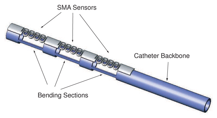
We have developed a method for designing resistance-based SMA sensors that can provide precise position information over a large displacement and enable feedback control of nonlinear SMA actuators for active catheters. This fabrication process derives directly from previous work in designing SMA actuators [11], [13]. By laser-machining nitinol tubing, we can develop winding sensors that have sufficient compliance, displacement, and signal output to be integrated effectively onto an active catheter, as shown in Figure 1. Using a simple finite element analysis (FEA) model and experimental verification, we can quickly develop customized sensors that can be readily integrated onto a catheter or more complex modular devices requiring compliant position sensing.
Fig. 1.
Concept of SMA sensors mounted on SMA backbone used as an active catheter.
In this paper, we describe the design, fabrication, and experimental testing of the sensors. We show that by combining simplified material modeling and rapid prototyping, we can alter the dimensions of the sensors to achieve the desired criteria despite variations in the manufacturing process and complex material characteristics. Although many geometries are possible, we focus the work on variations of a specific geometry to highlight the capabilities of the design process. The final sensor design achieves excellent linearity and sufficient signal output to be useful for an active catheter.
II. SHAPE MEMORY ALLOYS
Shape memory alloys (SMAs), especially nickel-titanium (or nitinol), have become increasingly popular in many applications of robotics and medical devices [16], [17]. They are primarily used in two modes of operation - as actuators and as passive, compliant elements. As actuators, they perform well in miniaturized applications because of their large power density. In addition, many passive devices take advantage of the material’s superelastic properties.
Shape memory alloys undergo a solid phase transition between the stiff austenite phase and the more compliant martensite phase, induced by stress and temperature. After being plastically deformed in its low temperature martensite phase, the SMA material can recover strains up to 8% when heated to austenite [18]. This is known as the shape memory effect and is used in temperature-dependent actuators. Additionally, a superelastic effect can be induced if the material is strained when its temperature is above its austenite finish temperature, Af. In this mode, the material behaves elastically up to the yield stress, after which martensite crystals form and large material strains are achievable with little increased stress. In this paper, we focus on the development of SMA sensors from material exhibiting the superelastic effect.
III. INITIAL CHARACTERIZATIONS OF SMA TUBING
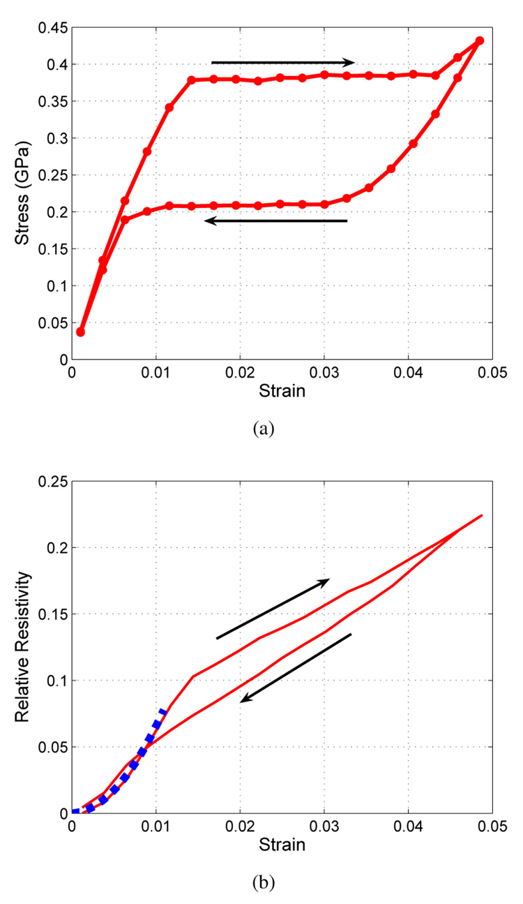
Figure 2a shows the stress-strain relationship of an 11.4 mm long, 127 µm wide strip cut from nitinol tubing. The typical flag-shaped hysteresis is indicative of a superelastic response. We have previously shown that both nitinol wires and strips of nitinol tubing exhibit a non-hysteretic quadratic resistivity with axial strain [19]. Beyond the yield stress, this resistivity increases linearly but has hysteresis. Figure 2b shows the relative resistivity vs. strain with quadratic and linear regions. The resistivity can increase up to 8.3 % before reaching the yield strain at approximately 1.2 % when axially strained.
Fig. 2.
(a) Superelastic stress-strain curve of a strip cut from nitinol tubing. (b) Relative resistivity vs. strain, showing quadratic and linear regions. The dashed line shows the quadratic fit used for FEA simulations.
If stresses in the material are kept below the yield stress, the resistivity of the SMA can be approximated as a quadratic equation with strain. Therefore, an effective sensor should have material strains less than 1.2 %. The dashed line in Fig. 2 shows an experimental fit to the axial strain data below this yield strain. By developing sensor geometries in which the material strain is confined to this non-hysteretic region of operation, we can use a simple quadratic model for the resistivity to compare finite element analysis (FEA) designs of more complex structures.
For standard strain gauges, the gauge factor (GF) is defined as
| (1) |
where ΔR/R is the relative change in resistance, and ε is the strain. Typical metal foil strain gauges have gauge factors of about 2.0 [20]. Given resistance measurements of the tube strip, this SMA superelastic tubing has a gauge factor of 6.9 in axial strain.
IV. DESIGN APPROACH
A number of researchers have developed numerical models for simulating the properties of nitinol, but these models often require experimentally determined constants or are limited to specific geometries [7], [18], [21], [22]. In contrast, our rapid prototyping method uses a simplified FEA model based on easily obtained material parameters for quick comparison of the relative performance of the sensors when certain dimensions are varied. Experimental verification is then used to measure the sensors’ true performance, which informs the next cycle of design. This approach allows us to rapidly prototype different SMA sensor designs and converge quickly to the desired criteria without complex material modelling.
V. SMA SENSOR DESIGN SPECIFICATIONS
There are many possible configurations of actuated segments for an active catheter. The sensor designs in this paper assume a segmented, modular active catheter with multiple bending segments, as illustrated in Fig. 1. The design process could easily be extended to other catheter or device configurations. For any configuration, however, the dimensions, stiffness, and signal output of the SMA sensor are interdependent, and all are dependent on the particular geometry chosen.
A. Design Criteria
The geometric design of the SMA sensor is constrained by a number of factors, including the capabilities of the lasermachining process, the anatomy of the human body, and integration with an SMA actuator onto an active catheter. In addition, the mechanical and electrical properties of the sensor are interdependent and reliant on the dimensions of the sensor. The main design criteria are as follows:
Size - The sensor must fit within the allowable volume while having a practically measurable absolute resistance.
Signal to Noise Ratio - The sensor must produce sufficient resistance change when stretched over the range of motion to use for feedback with relatively low noise.
Stiffness - The sensor must also be compliant so that itdoes not provide too much mechanical resistance to the actuator motion.
1) Feature Size
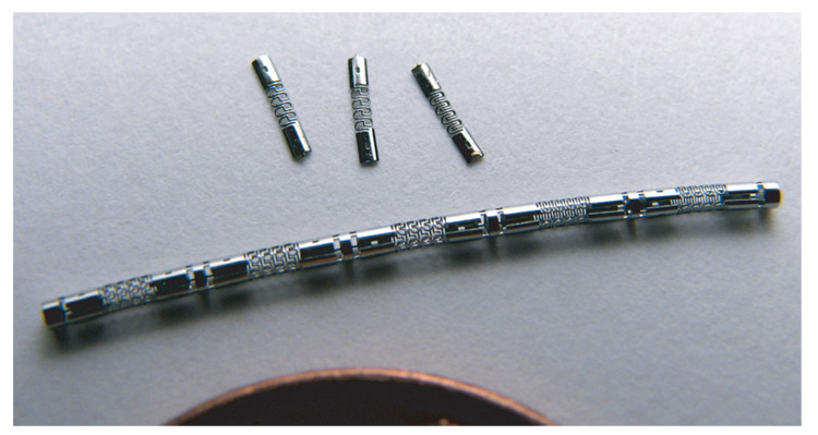
The laser-machining process can achieve feature sizes down to 25 µm (Lumenous, Inc., Sunnyvale, CA). To ensure accuracy in cutting, strut widths are kept above 40 µm. The tubing and strut thickness can also be controlled by electropolishing, which isotropically removes material and smooths the surface to improve fatigue life. Electropolishing also removes the effects of laser-heating along the cut edges although this heat affected zone (HAZ) is typically very small for this process. The sensors shown in Fig. 3 were electropolished 10 µm per side, or 20 µm total.
Fig. 3.
Photograph of sensors, both as they are cut and polished on the tubing and after being released from the tubing. The edge of an American penny is shown for scale.
2) Anatomy
For intracardiac procedures, the size of an active catheter is limited to 2–3 mm diameter in order to fit within the blood vessels. The catheter may need to travel into the left atrium of the heart, which can be approximated as an ellipsoid with a minor axis of 3–4.5 cm and a major axis of 4.5–7 cm. This restricts the bend diameter of the catheter to approximately 2.5 cm. To achieve this bend diameter with 8– 10 bending segments on the catheter, our previously developed SMA actuators are nominally 1.5 mm long and cut from 1 mm diameter tubing. They are designed to be prestretched to 300 µm elongation and to operate in the range of 150–450 µm elongation for up to 14,000 cycles.
3) Integration
The sensors in this paper are designed to operate with the actuators developed in [13], although different prestrains, dimensions, and tubing diameters could be used for other applications. In addition, the sensors should be compliant compared to the SMA actuators, which have an austenite stiffness of 1150 mN over 300 µm elongation, or roughly 3.8 mN/µm.
We have assumed that the sensor will undergo very little out-of-plane bending. Indeed, when mounted on an active catheter, the bending motion of the sensor will be constrained to a particular range, so that any effect from out-of-plane bending will simply be incorporated into the overall sensor response. The prestrain will ensure both that the sensor is in a useful operating range and that it remains in tension throughout the range of motion.
4) Tradeoffs
To achieve a measurable absolute resistance in a short overall length (1.5 mm), the sensor should be designed as a winding structure. The amount of resistance change achievable will be reduced compared to the axial strain case, because stress is not uniform over the structure. Peak stresses also must be kept below the yield stress to avoid hysteresis in the resistance response. Curved and rounded turns can aid in reducing stress concentrations, but we expect the overall change in resistance to be significantly less than in the axial case. Considering geometry constraints, we choose an absolute resistance target of 1.5 Ω or greater. This enables use of a Wheatstone bridge with sufficient output voltage to measure the resistance change without overheating the sensor with the input power.
The stiffness of the sensor also depends on the geometry and dimensions. In general for winding shapes, longer, wider, and thinner structures will tend to be less stiff. For a given tube thickness, more compliant structures have lower induced strains and hence will have lower change in resistance. Selection of thinner tubing or greater electropolishing can decrease the stiffness while increasing the resistance and signal output achievable.
Table I shows the design parameters for sensor development.
TABLE I.
Summary of Sensor Design Parameters
| Original Tube Diameter | .889 mm |
| Original Tube Wall Thickness | 102 µm |
| Electropolishing | 10 µm (20 µm total) |
| Overall Length | 1.5 mm |
| Overall Width | < .9 mm |
| Polished Strut Thickness | > 40 µm |
| Absolute Resistance | > 1.5 Ω |
| Resistance Change (ΔR) | As large as possible |
| Maximum Effective Plastic Strain | < 1 % |
| Elongation Range | 10 to 30 % |
| Stiffness | < 3.8 mN/µm |
B. Finite Element Analysis
Keeping the above criteria in mind, we developed a finite element model using three-dimensional stress-strain and dc conductivity analyses in Comsol Multiphysics (Comsol, Inc., Burlington, MA). The model uses an elastic and perfectly plastic stress-strain characteristic, with an elastic modulus of 31.5 GPa, yield stress of 380 MPa, and Poisson’s ratio of .33. Using a least-squares fit to the relative resistivity data from the strip of SMA tubing, the resistivity of the sensor is given by the following stress-dependent equation:
| (2) |
where ρ is the base resistivity (82 µΩ-cm), σ is the von Mises stress, E is the elastic modulus, and C1 and C2 are experimentally determined constants (391.3 and 0.0378, respectively) from a least-squares quadratic fit to the tube strip data.
In simulation, the sensors were each stretched to 450 µm elongation (30 %), and both the resistance and force calculated. The simulated resistance is calculated by imposing a voltage across the sensor and integrating the current flux over the end surface. The force is calculated similarly by integrating the surface traction on one end surface.
The sensor is designed to produce a non-hysteretic output, so the maximum effective plastic strain (i.e. the strain beyond the yield point) is kept below 1% at 450 µm elongation. This keeps the resistance of the bulk structure below the hysteretic region of the resistance-strain curve. Because we seek to compare relative performance of the sensors, we have ignored the curvature of the tubing in these simulations.
C. Geometry and Variations
Although many sensor designs are possible, we have focused this work on showing variations of a single design to explore the different tradeoffs when given a particular geometry.
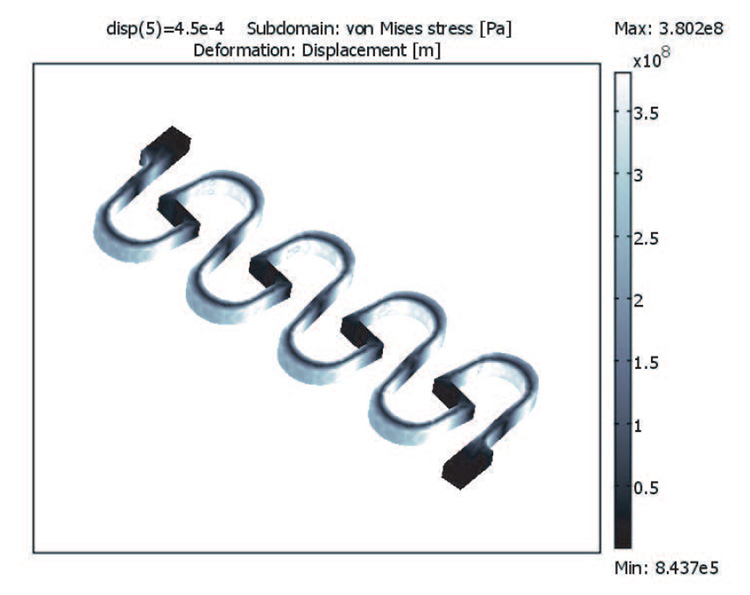
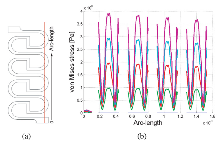
We chose a simple snaking geometry design, shown in Figure 4. The vertical strut in the middle of each turn shortens the overall length of the structure by translating the bending moment at each turn. This also increases the path length and allows for more turns in a smaller space. The curved turns reduce stress concentrations, and the off-center connections at the top and bottom reduce non-uniformity of stresses with successive turns, as shown in Figure 5. The corners of the vertical struts do not undergo significant stress and therefore need not be rounded. Figure 5b shows the stress from FEA along the line in Fig. 5a for four different elongations up to 450 µm. As can be seen in the figure, the peak stresses are roughly the same in each curve.
Fig. 4.
Example von Mises stress FEA results of a sensor design stretched to 450 µm (30 %) elongation.
Fig. 5.
(a) Geometry of sensor, showing line through which stress is calculated for the inner portions of the four right side curves. (b) von Mises stress vs. distance along the length of the line for four different displacement values.
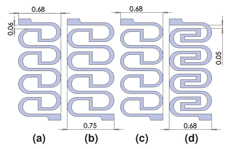
This design was also chosen for simplicity in varying its geometric parameters. Figure 6 shows four example variations. The main differences are the width of the side curves, the overall width, and the path length. As seen in the FEA simulation results in Table II, shifting these simple parameters can affect the absolute resistance, percent resistance change, and stiffness (estimated as the force at 450 µm elongation divided by 450 µm).
Fig. 6.
Sequence of varying sensor designs.
TABLE II.
SMA Sensor FEA Simulated Values
| Design | Width | Side | R | ΔR/R | Stiffness |
|---|---|---|---|---|---|
| (mm) | (µm) | (Ω) | (%) | () | |
| (a) | 0.68 | 0.07 | 1.48 | 1.22 | 0.138 |
| (b) | 0.75 | 0.07 | 1.64 | 0.82 | 0.097 |
| (c) | 0.68 | 0.06 | 1.56 | 0.94 | 0.075 |
| (d) | 0.68 | 0.07 | 1.90 | 0.90 | 0.131 |
Design (a) shows the lowest absolute resistance but the largest resistance change. By widening the overall width in (b), the absolute resistance is increased and the stiffness is reduced, but at the sacrifice of resistance change. By decreasing the width of the side curves in (c), the absolute resistance stays the same as in (b) while both resistance change and stiffness are lower than (b). Design (d) mimics (a), but a winding section is added as a stiff member that increases the resistance without significantly decreasing the stiffness. This allows one to decouple the absolute resistance from the other parameters of the structure.
VI. EXPERIMENTAL TESTING SETUP
We tested the sensors in quasi-static and dynamic conditions. The quasi-static tests allow us to characterize the signal output of the sensors, their stiffness, as well as the variation due to the manufacturing process. The dynamic tests demonstrate the effectiveness of the sensor when used in single and differential configurations compared to a commercial position sensor.
A. Quasi-static Testing
For each of the four designs we have tested ten samples using a custom-designed tensile testing setup described in [11]. Because the sensors have a quadratic resistance response, the resistance of the sensor will change very little with small initial strains. Therefore the sensors will require some prestrain to be used in a more linear operating range. In addition, this allows the sensor to detect motion in two directions.
Therefore, we have designed the SMA sensors to function with the same prestrain (300 µm, or 20 %) and displacement range (150–450 µm, or 10–30 %) as the companion SMA actuators [13]. This range of elongation should provide approximately 20 degrees of bending on a catheter. In quasi-static testing, each sensor sample was extended from 0 to 450 µm elongation while measuring force and resistance.
B. Dynamic Testing
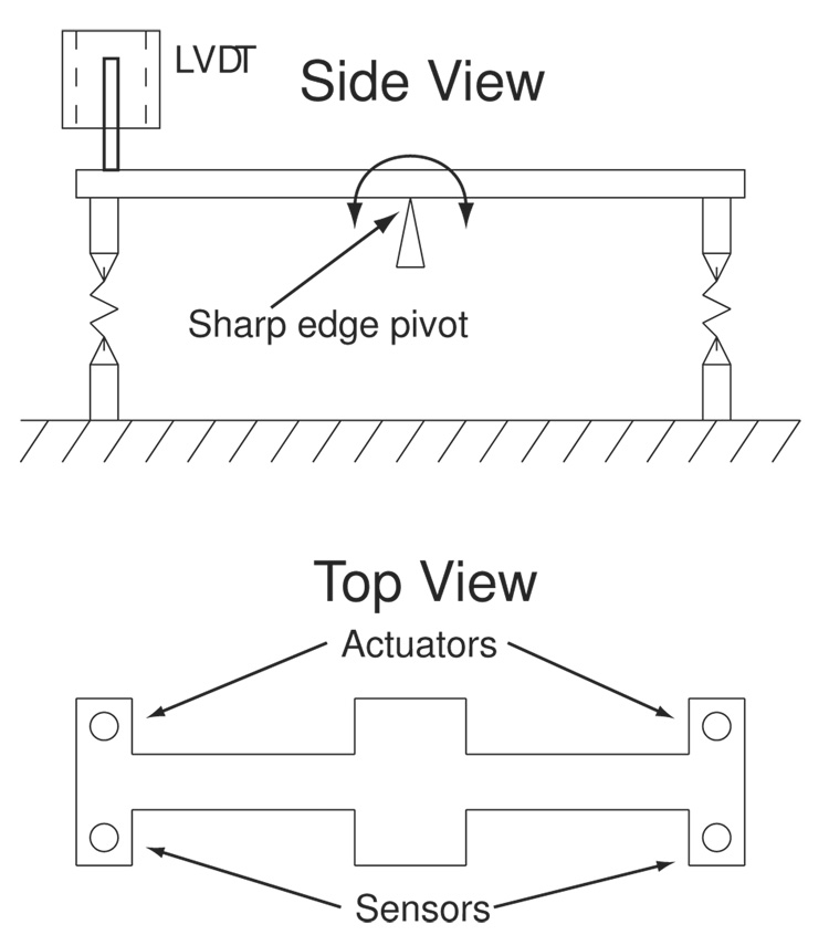
To simulate the configuration of an active catheter, the sensors were also tested dynamically with a balanced beam setup, the schematic of which is shown in Fig. 7. The pivot point simulates the bend point of the catheter joint, and a combination of sensors, actuators, and passive devices are tested.
Fig. 7.
Schematic of dynamic balanced beam setup.
A pair of SMA actuators can be mounted with either one or a pair of sensors to simulate their antagonistic configuration on an active catheter. A linear variable differential transducer (LVDT) provides accurate measurement of the beam deflection. The beam is balanced on a sharp edge to reduce frictional components. With small angle approximations, the sensor motion is kept to pure extension and contraction with minimal out-of-plane bending. All tests were performed at room temperature in an enclosure to prevent air drafts from disturbing the measurements.
The resistances of the sensors were measured using a Wheatstone bridge configuration, an instrumentation amplifier, and a separate 100 Hz single-pole filter for a total gain of 5000 V/V. Data is sampled using a data acquisition card and LabView software (National Instruments, Austin, TX). The SMA actuators were driven with sinusoidal inputs offset by 180 degrees.
VII. EXPERIMENTAL RESULTS AND DISCUSSION
A. Quasi-static Testing
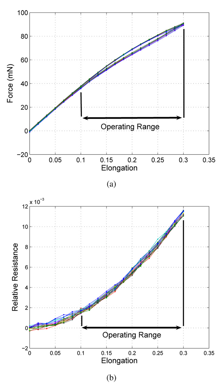
We used the quasi-static results to compare the performance of the different sensor designs. Figure 8 shows the measured force and resistance of one sample of sensor design b stretched to 30 % elongation (450 µm) over 10 cycles. We performed these tests for 10 samples of each design and compiled the data below. Because the value of the absolute resistance should correlate with the overall dimensions of the sensor, we use this as the independent axis of the following quasi-static graphs.
Fig. 8.
(a) Force vs. Elongation for one sample of sensor design b stretched to 30 % elongation (450 µm). (b) Relative Resistance vs. Elongation for the same sensor.
1) Resistance Change
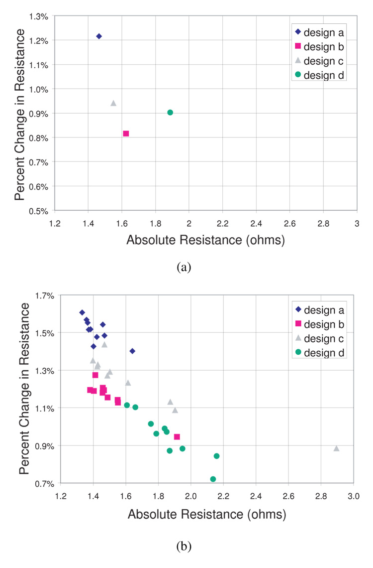
Figure 9a shows the maximum percent resistance change for the four sensor designs at 30% elongation (450 µm) vs. the absolute resistance values as expected from the simulations. Figure 9b shows the experimental results.
Fig. 9.
(a) Simulated percent resistance change at 450 µm elongation vs absolute resistance and (b) experimental percent resistance change at 450 µm elongation vs. absolute resistance for ten samples of each design.
As seen in the figures, the experimental results follow the same basic trends as the simulated values. Some distribution is caused by the manufacturing tolerances of the laser-machining process. Design (d) shows an especially large distribution, likely due greater laser-machining variability with the extra complexity of this the design. Table III shows the simulated and average experimental relative change in resistance for each design, as well as the percent difference between the simulation and experimental values for each design. Although the simulations do not predict the actual resistance output well, the trends in experiment follow the trends in simulation. The error is consistent among the designs within 10 %, which allows us to compare the relative designs in FEA simulation and verify the results in experiment.
TABLE III.
SMA Sensor Simulated vs. Average Experimental Resistance Values
| Design | ΔR/R | ΔR/R | % Diff |
|---|---|---|---|
| (Sim) | (Exp) | ||
| (a) | 1.22 % | 1.51 % | −19 % |
| (b) | 0.82 % | 1.16 % | −29 % |
| (c) | 0.94 % | 1.23 % | −24 % |
| (d) | 0.70 % | 0.95 % | −26 % |
2) Stiffness
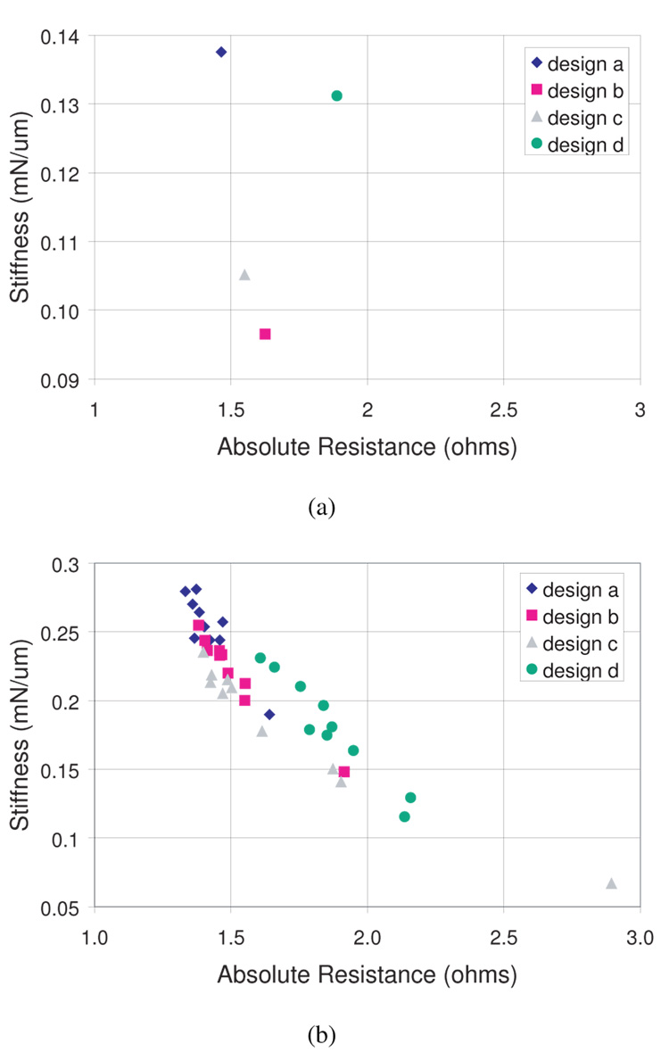
The stiffness of each sensor is estimated by dividing the maximum force by the maximum displacement (450 µm). Figure 10a and Fig. 10b show the simulation and experimental stiffness results, respectively. The data show similar trends to simulation, but the variation in the experimental stiffness data is larger than that for resistance. Since differences in absolute resistance are determined entirely by variations in dimensions and geometry, outliers in the data suggest significant differences in actual vs. desired dimensions due to laser-machining and electropolishing tolerances.
Fig. 10.
(a) Simulated stiffness vs. absolute resistance and (b) measured stiffness vs. absolute resistance for ten samples of each design.
As seen in Table IV, the average experimental stiffnesses follow simulation for each design with a relatively consistent error, although this error is generally higher than that of the resistance values. Again, design (d) does not follow simulation as well, due to its more complex design. However, for a single design, on which only small variations are made (i.e. designs a–c), the average variation in experimental stiffness from simulation is consistent to within 14 %.
TABLE IV.
SMA Sensor Simulated and Average Experimental Stiffness Values
| Design | Stiffness | Stiffness | % Diff |
|---|---|---|---|
| (Sim) | (Exp) | ||
| (a) | .138 | .253 | 46 % |
| (b) | .096 | .222 | 57 % |
| (c) | .104 | .182 | 43 % |
| (d) | .131 | .180 | 27 % |
There are a number of reasons that the relative force characteristics using this model will be less predictable compared to that of the resistances. The perfectly plastic stressstrain model greatly simplifies the stress-strain response of the tubing. Also, the dimensions of the tube strip from which the FEA parameters were derived was itself subject to variations in laser-machining tolerances. For this application, accurate modeling of the force characteristics is not necessary, as long as the sensor stiffness is low compared to that of the actuator These sensors exhibit a maximum of 7 % of the stiffness of the actuator.
The stiffness can be reduced and the absolute resistance can be increased by decreasing the thickness of the sensor. Table V shows a comparison of the absolute resistance, resistance change, and stiffness of design (a) as the sensor thickness is varied in simulation. As shown, the resistance change stays relatively constant, while absolute resistance decreases as the inverse of thickness, and stiffness increases linearly with thickness. The simulation values for the existing sensor design (a) are listed in bold for comparison. In the future, thickness can therefore be used as an additional design parameter.
TABLE V.
Simulated Sensor Characteristics vs. Thickness for Design (A)
| Thickness | R | ΔR/R | Stiffness |
|---|---|---|---|
| (µm) | (Ω) | (%) | (mN/µm) |
| 35 | 3.41 | 1.23 | 0.060 |
| 50 | 2.38 | 1.24 | 0.086 |
| 65 | 1.83 | 1.23 | 0.112 |
| 80 | 1.48 | 1.22 | 0.138 |
| 95 | 1.25 | 1.21 | 0.163 |
3) Hysteresis
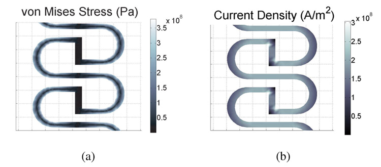
As can be seen from Fig. 8, despite the appearance of significant hysteresis in the mechanical characteristics, the electrical resistance showed little hysteresis. This is likely due to the difference in distribution of mechanical strains in the sensor structure and the distribution of the current density, which determines the overall resistance. The FEA simulations in Fig. 11 show that the high stress areas appear toward the inside edges of the curves, while the high current density areas are in the horizontal struts. Therefore the measurement of resistance is somewhat decoupled from the mechanical response of the structure.
Fig. 11.
(a) Stress and (b) current density plots of the sensor structure, showing the difference in distribution of mechanical strains and electrical.
B. Dynamic Testing
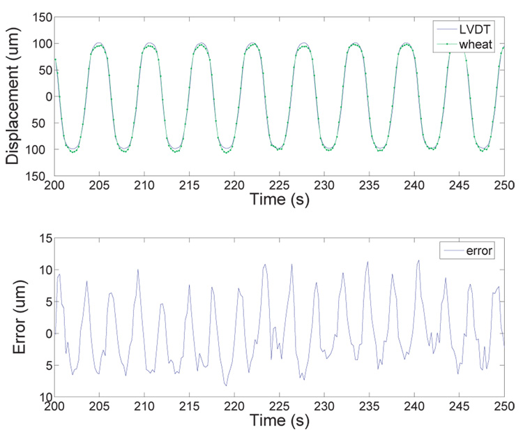
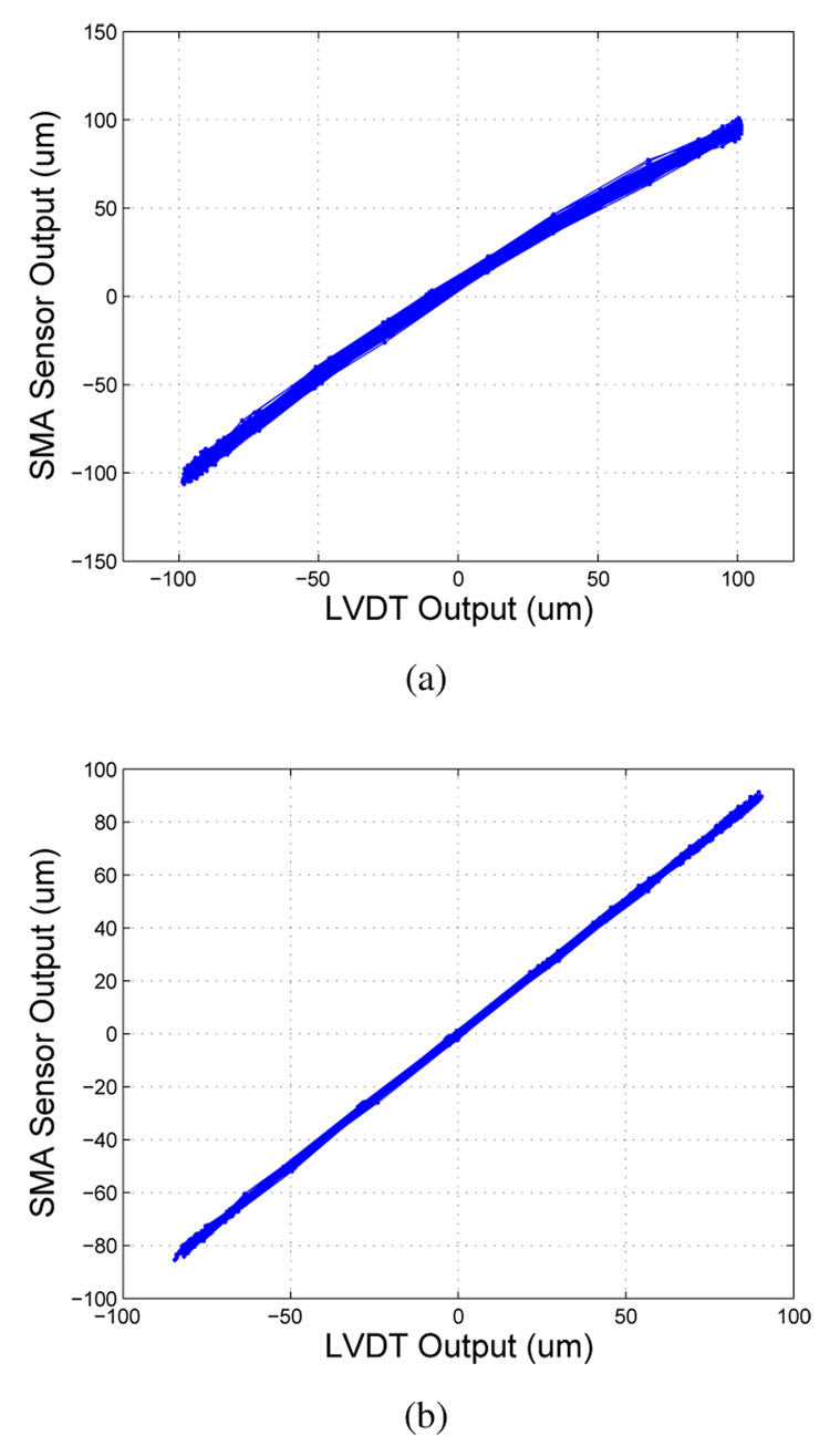
To place the sensors in a configuration that is closer to a real active catheter situation, we performed dynamic testing of a single sensor and two sensors in differential configuration. For the single sensor test, the sensor is balanced in the Wheatstone bridge with a static resistor. In differential configuration, the two sensors form two arms of the bridge. The LVDT output and the scaled Wheatstone output with one sensor of design d are shown in Figure 12 for a 0.3 A amplitude, 0.4 Hz sine input to the actuators. As seen in Figure 13a, the Wheatstone output is mostly linear with the LVDT output, though some curvature is apparent. The RMS error for one sensor compared to the LVDT is 4.9 µm, or 3.4 % of full-scale, with a linear drift of .015 µm/s over 8 minutes and 200 cycles. The raw signal output for the single sensor configuration was ~6 mV/µm from the amplification and filtering stage before scaling.
Fig. 12.
Displacement output of LVDT and Wheatstone bridge vs. time for a single SMA sensor with 0.4 Hz sinusoidal input to the actuators.
Fig. 13.
Comparison of Wheatstone output and LVDT position measurement with 0.4 Hz sine input for (a) a single sensor over 200 cycles and (b)two sensors in differential configuration over 200 cycles.
In differential configuration, the sensors exhibited a similar drift of .015 µm/s but with a lower RMS error of .91 µm, or .52 % over 8 minutes. Figure 13b shows the linear relationship between the Wheatstone output and that of the LVDT over a 174 µm range. The output is linear with the LVDT output. The raw signal output was ~9.6 mV/µm, which is 1.6 times the signal output of the single sensor.
Although a single sensor can be used to track the position of an SMA actuator, the use of two sensors in a differential configuration improves the linearity of the output signal. In theory, differential configuration can produce twice the output signal if the sensors are perfectly balanced and linear. With some sensor nonlinearity and imbalance, the signal output was still 1.6 times that of the single sensor case. In addition, if the sensors are placed closely together as in an active catheter application, differential measurement enables compensation for thermal fluctuations. Use of differential sensing also reduces the common-mode noise in the output and hence the RMS error. The sensor accuracy can be further improved with more complex signal conditioning or a frequency selective modulation scheme. The drift of the sensors is modest and can be compensated with proper calibration prior to use in an active catheter.
C. Manufacturing Variability
Manufacturing tolerances in the laser-machining process reduce the precision of the achievable dimensions and limit the ability of the FEA to predict the characteristics of an individual sensor. However, general trends corresponding to the design changes can be observed in most of the quasi-static results. As seen in Fig. 10 and Fig. 9, the distributions of stiffness and resistance for design (d) were significantly wider than for the other designs, and the (d) results had larger deviation from the expected relative values. This is due to difficulties in obtaining repeatable cut dimensions with the more complex winding geometry.
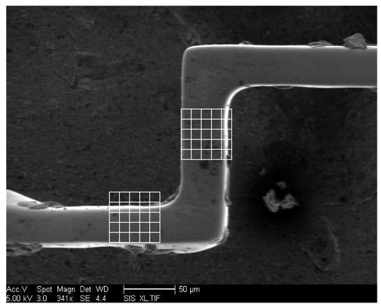
As an example of the manufacturing variability, Fig. 14 shows a scanning electron microscope (SEM) image of a section of a sensor of design (c). The lower horizontal strut was designed to be 40 µm thick, and the vertical strut 50 µm. The actual dimensions are approximately 35 µm and 42 µm, respectively.
Fig. 14.
SEM photograph of a section of one sample of design c. The grid spacing is 10 µm in both directions.
The dimensions of these sensors are near the minimum limits of this laser-machining process, and so the machining tolerances can be quite wide. To mitigate these manufacturing issues, thinner tubing (or increased electropolishing) could be used to trade off the thickness of the tubing for strut thickness while keeping stiffness constant, which would allow for thicker struts that can be cut more precisely. The above data indicate, however, that the rapid cycling of FEA simulations and experimental verification can enable the design of sensors with the desired relative characteristics despite the manufacturing tolerances.
VIII. CONCLUSION
We have demonstrated a method for producing small-scale SMA resistance sensors for active catheters based on a rapid prototyping platform of simple FEA, laser-machining and electropolishing of nitinol tubes, and experimental testing. We have shown that this process can be used to alter the signal output and reduce stiffness of the sensors with a few dimensional changes. Many geometries and dimensions are possible and are limited only by the tolerances of the laser-machining and electropolishing processes, and by the application itself. With proper amplification and compensation, the sensors have low RMS error and drift and can function as linear position sensors, especially when used differentially.
Future work will include integration of the sensors with SMA actuators on an active catheter substrate and testing their performance in position sensing. Particular attention will be devoted to signal-conditioning and thermal sensitivity, which a differential configuration should help to mitigate. Further refinements of the design process, including developing methods to optimize the stress distribution and improve signal output, will further improve the sensor performance. We believe this path will enable the practical use of SMA materials, especially in their application to active catheters, and ultimately improve medical devices and benefit patient care.
IX. ACKNOWLEDGMENTS
The authors would like to thank the National Institutes of Health for partially funding this work.
Biographies

Alexander T. Tung Alex Tung received B.S. and M.S. degrees in electrical engineering from Stanford University in 2000 and 2002, respectively. He is currently pursuing a Ph.D. degree in electrical engineering, also at Stanford University. His research interests are in medical device technology, surgical robotics, and medical electronics.

Byong-Ho Park Byong-Ho Park received his B.S. degree with Honors from Han Yang University, Republic of Korea, in 1996. He earned his M.S. and Ph.D. degree in Mechanical Engineering from Stanford University, Stanford, in 1998 and 2002, respectively. In 2002, he received the Dean’s Postdoctoral Fellowship in the School of Medicine at Stanford University. In 2003, he joined as a Research Associate in the Department of Mechanical Engineering at Stanford University. Currently, he is on leave from Stanford University, working on biomedical device research and development at the Fluid Medical Inc., Mountain View.

David H. Liang Dr. David H. Liang received his BS degree in 1981 from the Massachusetts Institute of Technology in electrical engineering, and his MSEE (1984), Ph.D. (1989) and MD (1989) degrees from Stanford University. He conducted his residency in Internal Medicine (1989–92) and fellowship in Cardiovascular Medicine (1992–95) at Stanford University Medical Center. Since 1998 he has been on the faculty in the Division of Cardiovascular Medicine at Stanford University with a courtesy appointment in the Department of Electrical Engineering at Stanford.
His current research interests are in cardiac imaging, image guided intervention and device development for minimally invasive therapy.

Günter Niemeyer Dr. Günter Niemeyer is an assistant professor in Mechanical Engineering at Stanford University and directs the Telerobotics Lab. His research examines human-robotic interactions, force sensitivity, control, and display, and teleoperation. Medical devices, in particular interventional devices, form a primary application. His work also addresses haptic feedback and the effects of delayed or network transmissions on user perception, both in training, simulation, and operation.
Dr. Niemeyer received his M.S. and Ph.D. from MIT in the areas of adaptive robot control and bilateral teleoperation, introducing the concept of wave variables. He also held a postdoctoral research position at MIT developing surgical robotics. In 1997 he joined Intuitive Surgical Inc., where he helped create the daVinci Minimally Invasive Surgical System. This telerobotic system enables surgeons to perform complex procedures through small (5 to 10mm) incisions using an immersive interface and is now being used at hundreds of hospitals worldwide. He joined the Stanford faculty in the Fall of 2001.
Footnotes
Publisher's Disclaimer: This is a PDF file of an unedited manuscript that has been accepted for publication. As a service to our customers we are providing this early version of the manuscript. The manuscript will undergo copyediting, typesetting, and review of the resulting proof before it is published in its final citable form. Please note that during the production process errors may be discovered which could affect the content, and all legal disclaimers that apply to the journal pertain.
REFERENCES
- 1.Pappone C, Rosanio S, Oreto G, Tocchi M, Gugliotta F, Vice-domini G, Salvati A, Dicandia C, Mazzone P, Santinelli V, Gulletta S, Chierchia S. Circumferential radiofrequency ablation of pulmonary vein ostia : A new anatomic approach for curing atrial fibrillation. 2000 November 21;:2619–2628. doi: 10.1161/01.cir.102.21.2619. [DOI] [PubMed] [Google Scholar]
- 2.Ernst S, Ouyang F, Lober F, Antz M, Kuck KH. Catheter-induced linear lesions in the left atrium in patients with atrial fibrillation: an electroanatomic study. J Am Coll Cardiol. 2003;vol. 42(no 7):1271–1282. doi: 10.1016/s0735-1097(03)00940-9. [DOI] [PubMed] [Google Scholar]
- 3.Ikuta K, Tsukamoto M, Hirose S. Shape memory alloy servo actuator system with electric resistance feedback and application for active endoscope; 1988 IEEE International Conference on Robotics and Automation; 24–29 April 1988; Philadelphia, PA, USA. 1988. pp. 427–430. [Google Scholar]
- 4.Haga Y, Esashi M, Maeda S. Bending, torsional and extending active catheter assembled using electroplating; IEEE Thirteenth Annual International Conference on Micro Electro Mechanical Systems; 23–27 Jan. 2000; Miyazaki, Japan. Piscataway, NJ, USA: IEEE; 2000. pp. 181–186. [Google Scholar]
- 5.Park K, Esashi M. Mulitlink active catheter with polyimide-based integrated cmos interface circuits. Journal of Microelectromechanical Systems. 1999;vol. 8(no 4):349–357. [Google Scholar]
- 6.Langelaar M, van Keulen F. Modeling of a shape memory alloy active catheter; 45th AIAA/ASME/ASCE/AHS/ASC Structures, Structural Dynamics and Materials Conference; Palm Springs, CA: 2004. pp. 1–16. [Google Scholar]
- 7.Liang C, Rogers CA. One-dimensional thermomechanical constitutive relations for shape memory materials. J. of Intell. Mater. Syst. and Struct. 1990 April;vol. 1:207–234. no. [Google Scholar]
- 8.Raparelli T, Zobel PB, Durante F. Sma-wire position control with electrical resistance feedback; Proc 3rd World Conf. on Structural Control; Como, Italy: 2002. pp. 391–398. [Google Scholar]
- 9.Ma N, Song G, Lee H-J. Position control of shape memory alloy actuators with internal electrical resistance feedback using neural networks. Smart Materials and Structures. 2004;vol. 13:777–783. [Google Scholar]
- 10.Song G, Chaudhry V, Batur C. A neural network inverse model for a shape memory alloy wire actuator. Journal of Intelligent Material Systems and Structures. 2003;vol. 14:371–377. [Google Scholar]
- 11.Tung AT, Park B-H, Koolwal A, Nelson B, Niemeyer G, Liang DH. Design and fabrication of shape memory alloy tubular actuators for active catheters; The First IEEE/RAS-EMBS International Conference on Biomedical Robotics and Biomechatronics, 2006. BioRab 2006; Pisa, Italy: 2006. pp. 775–780. [Google Scholar]
- 12.Koolwal AB, Park B-H, Nelson B, Niemeyer G, Liang DH. Amplitude-modulating switching feedback for position control of shape memory alloy actuators; The First IEEE/RAS-EMBS International Conference on Biomedical Robotics and Biomechatronics, 2006. BioRob 2006; Pisa, Italy: 2006. pp. 847–852. [Google Scholar]
- 13.Tung AT, Park B, Niemeyer G, Liang DH. Laser-machined shape memory alloy actuators for active catheters. Mechatronics, IEEE/ASME Transactions on. 2007;vol. 12(no 4):439–446. 1083–4435. [Google Scholar]
- 14.Wu XD, Wu JS, Wang Z. The variation of electrical resistance of near stoichiometric niti during thermo-mechanic procedures. Smart Mater. Struct. 1999;vol. 8:574–578. [Google Scholar]
- 15.Nahm SH, Kim YI, Kim JM, Yoon DJ. A study on the application of ni-ti shape memory alloy as a sensor. Materials Science Forum. 2005;vol. 475–479:2043–2046. [Google Scholar]
- 16.Chang JK, Chung S, Lee Y, Park J, Lee S-K, Yang SS, Moon S-Y, Han D-C. Intravascular micro active catheter for minimal invasive surgery. In: Dittmar A, Beebe D, editors. 1st Annual International IEEE-EMBS Special Topic Conference on Microtechnologies in Medicine and Biology. Proceedings; 12–14 Oct. 2000; Lyon, France. Piscataway, NJ, USA: IEEE, 2000; 2000. pp. 243–246. [Google Scholar]
- 17.Takizawa H, Tosaka H, Ohta R, Kaneko S, Ueda Y. Development of a microfine active bending catheter equipped with mif tactile sensors; Twelfth IEEE International Conference on Micro Electro Mechanical Systems; 1999. pp. 412–417. [Google Scholar]
- 18.Kohl M. Shape Memory Microactuators. New York: Springer; 2004. [Google Scholar]
- 19.Tung AT, Park B-H, Niemeyer G, Liang DH. International Conference on Shape Memory and Superelastic Technologies. Pacific Grove, CA: 2006. Shape memory position sensor for feedback control of active catheters. [Google Scholar]
- 20.Window A, editor. Strain Gauge Technology. 2nd ed. New York: Elsevier Applied Science; 1992. [Google Scholar]
- 21.Ikuta K. Micro/miniature shape memory alloy actuator; 1990 IEEE International Conference on Robotics and Automation; 13–18 May 1990; Cincinnati, OH, USA. 1990. pp. 2156–2161. [Google Scholar]
- 22.Dutta S, Ghorbel F. Differential hysteresis modeling of a shape memory alloy wire actuator. Mechatronics, IEEE/ASME Transactions on. 2005;vol. 10(no 2):189–197. [Google Scholar]


