

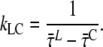
Abstract
Over the past several years, many crystal structures of photosynthetic pigment-protein complexes have been determined, and these have been used extensively to model spectroscopic results obtained on the same proteins in solution. However, the crystal structure is not necessarily identical to the structure of the protein in solution. Here, we studied picosecond fluorescence of photosystem I light-harvesting complex I (PSI-LHCI), a multisubunit pigment-protein complex that catalyzes the first steps of photosynthesis. The ultrafast fluorescence of PSI-LHCI crystals is identical to that of dissolved crystals, but differs considerably from most kinetics presented in the literature. In contrast to most studies, the data presented here can be modeled quantitatively with only two compartments: PSI core and LHCI. This yields the rate of charge separation from an equilibrated core (22.5 ± 2.5 ps) and rates of excitation energy transfer from LHCI to core (kLC) and vice versa (kCL). The ratio between these rates, R = kCL/kLC, appears to be wavelength-dependent and scales with the ratio of the absorption spectra of LHCI and core, indicating the validity of a detailed balance relation between both compartments. kLC depends slightly but nonsystematically on detection wavelength, averaging (9.4 ± 4.9 ps)−1. R ranges from 0.5 (<690 nm) to ∼1.3 above 720 nm.
INTRODUCTION
The primary steps of photosynthetic conversion of solar energy into chemical energy occur in membrane-bound photosystems (PSs). These photosystems are highly organized pigment-protein complexes. In oxygen-evolving photosynthesis, two photosystems, PSII and PSI, work in series to drive electrons from water to NADP+. In higher plants, PSI forms a supercomplex called PSI light-harvesting complex I (PSI-LHCI), consisting of a core complex and four LHCIs. The core complex consists of 15 proteins that bind ∼103 chlorophylls (Chls) a, ∼20 carotenoids (Cars), three [4Fe4S] clusters, and two phylloquinones (1–4). It contains the reaction center (RC), with six Chls, which is responsible for charge separation upon excitation. In higher plants, four LHCIs, which bind together 56 Chls a and b (1) and ∼10 Cars (5,6), are attached to one side of the core (7). In addition, nine Chls fill the gap between LHCI and core (1,2), and it has been proposed that these Chls mediate energy transfer from LHCI to the core (8,9). The pigments bound to PSI-LHCI fulfill various functions: light-harvesting, charge-separation and electron transport (in the RC), and photoprotection (4). The pigment density in PSI is higher than in PSII, and in contrast to PSII, PSI contains Chls that are substantially lower in excited-state energy (“red” Chls) than the RC Chls (10). Moreover, the energy transfer from light-harvesting pigments to RC is faster and more efficient in PSI (for an overview, see (11,12)).
The core complex of higher plants and cyanobacteria is highly conserved concerning protein composition and protein and pigment organization (1,3). However, the spectroscopic properties of individual cyanobacteria species, higher plants, and red algae differ substantially due to the presence of the red Chls, which have diverse energies and abundance in the different systems (13,14). In higher plants, the red Chls are mainly associated with the outer antenna and in particular with Lhca3 and Lhca4 (15–17). The transfer of excitation energy from these low-energy forms to the RC is a thermally activated process (18) and it has a large influence on the excitation trapping time of the system (13,19,20). The most advanced compartmental modeling studies on PSI all include at least one compartment that contains red pigments.
The excited-state dynamics of PSI has been studied extensively by time-resolved fluorescence and rather large variations have been observed (8,20–25). In general bi- and triexponential decays are observed for PSI from higher plants (8,20–25). The fastest component (5–20 ps) is attributed partially to energy transfer from bulk to low-energy chlorophylls and partially to trapping. The second component (20–60 ps) is generally attributed to the trapping from the core complex, and the origin of a slower decay (80–130 ps) is under debate (26). The shape and the relative intensities of the second and third decay components differ considerably for the various studies, especially in the red part of the spectrum. This suggests differences in the content of the red forms and/or LHCI-core connectivity for the various preparations. Also, the interpretation of the results varies: from a trap-limited model in which the excitation-energy migration time is largely neglected (24) to a model in which both migration and charge separation contribute to the trapping kinetics (8,22), even for cyanobacteria, in which LHCI is absent (27).
Several theoretical studies have used the x-ray structures of pea PSI-LHCI (1,2) and cyanobacterial PSI core (3) to model the excited-stated dynamics (9,26,28–30). However, it is not trivial that the structure and dynamics of a pigment-protein complex are the same in solution and in crystal form. For example, LHCII, which is part of the PSII supercomplex, shows clear differences in fluorescence and Raman properties for solubilized and crystallized forms (31).
Therefore, it is not known a priori whether excited-state properties obtained from theoretical studies based on the PSI-LHCI crystal structure reflect those of PSI-LHCI in solution. This complicates the comparison of results from the theoretical studies with experimental data (which, moreover, have large variations, as noted above). For these reasons, we have measured the excited-state dynamics of PSI-LHCI crystals, and compared the results with those obtained for solubilized PSI-LHCI crystals. The excited-state dynamics in these two samples were indistinguishable, thus indicating very similar structure and dynamics. Comparison with previously reported fluorescence kinetics shows that many differ from those of the crystals. A novel approach is applied to unveil i), the fluorescence kinetics after selective excitation of either core or LHCI, ii), the trapping time from the equilibrated core in the presence of the antenna, iii), the rates of excitation-energy transfer from core to LHCI and vice versa, and iv), to explain the wavelength dependence of the overall trapping time.
MATERIALS AND METHODS
PSI-200 crystal preparation
PSI-LHCI was isolated from Pisum sativum (pea), and crystallized as described in Amunts et al. (32).
Pigment composition
PSI-LHCI crystals were dissolved in 80% acetone, and the precipitate was removed by centrifugation. Absorption spectra were recorded on a Cary 5E UV-Vis-NIR (Varian, Palo Alto, CA). The pigment composition was analyzed by high-performance liquid chromatography, and fitting of the absorption spectra of the acetone extracts was as in Croce et al. (33). Values of 8.5 ± 0.1 for the Chl a/b ratio and of 5.2 ± 0.1 for the Chl/Car ratio were obtained. Out of the 168 Chls, 150 are Chls a and 18 are Chls b, and there are 19 β-carotenes, 8 luteins, and 5 violaxanthins.
Time-correlated single photon counting (TCSPC)
PSI-LHCI crystals were solubilized in measuring buffer (10 mM Tricine pH 7.8). Steady-state fluorescence emission spectra, which are necessary to calculate decay-associated spectra (DAS), were measured after excitation at 410 nm or 475 nm on a Spex Fluorolog 3.2.2 (HORIBA Jobin-Yvon, Edison, NJ). Fluorescence decay curves were measured by TCSPC using a home-built setup (34). In brief, vertically polarized excitation pulses were used (wavelength 410 nm or 475 nm, pulse duration 200 fs, repetition rate 3.8 MHz). Fluorescence was collected at right angles to the excitation beam, at a rate of ∼30,000 counts/s, and care was taken to minimize data distortion (35). The fluorescence light was detected at magic-angle polarization through interference filters of 679, 693, 707, and 713 (Schott, Mainz, Germany), 724.1, 734.1, 744.1, and 759.4 nm (Balzer B-40, Rolyn Optics, Covina, CA). The interference filters were tilted by 5° to prevent reflections. Under the same angle, the filters' transmission spectra were measured on the Cary 5E UV-Vis-NIR spectrophotometer. The spectral widths were 10–15 nm, and transmission maxima were as indicated (see Fig. 3). Detection times were stored in a multichannel analyzer (4096 channels at 2.0 ps time spacing). All measurements were performed at 287 K, and the number of counts in the peak channel was 30,000–50,000.
FIGURE 3.

Decay-associated spectra of PSI-LHCI in solution at 287 K, excited at 410 nm (solid lines) and at 475 nm (dashed lines). DAS are scaled on the total area of the 61 ps and 143 ps DAS. The slowest three components are presented in more detail in Fig. S11, Data S1.
Curves measured at different excitation and detection wavelengths were globally fitted to a sum of exponential decays that was convoluted with the instrument response function (IRF, ∼60 ps full width at half-maximum), using home-built software (36). The IRF was determined from the fast decay of pinacyanol iodide in methanol (6 ps, as measured with the streak camera detection system (see below)). The fitting resulted in DAS. The fit quality was evaluated from χ2, and from plots of the weighted residuals and the autocorrelation thereof. To obtain a good fit for all combinations of excitation and detection wavelength, at least six decay times are needed. The accuracy of  and of
  (see below) was tested by fixing the fastest lifetime at different values between 15 and 30 ps and reoptimizing the fit of the fluorescence-decay traces. The effect appeared to be negligible.
To compare the fit results of PSI-LHCI in solution with PSI-LHCI crystals, decay curves were constructed from the DAS (taking into account the spectral sensitivity of the fluorescence lifetime imaging microscope (FLIM)), and convoluted with the IRF of the FLIM, using a reference convolution routine (37).
Fluorescence lifetime imaging microscopy
Time-resolved fluorescence of PSI-LHCI crystals was measured by FLIM, with the setup as previously described (38). In short, two-photon excitation pulses (wavelength 860 nm, pulse duration 150 fs, repetition rate 76 MHz) were focused into the sample with a 60× water immersion objective lens (CFI Plan Apochromat, numerical aperture 1.2, Nikon, Tokyo, Japan). Fluorescence was detected via nondescanned single-photon counting detection, through two bandpass filters of 700 nm (75 nm in width) (HQ700/75 Chroma, McHenry, IL), or one bandpass filter of 730 nm (45 nm in width) (XF1097 730AF45, Omega Optical, Brattleboro, VT). Images of 32 × 32 pixels were obtained, with 4096 time channels of 3.1 ps. Typically, one crystal occupied 300–600 pixels of the image.
Care was taken to prevent sample degradation by drying and photobleaching at very high light intensities. Drying led to an increase of the fluorescence lifetime, and was prevented by addition of mother liquid (for composition, see Amunts et al. (1)). Increasing the power 1000-fold by focusing all light on a single pixel led to bleaching: The fluorescence lifetime increased, the total fluorescence decreased, and spots of decreased fluorescence were visible by eye. At lower light intensity, the signal intensity scaled linearly with the square of the excitation power, confirming excitation via two-photon absorption. Fluorescence kinetics did not depend on excitation light intensity in the power range used for these experiments (0.03–0.30 mW, Supplementary Material, Fig. S10 in Data S1). Each crystal was measured several times, and the results were indistinguishable. In total, tens of crystals were measured.
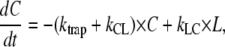
Fitting of the fluorescence kinetics per pixel showed little variation within and between crystals (Fig. 1). Therefore, the fluorescence decay curves of all pixels of a crystal were summed and analyzed with home-built software (36). The curves were fitted to a sum of exponential decays, convoluted with the IRF (25 ps), which was determined from the decay of pinacyanol iodide in methanol. Because of the relatively large background intensity, decay curves were not fitted beyond 1 ns.
FIGURE 1.

Fluorescence lifetime image of a PSI-LHCI crystal, measured at room temperature. False colors represent the average lifetimes at each pixel. The histogram represents the frequency of occurrence of the average lifetime calculated from a two-component fit. Excitation was at 860 nm, detection at 670–730 nm (left, average lifetime 40 ps) or at 710–750 nm (average lifetime 51 ps). Color scale: 30 ps (green) to 60 ps (blue).
The fluorescence decay traces obtained with FLIM are of lower quality than those obtained with TCSPC. Several factors are responsible for this.
In FLIM, the number of photons detected per pixel is low compared to TCSPC. This results in larger (Poissonian) noise. Summing up the decay curves of all pixels containing crystal-fluorescence partially overcomes this problem.
The time channels are wider in FLIM (3.1 ps) than in TCSPC (2 ps).
FLIM has a larger background signal, due to slightly worse shielding of background light.
The IRF of FLIM contains more artifacts due to reflections, caused by the larger amount of optics between sample and detector.
The IRF can be determined less accurately with FLIM, because the reference compound is in solution, whereas the sample is semisolid (crystals). However, the IRF is narrower than for TCSPC.
Despite all these limitations, we were able to obtain high time resolution with the FLIM data, and we could compare the fluorescence kinetics with those obtained by TCSPC of PSI-LHCI in solution.
Streak camera
Time-resolved fluorescence of pinacyanol iodide (Exciton, Dayton, OH) in methanol was measured on a picosecond timescale, with the set of lasers and the synchroscan streak-camera detection system described in detail elsewhere (39). In short, vertically polarized excitation pulses (400, 475, or 530 nm, 200 fs duration, 253 kHz repetition rate, 1 mW) were focused to a 150-μm spot in a static cuvette containing the sample. Fluorescence was focused into the spectrograph, at a right angle to the excitation beam, and at magic-angle polarization. The spectrograph horizontally dispersed the fluorescence spectrum into the streak camera, where it was vertically dispersed as a function of time. Streak images obtained by the CCD camera were corrected for nonlinearity of the time- and wavelength axes, and the sensitivity of the detection system. The corrected streak images represent two-dimensional datasets of fluorescence intensity as a function of time and wavelength, with spectral resolution 2 nm, and temporal resolution ∼1 ps. The images were sliced up into traces of 2 nm width, and fitted by global analysis to a sum of exponentials, using software described in van Stokkum et al. (40). The resulting wavelength-dependent amplitudes provide the DAS. The fluorescence of pinacyanol decays mainly monoexponentially, with a lifetime of 6 ps (DAS shown in Fig. S9, Data S1), at all excitation wavelengths, with a small contribution from solvent relaxation after 530 nm excitation. The kinetics was independent of concentration, and not affected by reabsorption. The 6 ps is of higher precision than the previously reported values, which ranged from 4 to 10 ps (41–46), and therefore increases the accuracy of TCSPC experiments when pinacyanol is used as a reference to determine the instrument response function.
RESULTS
PSI-LHCI crystals
The fluorescence kinetics of a single crystal at different excitation intensities is shown in Fig. S10, Data S1. The fluorescence kinetics was indistinguishable for excitation intensities varying 10-fold (0.03–0.30 mW), i.e., a 100-fold variation of the number of excited states. During all experiments, the power was within this range. Thus, in these experiments the effects of closing reaction centers and/or bleaching and annihilation are negligible.
FLIM experiments comprise TCSPC experiments in each pixel of a microscope image. These individual traces were fitted to a biexponential decay. Fig. 1 shows a false-color image of the result of such a fit for a single PSI-LHCI crystal, detected at 670–730 nm (left) or 710–750 nm (middle). The color encodes for the average fluorescence lifetime, calculated from the biexponential fit. A frequency histogram of the average lifetime distribution is also shown (right). It is clear that the fluorescence lifetime is nearly the same in all pixels. Therefore, the signals of all pixels were summed to increase the signal intensity.
Time-resolved fluorescence of tens of PSI-LHCI crystals was measured. The fluorescence kinetics was identical for all crystals, with only a few exceptions. The fluorescence decay curves of the crystals with the highest signal/noise ratio were analyzed further. Three of these decay curves are presented in Fig. 2. As in Fig. 1, the fluorescence decay is faster in the 670–730 nm interval than in the 710–750 nm interval. The decay curves of the five crystals with highest signal intensity were analyzed together, using global analysis, fitting simultaneously the decays at both detection wavelengths. At least three exponentials were needed for a good description of the data, yielding the parameters given in Table 1 (four exponentials gave a negligibly better fit). The main decay lifetimes are ∼26 ps (71 ± 2% at 670–730 nm and 57 ± 1% at 710–750 nm), and ∼67 ps (26 ± 2% and 37 ± 1%). The third lifetime (≈244 ps) contributes ≈<5%. No components with negative amplitude (indicative of energy transfer) were found. These are probably faster than the time resolution of our FLIM setup.
FIGURE 2.

Normalized sums of fluorescence decay curves of three different PSI-LHCI crystals measured at room temperature with FLIM. Excitation was at 860 nm, detection at 670–730 nm (solid lines) and 710–750 nm (dotted lines).
TABLE 1.
Fluorescence decay parameters of PSI-LHCI crystals and PSI-LHCI in solution
| PSI-LHCI crystal
|
PSI-LHCI in solution
|
||||||
|---|---|---|---|---|---|---|---|
| Excitation:
|
860 nm
|
410 nm
|
475 nm
|
||||
| Detection:
|
670–730 nm
|
710–750 nm
|
|
670–730 nm
|
710–750 nm
|
670–730 nm
|
710–750 nm
|
| τ (ns) |  |
 |
τ (ns) | psol | psol | psol | psol |
| 0.026 | 0.710 (0.020) | 0.570 (0.012) | 0.024 | 0.722 | 0.551 | 0.665 | 0.509 |
| 0.067 | 0.256 (0.021) | 0.369 (0.013) | 0.061 | 0.208 | 0.334 | 0.257 | 0.362 |
| 0.244 | 0.035 (0.000) | 0.060 (0.002) | 0.143 | 0.063 | 0.104 | 0.079 | 0.117 |
| 0.37 | 0.006 | 0.011 | 0.008 | 0.012 | |||
Amplitudes pcryst are the average of a global fit of the five crystals with highest signal intensities, with standard deviation given in parentheses (more details in text). Three of these decay traces are shown in Fig. 2. Amplitudes psol are calculated from the DAS in Fig. 3, without the nanosecond components (more details in text), such that they represent the same spectral window as used for the crystals.
PSI-LHCI in solution
An important question is whether the fluorescence kinetics of PSI-LHCI crystals is the same as that of PSI-LHCI in solution. To sort this out, the crystals were solubilized and the steady-state and time-resolved fluorescence were measured. The excitation wavelength was 410 nm or 475 nm, and the detection ranged from 670 to 760 nm. To obtain a good fit of the fluorescence decay traces at all combinations of excitation and detection wavelengths, at least six decay times are needed. Scaling the results of the fitting with the steady-state emission spectra yields the DAS (see Fig. 3). The main lifetimes are 24 ps (23.7–24.4 ps), 61 ps (60.4–61.5 ps) and 143 ps (141–146 ps). The 95% confidence intervals calculated by exhaustive search are given in parentheses. The 24 ps DAS peaks around 690 nm, whereas the other DAS show a red-shift, typical for PSI-LHCI. The red-shift becomes larger with increasing DAS lifetime, as observed previously (21). The nanosecond slow components with small amplitudes may arise from very small amounts of disconnected LHCI and free chlorophyll. The contribution of this slow component is much smaller than in most other studies. The shapes and intensities of the DAS are independent of excitation wavelength, except for the 24 ps DAS: the integrated intensity is ∼20% larger after 410 nm excitation than after 475 nm excitation (Fig. 3). It should be noted that the DAS mainly serve as a relatively simply description of the decay curves. As is argued in Appendix A, the decay times are expected to differ at different wavelengths.
At first sight, the lifetimes and amplitudes of PSI-LHCI crystals (Table 1) and PSI-LHCI in solution (Fig. 3) are rather similar. To perform a quantitative comparison, we calculated the weighted average of the DAS for the FLIM detection regions (670–730 nm or 710–750 nm), taking into account the spectral sensitivity of the FLIM detection system (determined by the optics and detector). The resulting relative amplitudes are presented in Table 1. This shows that the fluorescence kinetics of PSI-LHCI crystals are very similar to those of PSI-LHCI in solution when excited at 410 nm, upon both “blue” (670–730 nm) and “red” (710–750 nm) detection.
To determine to what extent the small differences between PSI-LHCI crystals and PSI-LHCI in solution are due to uncertainty in the fitting, we used a more direct way of comparing the two datasets: the multiexponential decay of PSI-LHCI in solution (constructed from Table 1) was convoluted with the instrument response function of the FLIM setup and subsequently compared with the experimental decay curves of PSI-LHCI crystals. It is clear that the fluorescence kinetics of PSI-LHCI in crystal and in solution are the same at 410 nm, and only slightly different at 475 nm excitation (Fig. 4 A).
FIGURE 4.

Sums of fluorescence decay curves of a PSI-LHCI crystal, and reconstructed from the fits of PSI-LHCI in solution (A) (see Table 1), or from fluorescence kinetics taken from the literature (B and C), after correcting for FLIM sensitivity, convoluting with the IRF, and adding some background signal. Excitation was as indicated in the legend. Detection was as indicated in the legend (A), at 670–730 nm (B), or at 710–750 nm (C). Fluorescence kinetics in B and C are from ref. A (25); ref. B (22); ref. B′ (22) with 65% glycerol; ref. C (21); ref. D (23); ref. E (20); ref. F (8); and ref. G (24).
DISCUSSION
PSI-LHCI crystals versus PSI-LHCI in solution
The fluorescence kinetics of PSI-LHCI depend on excitation wavelength (Fig. 3), as shown previously (20,23). This is due to excitation of different pigments at different wavelengths, which leads to a wavelength-dependent initial excitation distribution over the PSI core and LHCI. The fluorescence kinetics of PSI-LHCI crystals, after excitation at 860 nm, is identical to that of PSI-LHCI in solution after excitation at 410 nm, but not after excitation at 475 nm (Fig. 4 A). This implies excitation of the same pigment-protein complexes at 860 nm and 410 nm. The pigments in PSI-LHCI can roughly be divided into three groups: core pigments, LHCI pigments, and low-energy (red) Chls. Below 500 nm, the red Chls cannot be excited selectively, so the focus is on the core/LHCI ratio of excited pigments. At 410 nm, ∼65% of the excitations are created on core Chls; at 475 nm, this is ∼30% (based on the absorption spectra in Appendix B, and taking into account the 70% Car-to-Chl transfer efficiency in the core (47) and ∼85% in LHCI (E. Wientjes, unpublished results)). It is unfortunate that the two-photon absorption spectra of PSI and LHCI are not available. If only Cars show two-photon absorption of 860 nm light and transfer energy to Chl, then ∼60% of the excitations will “start” on core Chls and ∼40% on LHCI Chls (based on Car contents reported previously (1,5,6) and Car-to-Chl energy transfer efficiency of 70% in the core and 80–90% in LHCI). If only Chl a absorbs at 860 nm, then 65% of the excitations are created in the core and 35% in LHCI. The two-photon absorption of Chl b is 25 times weaker than that of Chl a (48) and is not taken into account. Thus, the initial excitation distribution is 60–65% on the core, and 35–40% on LHCI, using 860 nm light, very similar to what is calculated for 410 nm excitation. This explains why the fluorescence decay kinetics of PSI-LHCI crystals closely resembles that of PSI-LHCI in solution at 410 nm excitation, but not at 475 nm. We conclude that in this preparation of PSI-LHCI from Pivum sativum (pea), the fluorescence kinetics is the same in crystals as in solution.
Previous studies on PSI-LHCI showed quite a large variation of fluorescence kinetics (see Introduction). In general, three major decay times are found: 5–20 ps, 20–60 ps, and 80–130 ps (8,20–25). The decay times and spectra depend on the type of detergent and its concentration (25), the presence of glycerol (22), and excitation wavelength (20,23). The kinetics may further depend on preparation method and plant species. It is of interest to use the atomic structure obtained by x-ray crystallography (1) to explain the observed kinetics (9,26,28). However, the structure of the different preparations of PSI-LHCI in solution is not necessarily the same as that of pea PSI-LHCI in its crystal lattice. Therefore, the question arises, which of the available experimental kinetics corresponds to that of the crystal structure?
To answer this question, the fluorescence decay curves were constructed for the kinetics reported in previous studies (8,20–25) and solubilized crystals (Table 1). Next, these curves were corrected for spectral sensitivity of the FLIM detection system, and convoluted with the IRF. The resulting curves are compared with the experimental FLIM data: in Fig. 4 A for PSI in solution, as measured in this study, and in Fig. 4, B and C, for several literature values (8,20–25). Experiments from the literature were all performed at excitation wavelengths that led to ∼65% core excitation, except for that of Ihalainen et al. (23) (∼30% and ∼48% core excitation at 475 nm and 710 nm, respectively), as can be concluded from the absorption spectra in Appendix B, assuming 70% Car-to-Chl transfer efficiency in the core and 80–90% in LHCI. The curves in Fig. 4 clearly show the large variety in reported fluorescence kinetics. At 670–730 nm (8,20,24,25) and at 710–750 nm (22,24) the kinetics from previous studies,resemble those of the crystals. Only the kinetics reported by Slavov et al. (24) resemble (but are not identical to) those of the crystals at both wavelengths. Particularly at 670–730 nm, their kinetics are faster than observed for the crystals. This is in contrast to the kinetics of solubilized PSI-LHCI crystals, which strongly resemble those of the crystals in both wavelength ranges. Therefore, curves in Fig. 4 serve as a warning, setting limits to the possibility of structure-based modeling of the fluorescence kinetics presented in literature. It is important to realize that the crystallization step requires extremely homogeneous PSI-LHCI, and thereby guarantees very small heterogeneity of the preparation (heterogeneity can be due to partial dissociation of LHCI, of other subunits, or of pigments), as illustrated by the very small intensity of the nanosecond DAS (Fig. 3).
PSI-LHCI in solution
The data on PSI-LHCI in solution are in very good agreement with those on PSI-LHCI crystals. It is therefore worthwhile to evaluate the implications of the observed kinetics in solution on the excited-state dynamics. The main difference between fluorescence kinetics after excitation at 410 nm versus after those at 475 nm concerns the amplitude of the fastest decay component, which is ∼20% larger after 410 nm excitation (Fig. 3). This leads to the difference  between the average fluorescence lifetimes (calculated as the cross product of relative amplitudes and fluorescence lifetimes) after 410 nm (
 ) and after 475 nm excitation (
 ).
).  was determined at different detection wavelengths, but there appeared to be no systematic variation of its value as a function of wavelength, in contrast to what was observed for the values of
  and
and  themselves (Fig. 5). Therefore, the
  values at different detection wavelengths were averaged, leading to
  = 3.3 ± 1.7 ps, where 1.7 ps is the standard deviation calculated from
  at all detection wavelengths. This difference indicates that the overall trapping time depends on the initial excitation distribution over the pigments and it is investigated in more detail below.
FIGURE 5.

Average fluorescence lifetimes calculated from the picosecond DAS in Fig. 3 after excitation at 475 nm or 410 nm, and the difference between the lifetimes at these two wavelengths (open symbols, right y axis). The difference between excitation of core and excitation of LHCI equals 2.86 times the difference between excitation at 475 and that at 410 nm.
After 410 nm excitation, p = ∼65% of the Chl excitations are created in the core; at 475 nm, this is q = ∼30% (see above). From these numbers, the average lifetimes after (hypothetical) excitation of only core ( ) or only LHCI (
 ) can be calculated (Appendix A):
 |
 |
From these equations, it follows that the difference between the average lifetime after excitation of core and of LHCI ( ) is 9.4 ± 4.9 ps, where 4.9 ps originates form the nonsystematic variation with wavelength (Fig. 5).
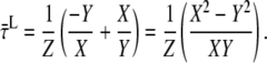
Next, the origin of the difference in average lifetime is addressed. In fluorescent systems containing a photosynthetic trap, the average fluorescence lifetime is the sum of two terms:  where
where  is the average charge separation time of a photosynthetic system in which the excitations are equilibrated over all the pigments according to the Boltzmann distribution and
  is the average time it takes for an excitation to reach the primary electron donor in the RC from an arbitrary pigment of the system, also called the first passage time (49,50).
  is independent of which pigment is initially excited. Therefore,
  must be different after core (
 ) or LHCI (
 ) excitation. For further interpretation, we introduce a simple model of two interacting clusters/compartments of pigments, core and LHCI (see Fig. 6). The equilibration within a cluster or compartment is assumed to be much faster than the transfer between the clusters. Within the context of this model, the rate of excitation transfer from LHCI to core (kLC) is given by (derivation in Appendix A)
 |
so the difference between the migration time after core and that after LHCI excitation ( ) equals the difference between average fluorescence lifetimes after core or LHCI excitation (
 ), which in turn is equal to the inverse (average) rate of energy transfer from LHCI to core (kLC)−1: 9.4 ± 4.9 ps.
FIGURE 6.

Model used for interpretation of fluorescence kinetics after (hypothetical) excitation of only core or only LHCI pigments. Excited-state energy can be transferred from core to LHCI and vice versa, and can be “trapped” by core (via charge separation) and LHCI (via fluorescence, intersystem crossing, and internal conversion) with rates ktrapC and ktrapL, respectively. Equilibration within the core and within LHCI is assumed to occur much faster than transfer between the two compartments. The value of ktrapL is neglected, because it is two orders of magnitude smaller than ktrapC.
The model in Fig. 6 permits the calculation of DAS after selective excitation of core or LHCI, analogous to the calculation of  and
and 
 |
 |
The total area of  and the total area of
  are normalized. The resulting DAS are given in Fig. 7. Again, the main difference is observed for the fastest DAS (24 ps). After core excitation, this resembles the fluorescence emission spectrum of PSI core particles, whereas after LHCI excitation it seems to be a mixture of the spectra of PSI core and LHCI particles. The spectral shapes and relative intensities of the other DAS are very similar for core and LHCI excitation, indicating that after the initial decay of 24 ps, the fluorescence decay kinetics no longer depend on the location of the initial excitation.
FIGURE 7.

Decay associated spectra of PSI-LHCI in solution at 287 K, after (hypothetical) excitation of only core or only LHCI pigments (dashed lines). DAS were calculated from linear combinations of the DAS in Fig. 3, with 65% core excitation at 410 nm, and 30% at 475 nm. See text for more details. In Fig. S12 (Data S1), the three slow DAS are presented after scaling to equal area.
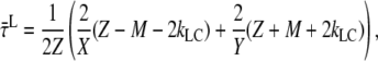
For the model in Fig. 6, it can be derived (Appendix A) that
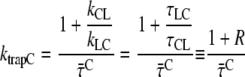 |
 |
The trapping rate, ktrapC, for excitations in the core can now be estimated from  and R. The ratio R is defined as R(λ) = kCL(λ)/kLC(λ) and it can be approximated as the ratio of the absorption spectra of core and LHCI (see Appendix A). Next, R(λ) is calculated using the value of
  (calculated from the DAS in Fig. 7) and varying the value of ktrapC until optimal agreement was obtained with the value of R(λ) calculated from the spectra (see Fig. 8). This leads to an estimated value of ktrapC = (22.5 ± 2.5 ps)−1, in good agreement with values obtained previously on isolated PSI core particles (e.g., (22,24,25).). Note that R(λ) as determined from the ratio of the absorption spectra should be somewhat red-shifted (see Appendix A) for a direct comparison with R(λ) determined from the fluorescence kinetics, because of the Stokes shift. However, as can be seen from Fig. 8, shifting the curve somewhat to the red does not alter the conclusion that ktrapC = (22.5 ± 2.5 ps)−1. It is worthwhile to note that no explicit red compartments are needed to describe the data. The red pigments are implicitly included in the compartments of core and LHCI and they contribute to the wavelength dependence of the parameter R.
FIGURE 8.

Ratio R = kCL/kLC calculated from the ratio between the absorption spectra of LHCI and core, and calculated from the average lifetime after selective excitation of core pigments ( ) and various rates of trapping from the core (ktrapC), using
 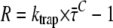 (see Discussion and Appendix A). R calculated by these two methods coincides rather well for ktrapC = (22.5 ± 2.5 ps)−1. This number was not affected by fixing the fastest lifetime to values ranging from 15 to 30 ps and reoptimizing the fit of the fluorescence decay traces.
In conclusion, the fluorescence decay kinetics of PSI-LHCI crystals are identical to those of PSI-LHCI in solution, obtained by solubilization of the crystals. Therefore, our results indicate that the PSI-LHCI conformation and dynamics in the crystal strongly resemble those in solution. Many previous fluorescence experiments on PSI-LHCI in solution differ from the PSI-LHCI crystal data, possibly because of sample heterogeneity, which is much smaller for solubilized crystals. Care should therefore be taken when relating those experiments to the crystal structure.
The fluorescence decay of PSI-LHCI in solution is faster after excitation at 410 nm than at 475 nm. This is caused by the time for energy transfer from LHCI to PSI core (∼9 ps). The initial DAS calculated for (hypothetical) excitation of only core pigments is blue-shifted relative to excitation of LHCI pigments. This illustrates the fact that excitations are not instantaneously distributed over the PSI-LHCI according to a Boltzmann distribution. The slower DAS are very similar for both excitation wavelengths, showing that after the initial 24 ps process, the fluorescence kinetics has become independent of the location of the initial excitation. The fluorescence kinetics of PSI-LHCI can be described with the simple model presented in Fig. 6, and the trapping rate for the equilibrated core is ktrap = (22.5 ± 2.5 ps)−1. The presence of LHCI leads to a slowing down of the overall trapping rate. The wavelength dependence of this overall trapping rate can be explained entirely by rapid equilibration within both core and LHCI followed by wavelength-dependent energy transfer between them. The wavelength dependence then stems from the wavelength dependence of the ratio R = kLC/kCL of the energy transfer rates from core to LHCI (kLC) and vice versa (kCL), and R is simply equal to the ratio of the number of pigments with energy hc/λ in core and LHCI, respectively, which is in good approximation equal to the ratio of the respective absorption spectra (see Appendix A). This model, much simpler than currently available models comprising more compartments with spectral forms that cannot be attributed to specific pigments or complexes within the supercomplex, can therefore serve as a starting point for detailed modeling at the molecular level, making use of the PSI-LHCI crystal structure.
SUPPLEMENTARY MATERIAL
To view all of the supplemental files associated with this article, visit www.biophysj.org.
Supplementary Material
Acknowledgments
This work is part of the research program of the Stichting voor Fundamenteel onderzoek der Materie (FOM), which is financially supported by the Nederlandse Organisatie voor Wetenschappelijk Onderzoek (NWO). B.v.O. was supported by FOM. N.N. acknowledges support from the Israel Science Foundation (grant 356/06). R. C. acknowledges support from “NWO, Earth and Life Science (ALW)”, through a VIDI grant.
APPENDIX A: DERIVATION OF EQUATIONS DESCRIBING ENERGY TRANSFER AND TRAPPING FOR THE MODEL IN FIG. 6
The time dependence of the probabilities C and L that the core or LHCI, respectively, are excited is described by two differential equations and two boundary conditions:
 |
(A1) |
 |
(A2) |
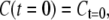 |
(A3) |
and
 |
(A4) |
These equations lead to expressions for C(t) and L(t):
 |
(A5) |
and
 |
(A6) |
with
 |
(A7) |
 |
(A8) |
 |
(A9) |
and
 |
(A10) |
Thus, C and L decay (and possibly rise) biexponentially with lifetimes τ1 and τ2 and amplitudes  The average fluorescence lifetimes after excitation of only core (
 ) or only LHCI (
 ) correspond to
 |
(A11) |
and
 |
(A12) |
Assuming that  (no direct decay from LHCI), and combining the equations above, using
  and
and  and
and  (when
(when  ) leads to
 |
(A13) |
and
 |
(A14) |
so that
 |
(A15) |
which simplifies further, using 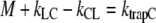 (see above), into
 |
(A16) |
Using  and
and 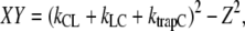 it then follows that
 |
(A17) |
i.e.,
 |
(A18) |
When, at excitation wavelength P, a fraction, p, of the excitations is created in the core, and at wavelength Q fraction q, then (see Discussion)
 |
(A19) |
and
 |
(A20) |
Introducing these equations into Eq. A18 gives a new expression for 
 |
(A21) |
Using 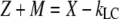 and
and  Eq. A14 can be rewritten as
 |
(A22) |
which simplifies into
 |
(A23) |
Substitution of Eqs. A7–A9 into A23 then gives
 |
(A24) |
This can be rewritten, by defining the ratio  so
so 
 |
(A25) |
Thus,
 |
(A26) |
and
 |
(A27) |
In other words,
 |
(A28) |
Note that the trapping time of the core is on the order of tens of picoseconds, and the lifetime of LHCI is on the order of nanoseconds, so the assumption that  is justified. Moreover, in this compartmental model, it is assumed that equilibration in a compartment is much faster than the transfer between compartments. Note that R, kCL, and kLC can be wavelength-dependent (see below). In addition, the overall decay can be described as
  (see Discussion) and
  is independent of which pigment is initially excited. Therefore, the different average lifetimes after excitation of either core or LHCI must be caused by variation of
  so
so
 |
(A29) |
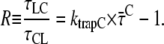
R(λ) can be calculated from independent experiments because it should obey the detailed balance equation for the above model:
 |
(A30) |
where nL and nC are degeneracy factors for LHCI and core, respectively. In this specific case, nL and nC depend on wavelength: nL and nC are the number of pigments of excited-state energy, EL and EC responsible for the fluorescence at wavelength λ. ΔE is the energy difference between the relevant pigments of core and LHCI at this wavelength (ΔE = EL − EC), which equals zero when measuring at one particular wavelength. This leads to
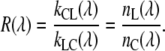 |
(A31) |
The ratio nL(λ)/nC(λ) can be approximated by the ratio of the absorption spectra (51) of LHCI and core, normalized to the number of Chls (AbsL,C) (see Appendix B) when the Stokes shift is neglected. Thus, the ratio of the absorption spectra of LHCI and PSI core (normalized to their pigment contents) provide the ratio of forward and backward energy transfer between core and LCHI. At wavelengths above ∼730 nm, the absorption of the core becomes very small and the accuracy of R decreases. It should be noted that it might be better to take the steady-state fluorescence spectra to obtain R, because the fluorescence, and not the absorption, is being probed but in that case, proper normalization of the spectra is difficult because of the trapping process and possible additional fluorescence-quenching mechanisms that can influence the ratio of the fluorescence spectra. Taking the absorption spectra instead leads to a small blue shift of R(λ). However, as can be seen in Fig. 8, this does not seriously affect the modeling results and the conclusion. It should be noted that the rates are wavelength-dependent, and therefore, it is expected that different lifetimes are observed at different wavelengths. Therefore, strictly speaking, the use of DAS is not allowed, because this assumes the presence of the same decay times at different wavelengths. However, the spectra and the corresponding lifetimes describe the data well, and here they are only used to obtain the various average lifetimes at different wavelengths that are used for the modeling.
APPENDIX B: ABSORPTION SPECTRA OF PSI-LHCI, PSI CORE, AND LHCI
Absorption spectra of PSI core and LHCI are necessary to determine the selective excitation of core and LHCI pigments at various wavelengths, and to determine the ratio, R, for forward and backward energy transfer between core and LHCI pigments. We recorded absorption spectra of PSI core, LHCI, and PSI-LHCI supercomplex. Samples were purified as described previously (52), and absorption spectra were recorded at 290 K using an SLM-Aminco DK2000 spectrophotometer. The results are shown in Fig. 9
FIGURE 9.

Absorption spectra of PSI-LHCI, PSI core, and LHCI, scaled to the number of pigments. The sum of core and LHCI spectra is also shown.
Editor: Alberto Diaspro.
References
- 1.Amunts, A., O. Drory, and N. Nelson. 2007. The structure of a plant photosystem I supercomplex at 3.4 Å resolution. Nature. 447:58–63. [DOI] [PubMed] [Google Scholar]
- 2.Ben-Shem, A., F. Frolow, and N. Nelson. 2003. Crystal structure of plant photosystem I. Nature. 426:630–635. [DOI] [PubMed] [Google Scholar]
- 3.Jordan, P., P. Fromme, H. T. Witt, O. Klukas, W. Saenger, and N. Krauss. 2001. Three-dimensional structure of cyanobacterial photosystem I at 2.5 Å resolution. Nature. 411:909–917. [DOI] [PubMed] [Google Scholar]
- 4.Jensen, P. E., R. Bassi, E. J. Boekema, J. P. Dekker, S. Jansson, D. Leister, C. Robinson, and H. V. Scheller. 2007. Structure, function and regulation of plant photosystem I. Biochim. Biophys. Acta. 1767:335–352. [DOI] [PubMed] [Google Scholar]
- 5.Castelletti, S., T. Morosinotto, B. Robert, S. Caffarri, R. Bassi, and R. Croce. 2003. Recombinant Lhca2 and Lhca3 subunits of the photosystem I antenna system. Biochemistry. 42:4226–4234. [DOI] [PubMed] [Google Scholar]
- 6.Croce, R., T. Morosinotto, S. Castelletti, J. Breton, and R. Bassi. 2002. The Lhca antenna complexes of higher plants photosystem I. Biochim. Biophys. Acta. 1556:29–40. [DOI] [PubMed] [Google Scholar]
- 7.Boekema, E. J., P. E. Jensen, E. Schlodder, J. F. L. van Breemen, H. van Roon, H. V. Scheller, and J. P. Dekker. 2001. Green plant photosystem I binds light-harvesting complex I on one side of the complex. Biochemistry. 40:1029–1036. [DOI] [PubMed] [Google Scholar]
- 8.Ihalainen, J. A., F. Klimmek, U. Ganeteg, I. H. M. van Stokkum, R. van Grondelle, S. Jansson, and J. P. Dekker. 2005. Excitation energy trapping in photosystem I complexes depleted in Lhca1 and Lhca4. FEBS Lett. 579:4787–4791. [DOI] [PubMed] [Google Scholar]
- 9.Şener, M. K., C. Jolley, A. Ben-Shem, P. Fromme, N. Nelson, R. Croce, and K. Schulten. 2005. Comparison of the light-harvesting networks of plant and cyanobacterial photosystem I. Biophys. J. 89:1630–1642. [DOI] [PMC free article] [PubMed] [Google Scholar]
- 10.Nelson, N., and C. F. Yocum. 2006. Structure and function of photosystems I and II. Annu. Rev. Plant Biol. 57:521–565. [DOI] [PubMed] [Google Scholar]
- 11.Fromme, P., E. Schlodder, and S. Jansson. 2003. Structure and function of the antenna system in photosystem I. In Light-Harvesting Antennas in Photosynthesis. B. R. Green and W. W. Parson, editors. Kluwer Academic. Dordrecht. 253–279.
- 12.van Amerongen, H., and J. P. Dekker. 2003. Light-harvesting in photosystem II. In Light-Harvesting Antennas in Photosynthesis. B. R. Green and W. W. Parson, editors. Kluwer Academic. Dordrecht. 219–251.
- 13.Gobets, B., and R. van Grondelle. 2001. Energy transfer and trapping in photosystem I. Biochim. Biophys. Acta. 1507:80–99. [DOI] [PubMed] [Google Scholar]
- 14.Gobets, B., H. van Amerongen, R. Monshouwer, J. Kruip, M. Rögner, R. van Grondelle, and J. P. Dekker. 1994. Polarized site-selected fluorescence spectroscopy of isolated Photosystem I particles. Biochim. Biophys. Acta. 1188:75–85. [Google Scholar]
- 15.Croce, R., A. Chojnicka, T. Morosinotto, J. A. Ihalainen, F. van Mourik, J. P. Dekker, R. Bassi, and R. van Grondelle. 2007. The low-energy forms of photosystem I light-harvesting complexes: spectroscopic properties and pigment-pigment interaction characteristics. Biophys. J. 93:2418–2428. [DOI] [PMC free article] [PubMed] [Google Scholar]
- 16.Morosinotto, T., J. Breton, R. Bassi, and R. Croce. 2003. The nature of a chlorophyll Ligand in Lhca proteins determines the far red fluorescence emission typical of photosystem I. J. Biol. Chem. 278:49223–49229. [DOI] [PubMed] [Google Scholar]
- 17.Schmid, V. H. R., K. V. Cammarata, B. U. Bruns, and G. W. Schmidt. 1997. In vitro reconstitution of the photosystem I light-harvesting complex LHCI-730: heterodimerization is required for antenna pigment organization. Proc. Natl. Acad. Sci. USA. 94:7667–7672. [DOI] [PMC free article] [PubMed] [Google Scholar]
- 18.Jennings, R. C., G. Zucchelli, R. Croce, and F. M. Garlaschi. 2003. The photochemical trapping rate from red spectral states in PSI-LHCI is determined by thermal activation of energy transfer to bulk chlorophylls. Biochim. Biophys. Acta. 1557:91–98. [DOI] [PubMed] [Google Scholar]
- 19.Gobets, B., I. H. M. van Stokkum, F. van Mourik, J. P. Dekker, and R. van Grondelle. 2003. Excitation wavelength dependence of the fluorescence kinetics in photosystem I particles from Synechocystis PCC 6803 and Synechococcus elongatus. Biophys. J. 85:3883–3898. [DOI] [PMC free article] [PubMed] [Google Scholar]
- 20.Ihalainen, J. A., I. H. M. van Stokkum, K. Gibasiewicz, M. Germano, R. van Grondelle, and J. P. Dekker. 2005. Kinetics of excitation trapping in intact photosystem I of Chlamydomonas reinhardtii and Arabidopsis thaliana. Biochim. Biophys. Acta. 1706:267–275. [DOI] [PubMed] [Google Scholar]
- 21.Croce, R., D. Dorra, A. R. Holzwarth, and R. C. Jennings. 2000. Fluorescence decay and spectral evolution in intact photosystem I of higher plants. Biochemistry. 39:6341–6348. [DOI] [PubMed] [Google Scholar]
- 22.Engelmann, E., G. Zucchelli, A. P. Casazza, D. Brogioli, F. M. Garlaschi, and R. C. Jennings. 2006. Influence of the photosystem I-light harvesting complex I antenna domains on fluorescence decay. Biochemistry. 45:6947–6955. [DOI] [PubMed] [Google Scholar]
- 23.Ihalainen, J. A., P. E. Jensen, A. Haldrup, I. H. M. van Stokkum, R. van Grondelle, H. V. Scheller, and J. P. Dekker. 2002. Pigment organization and energy transfer dynamics in isolated photosystem I (PSI) complexes from Arabidopsis thaliana depleted of the PSI-G, PSI-K, PSI-L, or PSI-N subunit. Biophys. J. 83:2190–2201. [DOI] [PMC free article] [PubMed] [Google Scholar]
- 24.Slavov, C., M. Ballottari, T. Morosinotto, R. Bassi, and A. R. Holzwarth. 2008. Trap-limited charge separation kinetics if photosystem I complexes from higher plant. Biophys. J. 94:3601–3612. [DOI] [PMC free article] [PubMed] [Google Scholar]
- 25.Turconi, S., N. Weber, G. Schweitzer, H. Strotmann, and A. R. Holzwarth. 1994. Energy transfer and charge separation kinetics in photosystem I. 2. Picosecond fluorescence study of various PS I particles and light-harvesting complex isolated from higher plants. Biochim. Biophys. Acta. 1187:324–334. [Google Scholar]
- 26.Melkozernov, A. N., J. Barber, and R. E. Blankenship. 2006. Light harvesting in photosystem I supercomplexes. Biochemistry. 45:331–345. [DOI] [PubMed] [Google Scholar]
- 27.Gobets, B., I. H. M. van Stokkum, M. Rogner, J. Kruip, E. Schlodder, N. V. Karapetyan, J. P. Dekker, and R. van Grondelle. 2001. Time-resolved fluorescence emission measurements of photosystem I particles of various cyanobacteria: a unified compartmental model. Biophys. J. 81:407–424. [DOI] [PMC free article] [PubMed] [Google Scholar]
- 28.Yang, M., A. Damjanovic, H. M. Vaswani, and G. R. Fleming. 2003. Energy transfer in photosystem I of cyanobacteria Synechococcus elongatus: model study with structure-based semi-empirical Hamiltonian and experimental spectral density. Biophys. J. 85:140–158. [DOI] [PMC free article] [PubMed] [Google Scholar]
- 29.Brüggemann, B., K. Sznee, V. Novoderezhkin, R. van Grondelle, and V. May. 2004. From structure to dynamics: modeling exciton dynamics in the photosynthetic antenna PS1. J. Phys. Chem. B. 108:13536–13546. [Google Scholar]
- 30.Damjanovic, A., H. M. Vaswani, P. Fromme, and G. R. Fleming. 2002. Chlorophyll excitations in photosystem I of Synechococcus elongatus. J. Phys. Chem. B. 106:10251–10262. [Google Scholar]
- 31.Pascal, A. A., Z. F. Liu, K. Broess, B. van Oort, H. van Amerongen, C. Wang, P. Horton, B. Robert, W. R. Chang, and A. Ruban. 2005. Molecular basis of photoprotection and control of photosynthetic light-harvesting. Nature. 436:134–137. [DOI] [PubMed] [Google Scholar]
- 32.Amunts, A., A. Ben-Shem, and N. Nelson. 2005. Solving the structure of plant photosystem I: biochemistry is vital. Photochem. Photobiol. Sci. 4:1011–1015. [DOI] [PubMed] [Google Scholar]
- 33.Croce, R., G. Canino, F. Ros, and R. Bassi. 2002. Chromophore organization in the higher-plant photosystem II antenna protein CP26. Biochemistry. 41:7334–7343. [DOI] [PubMed] [Google Scholar]
- 34.Borst, J. W., M. A. Hink, A. van Hoek, and A. J. W. G. Visser. 2005. Effects of refractive index and viscosity on fluorescence and anisotropy decays of enhanced cyan and yellow fluorescent proteins. J. Fluoresc. 15:153–160. [DOI] [PubMed] [Google Scholar]
- 35.van Hoek, A., and A. J. W. G. Visser. 1985. Artefact and distortion sources in time correlated single photon counting. Anal. Instrum. 14:359–378. [Google Scholar]
- 36.Digris, A. V., V. V. Skakoun, E. G. Novikov, A. van Hoek, A. Claiborne, and A. J. W. G. Visser. 1999. Thermal stability of a flavoprotein assessed from associative analysis of polarized time-resolved fluorescence spectroscopy. Eur. Biophys. J. 28:526–531. [DOI] [PubMed] [Google Scholar]
- 37.Boens, N., M. Ameloot, I. Yamazaki, and F. C. De Schryver. 1988. On the use and the performance of the delta function convolution method for the estimation of fluorescence decay parameters. Chem. Phys. 121:73–86. [Google Scholar]
- 38.Russinova, E., J.-W. Borst, M. Kwaaitaal, A. Cano-Delgado, Y. Yin, J. Chory, and S. C. de Vries. 2004. Heterodimerization and endocytosis of Arabidopsis brassinosteroid receptors BRI1 and AtSERK3 (BAK1). Plant Cell. 16:3216–3229. [DOI] [PMC free article] [PubMed] [Google Scholar]
- 39.van Oort, B., S. Murali, E. Wientjes, R. B. M. Koehorst, R. Spruijt, A. van Hoek, R. Croce, and H. van Amerongen. 2008. Ultrafast resonance energy transfer from a site-specifically attached fluorescent chromophore reveals the folding of the N-terminal domain of CP29. Chem. Phys. In press.
- 40.van Stokkum, I. H. M., D. S. Larsen, and R. van Grondelle. 2004. Global and target analysis of time-resolved spectra. Biochim. Biophys. Acta. 1657:82–104. [DOI] [PubMed] [Google Scholar]
- 41.Eske, A. T., and R. K. Naqvi. 1979. Viscosity dependence of the fluorescence lifetimes of cryptocyanine, pinacyanol and DDI. Chem. Phys. Lett. 63:128–132. [Google Scholar]
- 42.Mialocq, J. C. 1982. Picosecond study of pinacyanol photophysics. Chem. Phys. 73:107–115. [Google Scholar]
- 43.Mialocq, J. C., J. Jaraudias, and P. Goujon. 1977. Picosecond spectroscopy of pinacyanol (1,1‘-diethyl—2,2’-monocarbocyanine chloride). Chem. Phys. Lett. 47:123–126. [Google Scholar]
- 44.Sundstrom, V., and T. Gillbro. 1981. Viscosity dependent radiationless relaxation rate of cyanine dyes. A picosecond laser spectroscopy study. Chem. Phys. 61:257–269. [Google Scholar]
- 45.Voigt, G., F. Nowak, J. Ehlert, W. J. D. Beenken, D. Leupold, and W. Sandner. 1997. Substructures and different energy relaxation time within the first electronic transition of pinacyanol. Chem. Phys. Lett. 278:380–390. [Google Scholar]
- 46.Thistlethwaite, P. J., and H. J. Griesser. 1982. The temperature dependence of the fluorescence lifetime of pinacyanol iodide. Chem. Phys. Lett. 91:58–62. [Google Scholar]
- 47.de Weerd, F. L., J. T. M. Kennis, J. P. Dekker, and R. van Grondelle. 2003. β-Carotene to chlorophyll singlet energy transfer in the photosystem I core of Synechococcus elongatus proceeds via the β-carotene S-2 and S-1 states. J. Phys. Chem. B. 107:5995–6002. [Google Scholar]
- 48.Leupold, D., K. Teuchner, J. Ehlert, K.-D. Irrgang, G. Renger, and H. Lokstein. 2002. Two-photon excited fluorescence from higher electronic states of chlorophylls in photosynthetic antenna complexes: a new approach to detect strong excitonic chlorophyll a/b coupling. Biophys. J. 82:1580–1585. [DOI] [PMC free article] [PubMed] [Google Scholar]
- 49.van Amerongen, H., L. Valkunas, and R. van Grondelle. 2000. Photosynthetic Excitons. World Scientific, Singapore.
- 50.Broess, K., G. Trinkunas, C. D. van der Weij-de Wit, J. P. Dekker, A. van Hoek, and H. van Amerongen. 2006. Excitation energy transfer and charge separation in photosystem II membranes revisited. Biophys. J. 91:3776–3786. [DOI] [PMC free article] [PubMed] [Google Scholar]
- 51.Laible, P. D., R. S. Knox, and T. G. Owens. 1998. Detailed balance in Förster-Dexter excitation transfer and its application to photosynthesis. J. Phys. Chem. B. 102:1641–1648. [Google Scholar]
- 52.Croce, R., G. Zucchelli, F. M. Garlaschi, and R. C. Jennings. 1998. A thermal broadening study of the antenna chlorophylls in PSI-200, LHCI, and PSI core. Biochemistry. 37:17355–17360. [DOI] [PubMed] [Google Scholar]
Associated Data
This section collects any data citations, data availability statements, or supplementary materials included in this article.