Abstract
In many micromachined sensors the thin (2–10 μm thick) air film between a compliant diaphragm and backplate electrode plays a dominant role in shaping both the dynamic and thermal noise characteristics of the device. Silicon microphone structures used in grating-based optical-interference microphones have recently been introduced that employ backplates with minimal area to achieve low damping and low thermal noise levels. Finite-element based modeling procedures based on 2-D discretization of the governing Reynolds equation are ideally suited for studying thin-film dynamics in such structures which utilize relatively complex backplate geometries. In this paper, the dynamic properties of both the diaphragm and thin air film are studied using a modal projection procedure in a commonly used finite element software and the results are used to simulate the dynamic frequency response of the coupled structure to internally generated electrostatic actuation pressure. The model is also extended to simulate thermal mechanical noise spectra of these advanced sensing structures. In all cases simulations are compared with measured data and show excellent agreement—demonstrating 0.8 pN/√Hz and 1.8 μPa/√Hz thermal force and thermal pressure noise levels, respectively, for the 1.5 mm diameter structures under study which have a fundamental diaphragm resonance-limited bandwidth near 20 kHz.
Index Terms: Finite elements, MEMS, microphone, thermal mechanical noise
I. Introduction
ACCURATE modeling of damping is important for many micromachined structures. In addition to affecting device dynamics, the degree of damping in any system directly influences thermal mechanical noise levels, or Brownian motion, as is made clear by the generalized Nyquist relation [1]. In many microfabricated sensors operated in atmospheric environments, the dominant damping mechanism is viscous shearing (and at high frequencies—compression) of a thin air film between two planar structures moving normal to each other—commonly referred to as squeeze-film damping. Bao and Yang [2] have recently provided a review of squeeze-film damping in MEMS—summarizing modeling efforts and the influence of film dynamics on the overall dynamic response of vibrating systems. Gabrielson [3] has summarized the particular importance of the relationship between thin-film damping and thermal noise levels in micromachined sensors, most notably capacitive-based microphone structures which consist of a compliant diaphragm vibrating in close proximity (2–10 μm) to a rigid backplate electrode. In these cases, damping (and thermal-mechanical noise) is reduced by a repetitive pattern of small holes or perforations in the microphone backplate designed to alleviate pressure build-up in the thin air film. The degree to which the structure can be perforated (i.e., the ratio of open-area to total area) is limited in condenser MEMS microphones by total capacitance requirements. This design compromise—across mechanical and electrical domains—ultimately limits the sensor’s detection performance.
The squeeze film damping dynamics in microphone structures are captured by the Reynolds squeeze film equation. Analytical solutions and approximations exist for relatively simple geometries and have proven useful in modeling traditional perforated plate structures employed in capacitive microphones [3]–[6]. Recently, micromachined microphones with integrated optical interferometric readout have been introduced [7], [8]. These structures have minimal capacitance design requirements and utilize backplate architectures with minimal area (i.e., large perforations) to achieve low damping, broadband frequency response, and low thermal mechanical noise levels. Thin-film damping in these structures is not easily studied with analytical approximations due to relatively complex backplate geometries. Finite-element models based on discretization of the 2-D Reynolds equation have been introduced [9], [10] enabling rigorous analysis and design of such structures. A reduced-order modeling procedure introduced by Mehner et al. [11] is particularly well-suited for simulating squeeze film dynamics in the advanced micromachined microphone structures under consideration. With this approach, the pressure in the thin air film is simulated in response to vibratory modal displacement profiles of the microphone diaphragm and the results are used to compute the corresponding modal damping coefficients. The resulting modal equations can be used to simulate the dynamic system (i.e., diaphragm and coupled air-film) response to any arbitrary-shaped external forcing input across any frequency range.
In the following, we briefly summarize the silicon microphone structure under study and review the modeling procedure which is implemented here using an automated macro in ANSYS [12]. The dynamic response of the diaphragm structure to internally generated electrostatic actuation pressure is simulated and compared with measurements. This is first performed in a vacuum environment which enables study of the diaphragm dynamics without complexities introduced by the air film. Simulations and measurements in air are performed for two different device structures with different gap thickness, and results are in excellent agreement in both cases. A unique contribution of this paper is the extension of the modal projection procedure to model and simulate thermal mechanical noise spectra of micromachined sensors. Simulated and measured noise spectra are presented and are in good agreement, demonstrating a thermal displacement noise level of 40 fm/√Hz and corresponding thermal pressure and force noise levels of 1.82 μPa/√Hz and 0.8 pN/√Hz, respectively, for these advanced micromachined sensing structures.
II. Microfabricated Silicon Structures
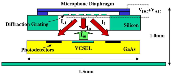
A fully integrated embodiment of the overall sensor technology is summarized schematically in Fig. 1. In this approach, which has been analyzed in detail previously [7], a monolithically integrated diffraction grating serves as the beam splitter in a Michelson-type interferometer, and the intensities of a zero and higher order diffraction orders are modulated by the diaphragm vibration. The integration embodiment summarized in Fig. 1 has recently been demonstrated with vertical cavity surface emitting lasers and photodetection electronics integrated into sub-1 mm3 volumes [13]. As also noted in Fig. 1, the diaphragm and grating backplate are made electrically conductive which enables the application of precisely controlled broadband electrostatic forces to the diaphragm structure—a feature used in this paper for self-characterization of the film-coupled diaphragm dynamics.
Fig. 1.
Schematic of an integrated diffraction-based optical microphone (borrowed from J. Acoust. Soc. Amer., Vol. 122, No. 4, October 2007).
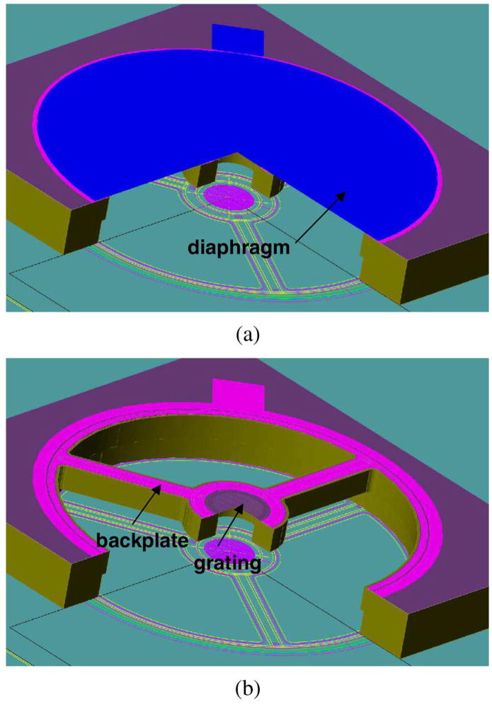
A recent embodiment of the silicon structure from Fig. 1 is summarized by the 3-D computer-aided design (CAD) cross section presented in Fig. 2(a) [8]. A 1.5 mm diameter, 2.25 μm thick polysilicon diaphragm with near-zero residual stress is surface-micromachined on a silicon substrate with a captured-oxide anchor to provide a clamped boundary condition along the circumference. The bulk silicon beneath the diaphragm is Bosch-etched to create a backplate in the form of three rigid armlike structures which hold a 200 μm diameter surface micromachined diffraction-grating rigidly in place beneath the diaphragm. A thin 0.3 μm polysilicon layer exists atop the three-arm backplate to form the ground electrode for electrostatic actuation, with the diaphragm itself serving as the top electrode. The CAD cross section in Fig. 2(a) has been repeated in Fig. 2(b) with the diaphragm removed to show the details of the underlying backplate structure. A micrograph of a fabricated structure taken from the backside is presented in Fig. 3 to aid in the visualization of these features. In contrast to traditional capacitive microphone backplates which consist of a plate with an array of small perforation holes, the backplate design summarized in Figs. 2 and 3 consists of mostly open area. The air-film under study occupies the thin gap between the three-arm backplate electrode and the diaphragm. This gap height is determined by the sacrificial oxide thickness used in the fabrication process and—in addition to perforation geometry—strongly affects damping levels. Structures with both 3 and 6 μm gaps have been simulated, fabricated, and experimentally tested.
Fig. 2.
Three-dimensional computer-generated cross sections of the silicon microphone structure showing (a) the microphone diaphragm and (b) diaphragm removed to show the details of the underlying backplate.
Fig. 3.
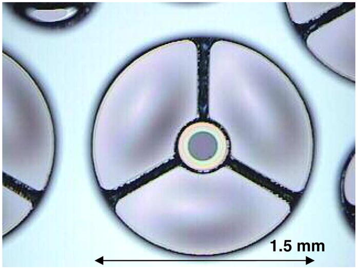
Micrograph of a fabricated microphone structure from the backside view showing the three-arm bulk-silicon backplate structure.
III. Model Overview
The analysis begins with extraction of the mass normalized mode shapes Φi and corresponding modal frequencies ωi of the microphone diaphragm in Fig. 2(a), without the presence of the fluid film. The mode shapes form the basis functions for a modal superposition according to
| (1) |
where δ is the distributed diaphragm displacement, xm are the scalar modal coordinates, and k is the number of modes retained in the superposition. In the modal coordinate description of the diaphragm displacement, the diaphragm dynamics are governed by a set of k uncoupled modal equations, each with a mass of unity, a stiffness of , and a modal excitation force of
| (2) |
where P is any distributed external pressure acting on the diaphragm and the integral is computed across the microphone diaphragm area [14].
Without loss of generality, the presence of the fluid film can be considered to introduce a damping matrix C into the dynamic modal equations with constitutive relation
| (3) |
In a frequency domain formulation of (3), the elements of C can be isolated and extracted individually via
| (4) |
through a modal projection procedure where: 1) the nth mode shape is applied to the fluid film with specific vibration amplitude Xn; 2) the resulting film pressure distribution Pn is solved for using a discretized 2-D version of the Reynolds equation; and 3) the modal force is computed by integrating the complex pressure distribution with the mth mode shape. The damping coefficients are generally complex and frequency dependent, as the film pressure has components in phase with the diaphragm velocity—representing the squeeze resistance, and components in phase with displacement—representing film stiffening. The preceding is a concise summary of a more detailed description provided by Mehner et al. [11] where the procedure was first introduced. In this paper, this portion of the model is constructed and executed in ANSYS, where a DMPEXT macro automates the system identification procedure outlined in (4). This finite-element implementation is ideal for studying the advanced backplate designs presented in Figs. 2(b) and 3 as discretization of the Reynolds’s equation permits studying complex film geometries with rigor and without approximation.
In this paper, a complete model of the microphone dynamics is executed via insertion of the C matrix into the system of k modal equations
| (5) |
with computation of the right-hand side of (5) [i.e., (2)] performed in ANSYS for any arbitrary-shaped forcing input and simultaneous solution of the matrix equation (5) performed in MATLAB [15]. Neglecting off-diagonal damping terms results in uncoupled modal equations with solution
| (6) |
where the damping ratio ζm = Re{Cm}/(2 * ωm) has been introduced as well as a film-stiffness ratio which characterizes the stiffness the film adds to the system in comparison to that of the diaphragm itself. Upon solution of (5) or (6), the modal displacements Xm are superimposed via (1) in MATLAB to simulate the distributed diaphragm displacement. Implementation of this procedure is made clear as the model is applied to simulate the dynamic response of the structure summarized in Figs. 2 and 3 to internally generated electrostatic actuation forces in both vacuum and air environments.
IV. Dynamic Response in Vacuum
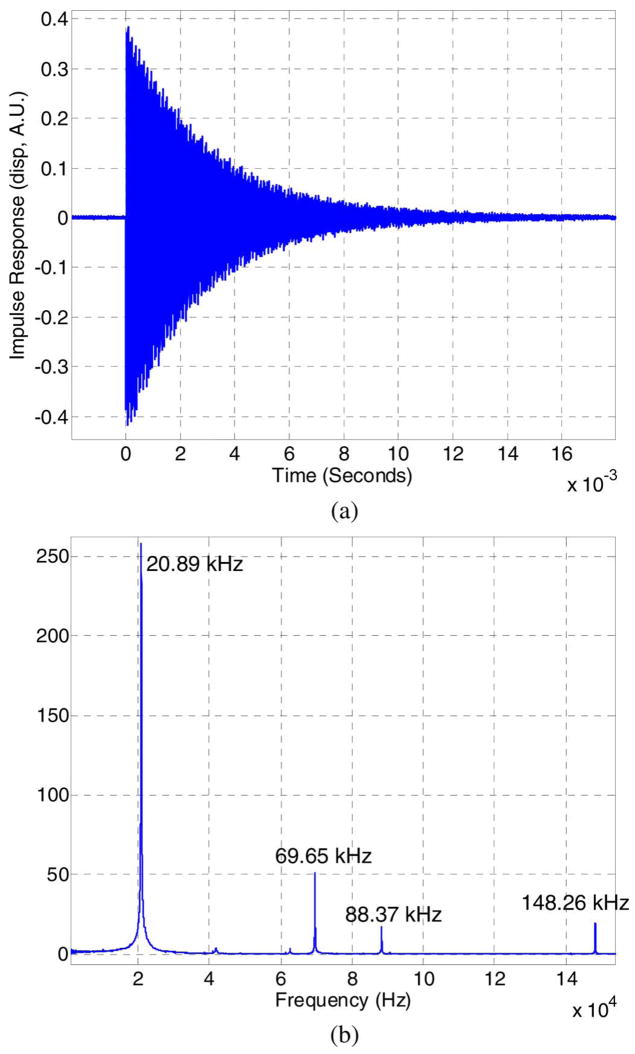
Measurements in vacuum reveal dynamic properties of the microphone diaphragm without complexities introduced by the squeeze-film, and experimental identification of modal resonant frequencies in vacuum validates the structural model of the diaphragm itself. The measured center diaphragm displacement of the 1.5 mm diameter device shown in Fig. 3 in response to a broadband electrostatically generated impulse pressure of 1-μs duration is presented in Fig. 4(a). In this experiment the silicon structure is placed in a vacuum chamber (~100 mtorr), and the light source and photodetection electronics represented by the bottom substrate in Fig. 1 are remotely positioned on the opposing side of a glass window. The photocurrent from a first diffracted order is measured to obtain the diaphragm displacement information. Details of this experimental configuration have been provided previously [8]. The fast Fourier transform (FFT) of the data in Fig. 4(a) provides the dynamic frequency response of this device and is presented in Fig. 4(b) where a fundamental resonance near 21 kHz is observed as well as several higher order resonances. Positioning of the fundamental diaphragm resonance above 20 kHz is ideal for realizing broadband acoustic sensing structures.
Fig. 4.
(a) Electrostatic impulse response of the microphone diaphragm displacement as measured optically in vacuum. (b) FFT of the impulse response (i.e., the dynamic frequency response of the device in vacuum).
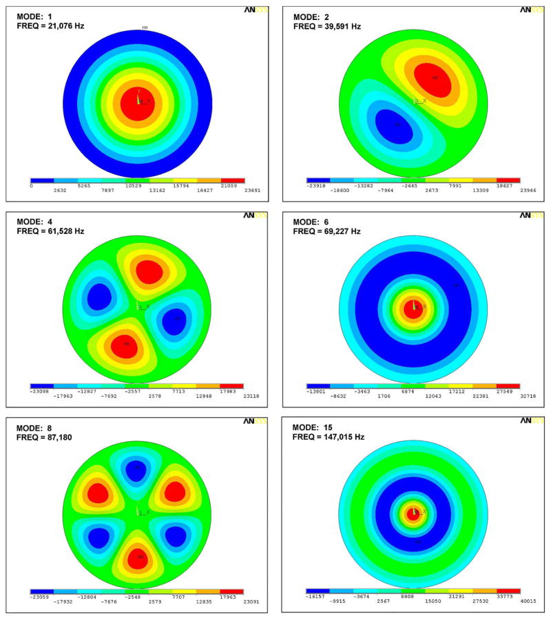
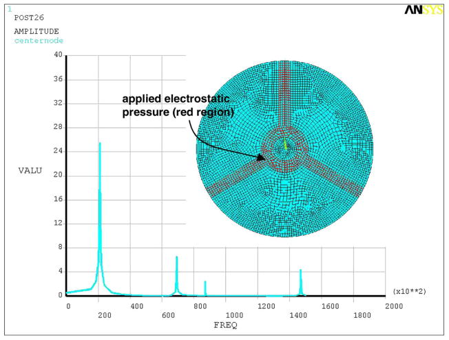
The diaphragm is modeled in ANSYS using SHELL61 elements with clamped boundary conditions and material properties for polysilicon that have been characterized in Sandia’s process technology (density—2330 kg/m3, Young’s modulus—160 GPa, Poisson’s ratio—0.23). The first eight mass normalized mode shapes and corresponding modal resonant frequencies extracted using ANSYS are presented in Fig. 5. Nonaxisymmetric modes (e.g., modes 2 and 3) occur in orthogonal pairs,1 with the pairs not shown in Fig. 5 for the sake of brevity. Mode 15, the third axisymmetric mode, is also shown. A small residual diaphragm tension is used as a single scalar parameter in the model to align the diaphragm’s modal resonant frequencies with the experimentally observed resonant frequencies in Fig. 4(b). Application of this technique reveals that the first four resonant frequencies observed in Fig. 4(b) are not those of the first four diaphragm modes, but rather those of modes 1, 6, 8, and 15, as exceptionally good agreement can be observed in the respective comparison between Figs. 4(b) and 5. All four modes are aligned to within a maximum deviation of 1.6%. The presence of only these modes in the response spectrum is expected as these are the only modes with significant modal excitation [i.e., a significant modal force Fm as defined in (2)]. This is rigorously demonstrated by applying the analysis outlined in (2) and (6), where the modal forces resulting from electrostatic excitation are computed using ANSYS and summarized in Table I. In addition to axisymmetric modes 1, 6, and 15, mode 8 shows significant excitation due to its strong resemblance to the electrostatic actuation electrode shape as can be observed by comparing Fig. 2(b) with the eighth mode shape in Fig. 5. All other diaphragm modes not represented in Table I have negligible excitation—at least two orders of magnitude below those represented in the table. The simulation result following application of (6) is presented in Fig. 6 and shows excellent agreement with the measured response in Fig. 4(b). The inset in Fig. 6 highlights the region of applied electrostatic pressure used in the computation of values presented in Table I and in the simulation.
Fig. 5.
Various mode shapes and corresponding modal resonant frequencies of the microphone diaphragm as simulated in ANSYS.
TABLE I.
Normalized Modal Forces for Electrostatic Excitation. All Other Modes Between 1 and 15 Have a Force Less Than 0.001 and Do Not Contribute to the Dynamic Response
| mode 1 | mode 6 | mode 8 | mode 15 | |
|---|---|---|---|---|
| normalized modal force | 1 | 0.38 | 0.6 | 0.32 |
Fig. 6.
Simulated dynamic frequency response of the diaphragm in vacuum to pressure generated electrostatically (the applied pressure region is highlighted in the inset).
It should be noted that although the precise center displacement of mode 8 is zero, the average modal displacement across the illuminated grating area [i.e., the 200 μm diameter region in Fig. 3(b)] is nonzero and has been used in the simulation, as this more accurately reflects the optical measurement. In addition, the damping mechanisms in vacuum have not been studied, so comparisons of ζms (or Qs) between Figs. 4(b) and 6 are not meaningful. The film stiffness ratios rm are set to zero in the vacuum simulation and small values of damping have been added simply for computational stability.
The results summarized in Fig. 6 and in Table I demonstrate another potentially useful feature of the model’s capabilities—the ability to accurately model the selective excitation of modes and therefore craft the dynamic frequency response of the device across a wide frequency range via design of the actuation electrode geometry. Although not particularly significant in this microphone application, this may be useful, for example, in the design of ultrasound transducers where a diaphragm’s higher-order modes are selectively detected [16].
V. Squeeze Film Simulations and Dynamic Response Measurements in Air
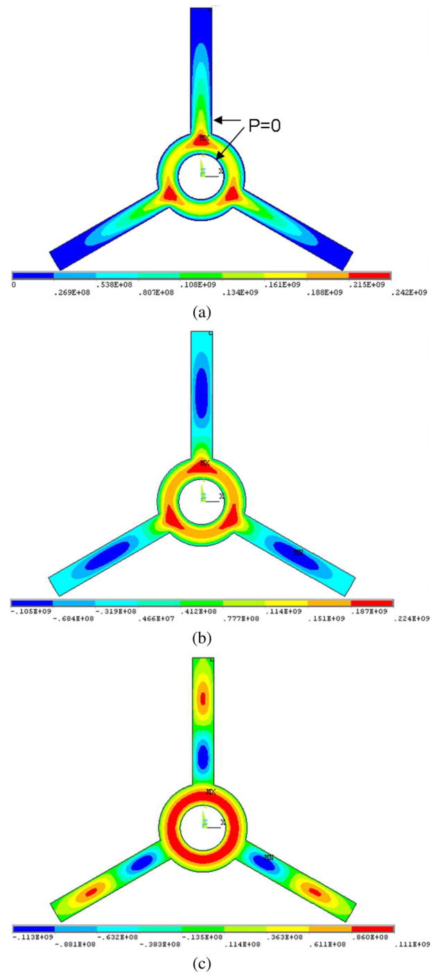
Extraction of the mass normalized mode shapes and corresponding modal frequencies of the diaphragm is a first step in performing the squeeze film damping analysis and simulating dynamic frequency response functions in air. Vertical displacement of the diaphragm squeezes the air film laterally toward the large open regions existing between the three-arm backplate structure with the creation of film pressure due to both viscous shearing and, at higher frequencies, film compression. This film region is modeled in ANSYS using 2-D Fluid 36 elements. The vibratory displacement profile of the mode under study is written as a boundary condition to the fluid in a harmonic response analysis, and the resulting film pressure is simulated across the frequency range of interest—20 Hz to 100 kHz in this case. Standard properties for air at atmosphere are used in all simulations (dynamic viscosity—18.3 μPa ·s, mean free path—64 nm) with the effective viscosity derived from the Knudsen number2 for the gap height [2]. Real components of the distributed film pressure for the first three axisymmetric mode shapes are presented in Fig. 7 following simulations where 1 nm/s peak modal velocity has been applied at 1 kHz to a structure with a 3 μm-gap. Regions of highest film pressure are observed at regions of highest displacement for the respective mode and at regions furthest away from the pressure-release boundaries where the film interfaces with the large open-air regions between the three-arm backplate structure and the grating region in the center [highlighted in Fig. 7(a)]. The grating region demands special attention and cannot be modeled with the approach presented here as the aspect ratio defining the lateral film width (i.e., 2 μm grating finger width) to film height (i.e., 3–6 μm) is not significantly greater than unity, a condition underlying applicability of the Reynolds squeeze film equation itself [2]. The fluid–grating interaction has been studied using a more general procedure and the results have been incorporated into the formulation presented here. For the 3 μm gap device currently under consideration, the grating region accounts for less than 5% of the total damping for any particular mode.
Fig. 7.
Simulated film pressure across the microphone diaphragm and backplate for the first three axisymmetric modal displacement profiles (units in nanopascal) following application of 1 nm/s peak modal velocity at 1 kHz.
It should also be noted that the film boundary condition at perforations in backplates is not in general a pressure release, but instead more accurately governed by an impedance condition created by viscous resistance along the vertical dimension of the perforation itself. The total resistance can be significant for traditional backplate structures employing arrays of small holes [5] but becomes small for large openings such as those employed in the structures presented here.
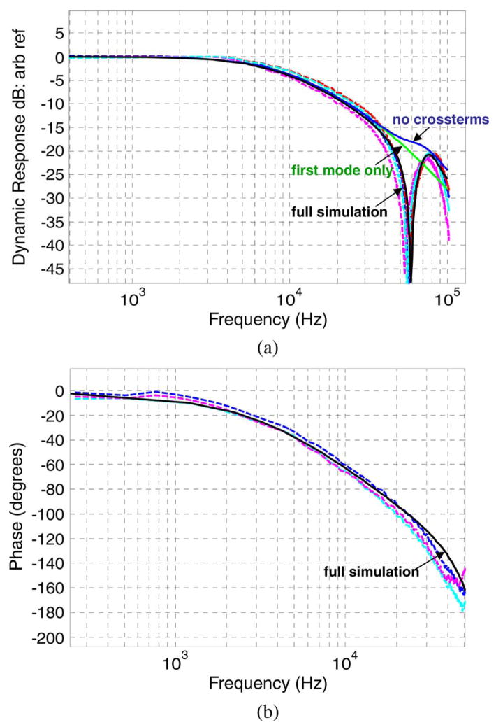
The pressure distributions presented in Fig. 7 are integrated to obtain the relevant modal forces which are then normalized to the input modal velocity to obtain the coefficients in the damping matrix as summarized in (4). The electrostatic modal excitation forces are the same as for the vacuum case summarized in Table I, with modes 1, 6, and 8 being the only modes expected to significantly shape the dynamics of the device. Dynamic frequency response measurements on several 3 μm gap microphone structures originating from the same process wafer are presented in Fig. 8(a) and (b), where the magnitude and phase responses, respectively, are presented in the dotted traces. Also shown as the solid trace labeled “full simulation” is the simulation result following (1) and (5), where in this case modes 1, 6, and 8 are retained in the modal superposition along with their modal damping coefficients C11, C66, and C88 and their respective cross-coupling terms C16, C18, and C68. The simulation includes no fitting parameters and is in exceptional agreement with the measured data—accurately predicting the roll-off in the amplitude response at approximately 8 kHz (3 dB-cut off frequency), the null in the response at 60 kHz, and the following peak in the response occurring near 80 kHz. Amplitude response simulations without inclusion of the cross damping terms and with inclusion of only the first modal equation are also presented and labeled in Fig. 8(a), where even the later simplest case is seen to accurately predict the device response up to 40 kHz. The fundamental resonant frequency (as determined with the vacuum measurement procedure summarized in Fig. 4) and simulated damping ratio ζ1 in this case are 21.1 kHz and 1.38, respectively.
Fig. 8.
Measured (a) amplitude and (b) phase components of the dynamic frequency response to electrostatic excitation for 1.5 mm diameter microphone structures with 3 μm squeeze film thickness (dotted traces) and corresponding simulation results (solid trace).
Physically, cross terms arise when excitation of the diaphragm near a mode creates a film pressure distribution that creates a force on another mode [11]. Accuracy beyond the fundamental resonant frequency and therefore inclusion of modes other than the fundamental in the response simulations is not critical or necessary for the particular microphone structures currently under study. Demonstration of the ability to accurately model the frequency response across several device modes may, however, be useful for advanced audio transducers such as recently developed biologically inspired microphones whose relevant operating frequency range (20 Hz–20 kHz) spans multiple structural modes of the diaphragm which are used to provide useful directional characteristics in the response [17], [18].
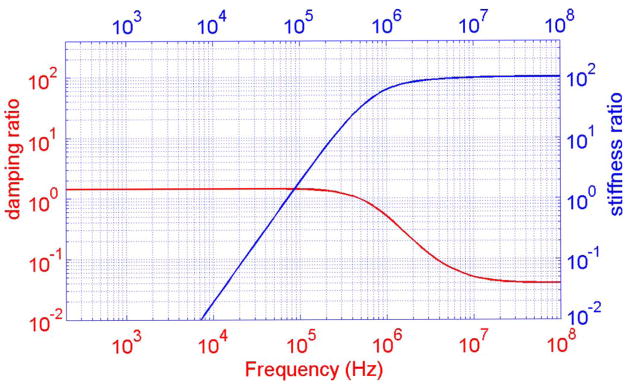
Stiffness properties of the film do not significantly influence the dynamic response of the structures under study. Fig. 9 presents the simulated values of ζ1 and r1 as a function of frequency for the 3 μm thick film. A transition frequency is typically defined at the 3 dB roll-off in damping—near 400 kHz in this case—and corresponds to the presence of significant film compression where viscous forces restrict the film from displacing laterally. In general, compression effects and film stiffening have the ability to affect the dynamic response of the device at much lower frequencies than the typically defined 3 dB cutoff. At r1 = 1, which occurs near 70 kHz in this case as observed in Fig. 9, the stiffness presented by the film becomes greater than that of the diaphragm. As is apparent from (5), the dynamic response of the structure is strongly affected in cases where this critical frequency is less than the diaphragm resonant frequency [2]. When this is not the case, film stiffening does not typically significantly influence the dynamic response of the structure as the response is dominated by the inertia of the diaphragm itself [i.e., the ω2 term in the denominator of (6)].
Fig. 9.
Simulated damping and film-stiffness ratios versus frequency for the 3μm gap microphone structure.
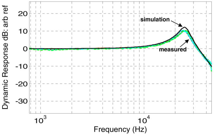
Measurements and simulations are also performed on 6 μm gap structures. Ten devices have been experimentally characterized and are presented in Fig. 10 in the colored traces. The simulation result presented in Fig. 10 contains only the first mode and again shows remarkable agreement with the measured data without the use of any fitting parameters. The fundamental resonant frequency and simulated damping ratio for this structure are 24.6 kHz and 0.135, respectively. For this structure, the grating region accounts for approximately 25% of the total damping. The difference in the grating’s contribution to total system damping for the 6 and 3 μm cases (i.e., 5% versus 25% contribution) is primarily caused by a relatively independent scaling of damping with gap height for the grating region. Film pressure across the backplate follows a 1/gap3 dependence consistent with the Reynolds formulation, whereas film pressure in the grating region displays only small dependence on gap height in the 3–6 μm range.
Fig. 10.
Measured electrostatic frequency response of ten different 1.5 mm diameter microphone structures with 6 μm gap height fabricated on the same silicon wafer (colored traces) and corresponding simulation (solid and labeled black trace).
VI. Thermal Noise Spectra Simulations and measurements
The benefit of accurately modeling thin-film damping and overall system dynamics in complex micromachined structures extends to accurately simulating thermal mechanical noise levels—a critical capability in the design of high fidelity sensing structures. Direct application of the generalized Nyquist relation
| (7) |
to the first modal equation of motion results in the thermal displacement noise (i.e., Brownian motion) spectra δtn of the microphone diaphragm
| (8) |
where k and T are Boltzmann’s constant and the ambient temperature, respectively. The denominator is recognized as the frequency domain transfer function for the fundamental mode, where only the absolute value is relevant due to the random nature of the thermal noise excitation. Simulation of thermal noise spectra across several device modes is performed by simply summing the displacement contributions from each mode incoherently (i.e., ). This formulation has proven useful, for example, in studying thermal noise spectra of multimode cantilever structures used in atomic force microscopy (AFM) [19]. For the microphone structures currently under investigation in this paper, retention of only the first mode contribution is expected to provide an accurate approximation over the frequency range of interest as is the case for the dynamic response simulations presented in Figs. 8 and 10. Generally speaking, simulation results utilizing (8) are expected to exhibit a high degree of accuracy as the fundamental resonant frequency can be precisely extracted via vacuum measurements as demonstrated here, and the computation of Φ depends solely on the geometric dimensions of the diaphragm and the material density (i.e., polysilicon in this case)—both of which are known to a high degree of accuracy. In the design phase, the damping ratio can be directly simulated as summarized in this paper. Alternatively, for existing structures, the damping ratio can be experimentally extracted from dynamic response measurements such as those presented in Figs. 8 and 10 [8].
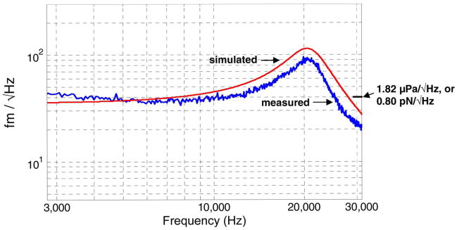
The measured thermal displacement noise spectrum of a 1.5-mm diameter microphone structure with a 6 μm gap height is presented in Fig. 11. The measurement is performed in an anechoic testing facility3 using the optical readout features of the detection technology summarized in Fig. 1, with the displacement detection sensitivity first calibrated using internal actuation features of the device—a procedure summarized in more detail previously [8]. The simulation following (8) is also presented using a fundamental resonant frequency of 21.0 kHz and the simulated damping ratio equal to 0.157. The slight difference in damping ratio in this simulation as compared to that presented in Fig. 10 is due to the small difference in resonant frequency (i.e., the simulated damping coefficient C11 which depends only on the properties of the film is the same in both cases). Here again, the simulated spectra is in good agreement with the measurement—predicting the absolute thermal displacement noise level within 2 dB maximum deviation across the frequency range presented.
Fig. 11.
Measured and simulated thermal displacement noise spectra for a 6 μm gap structure.
Careful attention has been given to the measurement in Fig. 11 to ensure the displacement resolving capability of the optical readout system is below that of the thermal mechanical noise of the diaphragm in the 5–30 kHz range, which is sufficient for studying the thermal noise profile. Generally speaking, the displacement resolving capability is limited by quantum shot noise at the photodetectors and small intensity fluctuations of the semiconductor laser [8]. The effects of the latter are responsible for the slight increase in the measured spectra near 5 kHz. In an actual sensor implementation, efforts should be made to cancel laser intensity noise across all frequencies of interest [20].
The 40 fm/√Hz measured displacement level can be referred to force and pressure inputs via the finite-element model of the diaphragm or direct measurement. For example, the displacement of the diaphragm resulting from a concentrated force load at its center is modeled as 49.8 mm/N for the structure in Fig. 11 (i.e., stiffness of 20.1 N/m), which results in an input referred thermal force noise level of 0.8 pN/√Hz as labeled in the figure. Modeled diaphragm compliance values have proven to be within 10% of directly measured values using calibrated AFM cantilevers. Similarly, the pressure sensitivity of this structure is simulated as 22 nm/Pa which results in 1.82 μPa/√Hz input referred thermal pressure noise, also directly labeled on Fig. 11.
VII. Discussion and Conclusion
The potential impact of the high pressure resolution for the microphone application under development can be highlighted with reference to an A-weighted self-noise4 which is approximately 21 dB(A) for the thermal pressure noise level demonstrated here. Achieving this figure from a 1.5-mm diameter diaphragm structure with 20 kHz bandwidth is a notable accomplishment, as MEMS microphone structures of comparable size typically have thermal noise levels at least 10 dB higher and/or 1/2 this bandwidth [3], [21], [22]. The versatile device model and simulations presented here have played an important role in realizing this performance. Sub-pN force resolution and large bandwidth are also ideal for a recently demonstrated new AFM probe technology with similar device structure [23]. The demonstrated microstructure and the accompanying device model may be useful for these applications as well.
In future designs, thin-film damping simulations will aid in making continued performance and fabrication-design improvements. Rigorous characterization of the displacement resolving capabilities of the approach (which takes into account noise in the readout electronics and quantum shot-noise at the photodetectors) shows 20 fm/√Hz detection limit [8], which in light of Fig. 11 suggests that the overall noise performance can be improved by a factor of 2× (i.e., 6 dB) with continued improvements in the mechanical design. In addition, from a fabrication standpoint, it may be advantageous to realize such designs using smaller gap heights (on the order of 2–3 μm) to avoid potential stress issues in sacrificial oxide layers which define the gap thickness. This may be achieved by the use of arm structures with smaller width, or with an entirely different backplate design fabricated using surface micromachined layers as opposed to BOSCH-etched bulk-silicon to enable smaller feature sizes. All of these options can be explored rigorously with the demonstrated model. In these simulations, retention of only the first modal equation is likely sufficient for the omnidirectional microphone structures presented here. In addition to designing for desired damping levels characterized by ζ, an important consideration is the positioning of the critical frequency defined by r = 1 to the right of the diaphragm resonance to ensure a flat acoustic frequency response as discussed in Fig. 9. The agreement between simulated and measured data summarized in Fig. 8 suggests that the model can accurately capture response functions spanning multiple structural modes of the diaphragm which, although not significant for these structures, may be useful for studying more advanced designs.
Acknowledgments
This work was supported by the Intelligence Community Postdoctoral Fellowship Program, Sandia’s Laboratory Directed Research and Development Program, and National Institutes of Health Grant 1R01DC005762-02A1. The work of B. Bicen was supported by the Catalyst Foundation. Sandia is a multiprogram laboratory operated by Sandia Corporation, a Lockheed Martin Company, for the United States Department of Energy under Contract DE-AC04-94AL85000. Subject Editor H. Fujita.
Biographies
Neal A. Hall received the B.S. degree from the University of Texas, Austin, in 1999, and the M.S. and Ph.D. degrees from Georgia Institute of Technology, Atlanta, in 2002 and 2004, respectively, all in mechanical engineering.
From 2004 to 2006, he was an Intelligence Community Postdoctoral Fellow with Sandia National Laboratories, Albuquerque, NM, and is currently pursuing the commercial development of advanced micromachined and nanotechnology-enabled transducers. His research interests include silicon micromachining, optics and photonics, acoustics and dynamics, and advanced transducer development.
Murat Okandan (S’96–M’98) received the B.S., M.S., and Ph.D. degrees in electrical engineering from The Pennsylvania State University, University Park, in 1994, 1995, and 1998, respectively.
Since 1999, he has been with Sandia National Laboratories, Albuquerque, NM, working on microsystems technology and project development. His research interests include the development of micromachining technology and novel device concepts and their applications in biological, medical, and sensing systems.
Robert Littrell received the B.S. degree in mechanical engineering from the University of Dayton, Dayton, OH, in 2004, and the M.S. degree from the University of Michigan, Ann Arbor, in 2005. He is currently working toward the Ph.D. degree in mechanical engineering at the University of Michigan.
His research interests are MEMS vibration and acoustic sensors.

Baris Bicen received the B.S. degree from the Middle East Technical University, Ankara, Turkey, in 2004, and the M.S. degree from Georgia Institute of Technology, Atlanta, in 2006, both in mechanical engineering. He is currently working toward the Ph.D. degree in mechanical engineering at Georgia Institute of Technology.
His research interests include actively controlled optical and optoacoustic micromachined sensors, and their application to microphones, microphone arrays, and intensity probes.
F. Levent Degertekin (S’91–M’96) was born in Diyarbakir, Turkey. He received the B.S. degree from the Middle East Technical University, Ankara, Turkey, in 1989, the M.S. degree from Bilkent University, Ankara, in 1991, and the Ph.D. degree from Stanford University, Stanford, CA, in 1997, all in electrical engineering.
During the 1992–1993 academic year, he was with the E. L. Ginzton Laboratory, Stanford University, first as a Visiting Scholar and then as an Engineering Research Associate from 1997 to 2000. He is currently an Associate Professor in the micro-electro-mechanical systems (MEMS) research area and a Woodruff Faculty Fellow with the G. W. Woodruff School of Mechanical Engineering, Georgia Institute of Technology, Atlanta. His research interests are micromachined acoustic and opto-acoustic devices, intravascular ultrasound imaging, MEMS metrology, and atomic force microscopy. He has authored 19 U.S. patents and over 100 scientific publications.
Dr. Degertekin was an Associate Editor for the IEEE SENSORS JOURNAL. He serves on the Technical Program Committee of the IEEE Ultrasonics Symposium. He was a recipient of the NSF CAREER Award for his work on ultrasonic atomic force microscopy and the IEEE Ultrasonics, Ferroelectrics, and Frequency Control Society Outstanding Paper Award in 2004. He is a member of the American Society of Mechanical Engineers (ASME).

Footnotes
Color versions of one or more of the figures in this paper are available online at http://ieeexplore.ieee.org.
Representation of an orthogonal pair for each nonaxisymmetric diaphragm mode is required for subsequent modal superposition analysis as outlined in (1).
The use of an effective viscosity based on the Knudsen number enables accurate application of the continuum theory for small gap thicknesses.
Integrated Acoustics Laboratory, Georgia Institute of Technology.
A-weighted noise is a common figure of merit for microphones and is obtained by integrating the pressure noise density across the audio frequency range with application of a weighting function that takes into account the response of the human ear.
References
- 1.Callen HB, Welton TA. Irreversibility and generalized noise. Phys Rev. 1951 Jul;83(1):34–40. [Google Scholar]
- 2.Bao MH, Yang H. Squeeze film air damping in MEMS. Sens Actuators A, Phys. 2007 May 1;136(1):3–27. [Google Scholar]
- 3.Gabrielson TB. Mechanical-thermal noise in micromachined acoustic and vibration sensors. IEEE Trans Electron Devices, vol. 1993 May;40(5):903–909. [Google Scholar]
- 4.Bergqvist J, Rudolf F, Maisano J, Parodi F, Rossi M. A silicon condenser microphone with a highly perforated backplate. Proc Transducers. 1991:266–269. [Google Scholar]
- 5.Homentcovschi D, Miles RN. Modeling of viscous damping of perforated planar microstructures. Applications in acoustics. J Acoust Soc Amer. 2004 Nov;116(5):2939–2947. doi: 10.1121/1.1798331. [DOI] [PubMed] [Google Scholar]
- 6.Skvor Z. On acoustical resistance due to viscous losses in air gap of electrostatic transducers. Acustica. 1967;19:295–299. [Google Scholar]
- 7.Hall NA, Bicen B, Jeelani MK, Lee W, Qureshi S, Okandan M, Degertekin FL. Micromachined microphones with diffraction based optical displacement detection. J Acoust Soc Amer. 2005 Nov;118(5):3000–3009. [Google Scholar]
- 8.Hall NA, Littrell R, Okandan M, Bicen B, Degertekin FL. Micromachined optical microphone structures with low thermal-mechanical noise levels. J Acoust Soc Amer. 2007 Oct;122(4):2031–2037. doi: 10.1121/1.2769615. [DOI] [PubMed] [Google Scholar]
- 9.Mehner J, Kurth S, Billep D, Kaufmann C, Kehr K, Dotzel W. Simulation of gas damping in microstructures with nontrivial geometries. Proc IEEE MEMS. 1998:172–177. [Google Scholar]
- 10.Starr JB. Squeeze-film damping in solid-state accelerometers. Proc IEEE Solid-State Sensor Actuator Workshop. 1990:44–47. [Google Scholar]
- 11.Mehner J, Doetzel W, Schauwecker B, Ostergaard D. Reduced order modeling of fluid structural interactions in MEMS based on model projection techniques. Proc Transducers. 2003:1840–1843. [Google Scholar]
- 12.Canonsburg, PA: ANSYS Inc. Version 10. [Online] Available: www.ansys.com.
- 13.Hall NA, Okandan M, Littrell R, Serkland D, Keeler G, Peterson K, Bicen B, Garcia C, Degertekin FL. Micromachined accelerometers with optical interferometric read-out and integrated electrostatic actuation. J Microelectromech Syst. 2008 Feb;17(1):37–44. doi: 10.1109/JMEMS.2007.910243. [DOI] [PMC free article] [PubMed] [Google Scholar]
- 14.Ginsberg J. Mechanical and Structural Vibrations. New York: Wiley; 2001. [Google Scholar]
- 15.MATLAB. Version 7.0. [Online] Available: www.mathworks.com.
- 16.Hall NA, Guldiken RO, McLean J, Degertekin FL. Proc IEEE Ultrason Symp. Montreal, QC, Canada: 2004. Modeling and design of CMUTs using higher order vibration modes [capacitive micromachined ultrasonic transducers] pp. 260–263. [Google Scholar]
- 17.Tan L, Miles RN, Weinstein MG, Miller RA, Su Q, Cui W, Gao J. Response of a biologically inspired MEMS differential microphone diaphragm. Proc SPIE—Int Soc Optical Engineering. 2002;4743:91–98. [Google Scholar]
- 18.Cui W, Bicen B, Hall NA, Jones SA, Degertekin FL, Miles RN. Proc Micro Electro Mech Syst. Istanbul, Turkey: 2006. Optical sensing in a directional MEMS microphone inspired by the ears of the parasitoid flyOrmia ochracea; pp. 614–617. [Google Scholar]
- 19.Salapaka MV, Bergh HS, Lai J, Majumdar A, McFarland E. Multi-mode noise analysis of cantilevers for scanning probe microscopy. J Appl Phys. 1997 Mar. 15;81(6):2480–2487. [Google Scholar]
- 20.Littrell R, Hall NA, Okandan M, Olsson R, Serkland D. Impact of relative intensity noise of vertical-cavity surface-emitting lasers on optics-based micromachined audio and seismic sensors. Appl Opt. 2007 Oct;46(28):6907–6911. doi: 10.1364/ao.46.006907. [DOI] [PubMed] [Google Scholar]
- 21.Knowles Acoustics. Product Specification: SP0103 Series With Integrated Amplifier. 2003 [Online]. Available: www.datasheet4u.com.
- 22.Scheeper PR, Nordstrand B, Gullov JO, Liu B, Clausen T, Midjord L, Storgaard-Larsen T. A new measurement microphone based on MEMS technology. J Microelectromech Syst. 2003 Dec;12(6):880–891. [Google Scholar]
- 23.Onaran AG, Balantekin M, Lee W, Hughes WL, Buchine BA, Guldiken RO, Parlak Z, Quate CF, Degertekin FL. A new atomic force microscope probe with force sensing integrated readout and active tip. Rev Sci Instrum. 2006;77(2):023501.1–023501.7. [Google Scholar]


