

Abstract
Drilling overhead into concrete is a strenuous task that is associated with shoulder, arm, neck and back musculoskeletal disorders due to the forceful and awkward aspects of the work. This common task is done to hang pipes, ducts and trays and is performed by construction workers in the electrical, pipe fitting, sheet metal, ironwork and carpentry trades. In this project, alternative devices for overhead drilling were developed in order to reduce the high shoulder loads. The design premise for the alternative devices was adopted from interventions developed on construction sites. These devices were evaluated for usability, productivity, and fatigue in two rounds of testing by 30 construction workers performing their usual overhead drilling. After each round of testing the device designs were modified based on feedback. The final design was associated with much less arm fatigue but similar productivity compared to the usual method for overhead drilling. The feedback, design suggestions and field testing by experienced construction workers was vital to the successful development of these devices. Field testing were done with real tasks, in diverse field settings, with subjects familiar with the task. Multiple rounds of field testing and redesign can significantly improve the safety and usability of new tools. Having experienced workers accessing the new tools can help with determining if and how a new tool is compatible and beneficial to current work practices.
Introduction
“The best ideas are common property”, Seneca, Roman Philosopher
In the construction industry it is common to see innovations that are created in the field to address a specific, temporary challenge for which there is no available tool or process. Often these innovations sprout up from the grassroots efforts of trades-men and –women who know the work and understand the necessity for the intervention. The interventions are usually crude devices fabricated from scrap material that provide a temporary working solution. Unfortunately, many of these interventions are short-lived and abandoned at the end of a project. This paper describes the effort of our research team capture alternative ideas for overhead drilling, fabricate functional devices based on those ideas, and improve the designs based on two rounds of field testing.
Overhead work is associated with shoulder pain and disorders of the shoulder muscles and tendons (Olson, 1987; Welch et al, 1995; Hunting, 1994; Holmstrom, 1995). Rotary hammer drills can weight up to 20 pounds and an upward force of 90 lbs of can be applied for one or two minutes during drilling into concrete. The task is further complicated by dust and debris falling on the worker's face as well a risk of falling from ladders or scissor lifts. Electricians, pipe fitters, sheet metal workers and carpenters drill holes into metal or concrete ceilings in order to attach anchors for hanging pipes, duct work, cable tray, etc (Figures 1 and 2). Overhead drilling into metal or concrete ceilings has been identified as one of the most physically demanding tasks in the construction setting (NIOSH Publication number 2006−119). There are no commercial devices for overhead drilling from the ground. On several construction projects, however, rudimentary drill stands were built to help with overhead drilling. The fact that these devices were being developed in the field suggested a need that was not being fulfilled. The goal of this project was to develop a device for overhead drilling and improve the device usability and safety through several rounds of field testing. Several (2) first generation devices were developed and fabricated based on rudimentary designs observed at construction sites. After feedback from field testing, a set (3) of second generation devices were designed and fabricated and again field tested. Ultimately, a final design will be evaluated by a large group of workers.
Figure 1.

A contorted neck posture is not uncommon during the usual method for overhead drilling. This construction worker is wearing eye and hearing protection but not respiratory protection for possible dust/silica exposure. [Eric Noel with J. H. Kelly at the Meriwether Condos Project in Portland, OR]
Figure 2.

An example of an extended reach while drilling overhead into concrete with the usual method. [Dario Martinez with Temp Control Mechanical at the Eliot Building Project, Portland, OR]
Generation 1 Prototype Design
The research team identified two crude device designs for overhead drilling. The first was a cantilever design where the operator depresses a foot or hand lever that pivots and raises a vertical column with a drill on top. The second used a hand crank, like an inverted drill press, to controls gears or cables that cause a nested vertical column to rise with a drill on top. The research team refined these designs and fabricated the first generation of the devices. Figures 3 and 4 shows the two Generation 1 devices termed the Foot Lever Drill Press and the Inverted Drill Press, respectively.
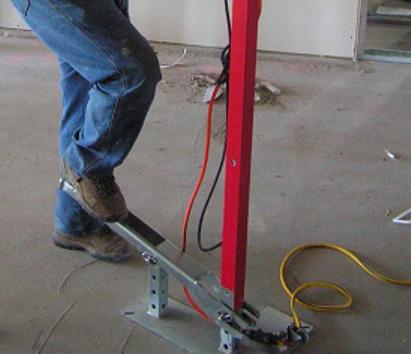
Figure 3.

Foot Lever Drill Press. [Robert Smithline with Interstate Mechanical, Inc at the PSU Oidine Hall Project in Portland, OR]
Figure 4.

Inverted Drill Press. [Kevin Day with Oregon Electric Group at the Swan Island Pump Station in Portland, Oregon]
Each intervention device consisted of a drill saddle, a telescoping column, a trigger switch and outlet, a method for raising the column, and base. The drill saddle was custom made to hold one of three of the most commonly used drills in the field. These drills were provided by the research team. A universal drill saddle was also developed that was adjustable so that it could hold any drill or roto-hammer in case the provided drills did not meet specifications of the task (Figure 5). The telescoping columns came in two forms—one that can be raised by a gear and track system controlled by a crank handle (as with the Inverted Drill Press) or one whose height could be adjusted by hand and locked with a pin (as with the Foot Lever Drill Press) (Figure 6). The base was a flat metal plate welded to the bottom of the column with two wheels that engaged when the device was tilted for transportation at the construction site (Figure 7). Each column had an outlet whose power could be controlled by a switch that was attached to the column near the column handle. The drill trigger was depressed continuously with a Velcro strap. When the drill was plugged into the outlet on the column, the operator could activate the drill by engaging the momentary on/off switch on the column.
Figure 5.

Three drills and four drill saddles. The saddles attach to the top of the drilling columns.
Figure 6.

Gravity pin for telescoping column of Foot Lever Drill Press is visible at the top of the lower red column.
Figure 7.
“T”-shaped Base of Foot Lever Drill Press.
Field Testing Generation 1 Devices
The two Generation 1 prototypes were tested by 14 construction workers on various commercial construction projects in Portland, Oregon. Two of the participants were women, 3 apprentices, 2 pre-apprentices and 9 journeymen. Seven of the 14 participants were sheet metal workers, 3 were from the piping trades, 3 were carpenters and 1 was an electrician. Each test included both the workers' usual method of drilling and drilling with the two intervention devices – the order of testing was randomized. An equivalent number of holes were drilled for each method. The tests were integrated into the usual activities involving drilling into concrete or metal ceilings. After each method was tested, the participant completed a questionnaire that scored the ease of use, fatigue levels, and functionality (accuracy, stability etc). Open ended questions also asked for suggestions for improving the device/method. After all three methods were tested, a final questionnaire was completed that asked participants to rank order each of the methods for various characteristics such as set-up time, moving to next hole, productivity, or overall rank. The tests were videotaped, photographed and observed by the team's field technician; this feedback helped the team to determine how the devices should be modified.
Based on the comparison ranking for ease of set-up and moving, 53% of the subjects preferred their usual method, 27% preferring the Inverted drill Press, and 18% preferred the Foot Lever Drill Press. The subjects found the intervention devices top heavy, awkward and cumbersome to move. The bases of the Generation 1 devices were flat metal plates that required the device to be rocked or kicked into position (See Figure 7).
Analysis of the video tapes revealed that, although the intervention devices took longer to move into position and to align the drill bit with the hole-mark, the actual drilling time was shorter with the devices than with the usual method. The devices allowed the operator to apply more force to the drill without fatigue. The comparison survey results were mixed. The usual method ranked first for set-up time, but the inverted drill press ranked first for work speed (drilling). The participants found the intervention devices easier on the body. However, due to the problem with slow set-up time and difficulty moving from hole to hole, the overall number one rating went to the usual method. A number of suggestions were made to speed up the set-up time and the time to move between holes.
Generation 2 Design
The device design was modified based on suggestions from the participants and the review of the videotapes. First, the inverted drill press design was selected over the foot lever design. Second, the design was modified by adding wheels to the base to make it easier to move around the construction site and easier to move between holes. Third, an adjustable positive stop was added to the drill saddle because it was difficult to see the depth of the drill bit during drilling (Figure 9). Fourth, a method was added for leveling the column so that the device could be lined up on a mark on the floor rather than on the ceiling. Finally, the device was made modular, with removable components (e.g., drill saddle, telescoping column, base), so that it was easier to transport and assemble on site.
Figure 9.

A make-shift positive stop was added next to the drill to prevent the drill bit from going too deep. The newer saddles have a build in adjustable stop. Inverted Drill Press. [Jennifer Robinson with Temp Control Mechanical at the Elliot Building, Portland, OR]
The inverted drill press design was selected over the foot lever design because the foot lever drill press design had features that were cumbersome. For example, the height of the column on the foot lever drill press had to be set manually which required the device to be tipped to the ground for adjustment; an awkward and strenuous movement, which often resulting in the drill hitting overhead obstacles when it was righted. Another problem had to do with the force required to depress the foot lever and the resting height of the foot lever; two subjects reported pain in their low backs upon depressing the foot lever. Finally, some operators found it awkward and unstable having to depress the foot lever in a controlled fashion for a prolonged period of time.
The column leveling innovation can eliminate the need to climb a ladder to mark the drill hole on the ceiling thereby improving productivity and decreasing fall risk. Two subjects demonstrated this improved efficiency during the Generation 1 field tests by aligning the center point of the device base with their marks on the floor, leveling the column using a torpedo level and drilling holes in the ceiling without having to climb a ladder to mark the ceiling holes. This field innovation was incorporated into the design of Generation 2; a plumb chain was added to the center of the base for aligning the device to a floor mark and small bubble levels were attached to the column.
A major design innovation involved developing three different interchangeable bases for supporting the column. Each base had 4 double-locking castors, so that the devices could be easily transported from one hole to the next (Figure 8). Enabling the devices to roll also eliminates the awkwardness of moving the device and made the top-heaviness less of an issue since the Generation 2 devices were not being tipped as much as the Generation 1 devices.
Figure 8.

Generation 2 device with four adjustable height and locking castors. The base is leveled by adjusting the height of each castor. Note levels on the base.
But each of the three interchangeable bases used a different method for leveling the column. The Spring Base was brought into plumb by pressing down on the base; each of the wheels was secured to the based with a spring. The Adjustable Castor Base was leveled by adjusting the height of each of the four castors with a knob and bolt. For the Collar Base the column could be tilted and locked into place with a collar about 2 feet above the ground (Figure 10).
Figure 10.

The Collar Base version of the Generation 2 inverted drill press.
Field Testing of Generation 2
The testing of the Generation 2 devices involved field testing with 16 subjects using the same methods as described above. The feedback on the Generation 2 devices was much better. All subjects rated the intervention devices as more comfortable. For overall rating, almost all (93%) of the subjects preferred one of the intervention devices over their usual method. Set-up time was still longer with the intervention device as compared to the usual method, but drilling time was much shorter with the device. In several tests with the Generation 2 devices, productivity was increased four-fold with the intervention devices as compared to the usual method.
The type of work and setting of the work affected the ease of use and the set-up time for the intervention devices. For example, drilling that occurred in “tenant improvement” projects (that is, remodel projects with construction occurring in existing buildings where overhead obstacles such as conduit, plumbing and duct work were pervasive) had mixed results. In some cases, the operators were able to direct the drill with the intervention device between narrow openings in the overhead obstacles to access the ceiling that they would not have been able to access when drilling by hand because they could not squeeze their bodies through and around the overhead utilities (Figure 13). However, in those cases, maneuvering the scissor lift with the device in the basket often was difficult and time-consuming because the operator had to maneuver the lift around obstacles on the ground while being limited by the clearance of the device among the overhead obstacles. Unlike the human body, the devices could not be leaned beyond the rails of the lift; therefore, an operator using a lift had to position the lift directly below the area where the hole needed to be drilled.
In another example that occurred on a hospital project, using the device in a scissor lift was impractical because the locations where the drilling occurred required access to small hospital rooms with low clearances through doors; the operators had to dismantle and reassemble the device in the lift after every two to four holes (Figure 14). The devices could reach the ceiling height of 15.5 ft from the ground only with the use of a fixed 4 ft extension for the column (normal working height of the devices without the extension was 12 ft), however since the overhead obstacles ranged in height from 8 ft to 10 ft above the ground, lateral movement of the devices was blocked or hindered by the fixed column extension's inference with the lower hanging obstacles.
The variation in field setting application yielded surprising results in others ways. The more difficult (strenuous, prolonged and awkward) the drilling was by hand, the better the devices were received. Sometimes the factors that made drilling difficult were counter-intuitive; one might think that drilling a larger diameter hole would be harder than drilling a small diameter one. However, the field testing showed that ceiling material and access to the ceiling were more critical factors than the diameter of the hole. In one such case, drilling a small diameter hole (11/64“) into a specialized aluminum ceiling with restricted access required several minutes (between 2 to 5 minutes) of awkward drilling by hand whereas drilling time with the devices ranged from 40 seconds to 90 seconds with very little perceived levels of fatigue.
Generation 3 Design
Based on feedback from field testing of Generation 2 devices, a final, Generation 3 device is being designed. The Generation 3 device will incorporate a version of the collar base because this base required the least amount of bending over to adjust the plumb of the column. The column of this device is leveled by tilting and locking the column within the collar of the base at chest level.
Having fours wheels on a base caused it to rock when the floor surface was uneven. Generation 3 will have only three wheels, but with a larger overall stance than Generation 2, so that the tipping risk is not increased.
Because of the challenges with clearing piping and ducts overhead, the participants recommended modifications be made to increase the working height of the device while decreasing the resting height. A low resting height would give the operator more opportunity to get the devices below overhead obstacles from both the ground and a lift, while a higher working height would allow the operators to use the device from the ground (which is often faster than using the device in a lift). The Generation 3 design may include a triple nested column rather than the double nested version of Generation 2. Triple nesting the columns should give the device a resting height at or near 6 ft and a working height up to 15.5 ft. Another modification was to add a hinge to the saddle so that the drill could be tilted down, thereby lowering the resting height of the column and making it easier to change bits.
Not all of the challenges identified by the subjects will be addressed by the Generation 3 design. It was observed in the field that more neck extension occurs with use of the device. Another feature that was not addressed was the difficulty with spotting the prospective hole when the device is used from the ground. Dust and debris falling from the ceiling onto the operator was another limitation identified by the subjects that was somewhat alleviated through the addition of a dust control system on one of the drills. The dust control system worked well, however it filled quickly and required frequent emptying and is only available on one model of drill from only one manufacturer.
The Next Step
Currently the Generation 3 device is being designed and fabricated and will be tested over the next year in field studies. The testing methods will be similar to those presented above but will also include measurement of shoulder and head postures using inclinometers.
Lessons Learned
The feedback, design suggestions and field testing by experienced construction workers was vital to the successful development of these devices. It is difficult to anticipate how intervention devices will perform and be received without testing in varied field settings. Experienced workers play a key role in the process because they are the most impacted by the intervention, they are experts in the work and they can identify both the nuanced and the obvious advantages and disadvantages of its application (Schneider, 2006).
In spite of the identified limitations of the Generation 1 devices, incorporating suggested modifications led to Generation 2 devices which received overall ratings that were better than the usual method. Based on these preliminary results, the development of an intervention device for overhead drilling has potential, but it must first undergo several rounds of field testing and modifications before it can be successfully implemented in the construction community. Field testing should be done with real tasks, in diverse field settings, with subjects familiar with the task. It is important that designers include an adequate number of rounds of testing and modification before settling on a final design.
Figure 11.

The image on the left shows the inverted drill press column with a 4 foot extension threaded between conduits in order to access an area for drilling. The device is being operated from the ground. The image on the right shows a participant unable to maneuver the lift any higher because of interference with overhead obstacles so he reaches beyond the rails of the lift in an awkward posture in order to drill by hand.
Figure 12.

The inverted drill press operated from a scissors lift Notice that the clearance of the lift below the door header would require that the device be dismantled and removed in order to move the lift between rooms. Since the subjects had only 2 to 4 holes to drill per room, using the device for this application was inefficient and time-consuming. [Andy Lawyer and Gary Wilson with Temp Control Mechanical]
Acknowledgments
This research is made possible by the Center to Protect Workers' Rights (CPWR) as part of a cooperative agreement with the National Institute of Occupational Safety and Health (NIOSH).
We are grateful for the voluntary participation of the participating construction workers and the following companies: Advanced Technology Group, Apollo Sheetmetal, ASD, Fortis Construction, J.H. Kelly, Interstate Mechanical Contractors, Oregon Electric Group, Rosendin Electric, Skanska USA, and Temp Control Mechanical.
Supplementary Material
References
- Hagberg M. Electromyographic signs of shoulder muscle fatigue in two elevated arm positions. American Journal of Physical Medicine. 1981;60(3):111–21. [PubMed] [Google Scholar]
- Holmstrom EB, Lindell J, Moritz U. Low back and neck/shoulder pain in construction workers: occupational workload and psychosocial risk factors. Part 2: Relationship to neck and shoulder pain. Spine. 1992;17(6):672–7. doi: 10.1097/00007632-199206000-00006. [DOI] [PubMed] [Google Scholar]
- Hunting KL, Welch LS, Cuccherini BA, Seiger LA. Musculoskeletal symptoms among electricians. American Journal of Industrial Medicine. 1994;25(2):149–163. doi: 10.1002/ajim.4700250202. [DOI] [PubMed] [Google Scholar]
- Schneider SP. Measuring ergonomic risk in construction.. Proceedings of the 16th Congress of the International Ergonomics Association; The Netherlands. 2006. [Google Scholar]
- National Institute for Occupational Safety and Health (NIOSH) National Occupational Research Agenda (NORA) Update, 21 Priorities for the 21st Century. Department of Health and Human Services, Centers for Disease Control; Cincinnati, OH: 1999. [Google Scholar]
- National Institute for Occupational Safety and Health (NIOSH) Proceedings of a meeting to explore the use of ergonomics interventions for the mechanical and electrical trades, February 25−26; Cincinnati, OH. Department of Health and Human Services, Centers for Disease Control; 2002. 2002. NIOSH Publication Number 2006−119. [Google Scholar]
- Nussbaum MA, Clark L, Kirst M, Rice K. Fatigue and endurance limits during intermittent overhead work. American Industrial Hygiene Association Journal. 2001;62(4):446–456. doi: 10.1080/15298660108984646. [DOI] [PubMed] [Google Scholar]
- Olson P. Musculoskeletal disorders of the neck-shoulder region related to working positions in the construction industry. Bygghalsan Bulletin: 1987−05−01. 1987 English Abstract. [Google Scholar]
- Welch L, Hunting K, Kellogg J. Work-related musculoskeletal symptoms among sheet metal workers. American Journal of Industrial Medicine. 1995;27(6):783–791. doi: 10.1002/ajim.4700270603. [DOI] [PubMed] [Google Scholar]
Associated Data
This section collects any data citations, data availability statements, or supplementary materials included in this article.