Abstract
Combined cup and stem anteversion in THA based on femoral anteversion has been suggested as a method to compensate for abnormal femoral anteversion. We investigated the combined anteversion technique using computer navigation. In 47 THAs, the surgeon first estimated the femoral broach anteversion and validated the position by computer navigation. The broach was then measured with navigation. The navigation screen was blocked while the surgeon estimated the anteversion of the broach. This provided two estimates of stem anteversion. The navigated stem anteversion was validated by postoperative CT scans. All cups were implanted using navigation alone. We determined precision (the reproducibility) and bias (how close the average test number is to the true value) of the stem position. Comparing the surgeon estimate to navigation anteversion, the precision of the surgeon was 16.8° and bias was 0.2°; comparing the navigation of the stem to postoperative CT anteversion, the precision was 4.8° and bias was 0.2°, meaning navigation is accurate. Combined anteversion by postoperative CT scan was 37.6° ± 7° (standard deviation) (range, 19°–50°). The combined anteversion with computer navigation was within the safe zone of 25° to 50° for 45 of 47 (96%) hips. Femoral stem anteversion had a wide variability.
Level of Evidence: Level II, therapeutic study. See the Guidelines for Authors for a complete description of levels of evidence.
Introduction
Impingement of the cup and stem or of bone-on-bone is the cause of dislocation, accelerated wear, and pain in patients with total hip arthroplasty [22]. Accuracy of femoral stem anteversion and acetabular cup anteversion would ensure mating of the femoral head in the cup without impingement of the two throughout all body positions. This requires a technique to repeatedly create this combined anteversion. Combined anteversion in the hip means the sum of the anteversion of the acetabulum and the femur. In total hip arthroplasty (THA) it means the sum of the cup and stem anteversion. McKibbin [24] first introduced the term in a study of infant cadavers and defined 30° to 40° combined anteversion as being normal, with 15° anteversion of the femur. Men had lower combined anteversion than women. In a study of 200 adult cadavers, the combined anteversion for men was a mean 29.6° and women 33.5°, with femoral anteversion a mean 11.6° (men were 11.1° and women 12.2°) [23]. A finite element study of THA investigated combined anteversion to find an optimal combination to avoid impingement and concluded it was 37.3° [31]. Mathematical models also confirmed combined anteversion to be the measurement that must be considered to avoid impingement [33]. Clinical use of combined anteversion has determined men to be between 25° and 35° and up to 45° in women [29].
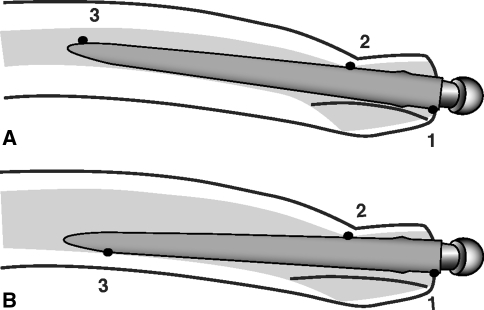
Combined anteversion has become more relevant with the use of noncemented implants. The noncemented femoral stem must have a stable press fit to obtain bone fixation. A stable press fit means the stem must adapt to the femoral bone geometry which is highly variable; accordingly, there is often less ability to adjust the stem anteversion in uncemented compared to cemented stems. One study has range of femoral anteversion from −15° (retroversion) to 30° (anteversion) in adult cadavers [23]. Our experience with computer navigation has a range of 17° retroversion to 28° anteversion of cementless femoral stems, and two other studies using postoperative CT scans found 30° retroversion to 45° anteversion of both cemented and cementless stems [28, 32]. Cemented stems can be rotated within the femoral bone to provide 10° to 20° anteversion. Cementless stems of any geometry are limited by the anteversion of the bone, the anteroposterior isthmus at the level of the lesser trochanter, and the posterior fin of bone in Dorr type A and B bone [8, 11, 22, 23] (Fig. 1A–B). Tapered stems have up to 5° of freedom of rotation whereas metaphyseal-filling stems are inflexible.
Fig. 1A–B.
(A) Diagram illustrates the anteversion of the femoral stem controlled by the anteversion of the neck, the anteroposterior isthmus (anterior cortex and true femoral calcar) at the level of the lesser trochanter, and the posterior fin of bone in types A and B. Femoral stem anteversion decreases as the bow of the femur increases or the posterior fin thickness increases. 1, 2, and 3 are three points of rotational stability. (B) Type C osteoporotic bone has a wide intramedullary canal so the isthmus and diaphysis have less influence on the stem anteversion. 1, 2, and 3 are three points of rotational stability.
The acetabular cup position has traditionally been anteverted with the assumption the femoral component would be a mean 15° anteverted. The arthritic acetabulum has a mean 12° anteversion [10] and nonarthritic acetabula have mean anteversion of 19.9° ± 6.6° with the mean in women being 21.3° and men 18.5° [23]. Therefore, the traditional safe zone for cup placement has been 15° ± 10° or 20° ± 10° [2, 22]. If the stem has only 5° of anteversion, especially in a woman, the acetabular safe zone of 15° to 20° does not give an acceptable combined anteversion [29, 31]. This risk is compounded in 10% of hips in which the pelvis is tilted 10° or more from neutral and the surgeon’s estimate of anteversion can be wrong by 10° [13]. In clinical studies, cup anteversion is not within the desired safe zone as often as 55% to 78% of the time [6, 16, 18, 19].
We therefore thought it important to ascertain how to obtain the best combined anteversion to prevent impingement of the stem on the cup (we were aware that avoidance of bone-on-bone impingement requires correct reconstruction of the hip length and offset) [22]. We had already established the advantage of imageless computer navigation, which measures pelvic tilt, in accurately positioning cup anteversion on the coronal plane of the body [13]. Our concern, therefore, was how to measure femoral anteversion so that a combined anteversion in a safe zone of 25° to 50° could be obtained every time. We raised the upper limit of the safe zone from 45° [29] to 50° because we had experienced anterior dislocations only if more than 50° combined anteversion were present.
We therefore raised three questions: (1) Can computer navigation measure femoral stem anteversion with a precision of 5° and can surgeons estimate the femoral anteversion as precisely as that measured by computer navigation? (2) Can computer navigation quantitatively keep the combined anteversion in the safe zone of 25° to 50° for each patient? (3) Can the surgeon accurately estimate correct combined anteversion with the Ranawat test? [29].
Materials and Methods
We compared the surgeon’s estimate of combined anteversion to that by navigation and postoperative CT scan in 46 patients (47 hips). Institutional Review Board approval for CT scans was obtained, as was informed consent for prospective review of data from each patient. Demographics included 41% female gender and a mean age of 62.1 ± 8.6 years (Table 1). The reason for surgery was osteoarthritis in 42 hips, dysplasia in three, avascular necrosis in one, and posttraumatic arthritis in one.
Table 1.
Patient demographics
| Demographic | Patients with navigated femur |
|---|---|
| Number of patients (hips) | 46 (47) |
| Gender (male/female ratio) | 19/28 |
| Age (years)* | 62.1 ± 8.6 |
| Height (cm)* | 175.9 ± 9.0 |
| Weight (kg)* | 85.6 ± 13.6 |
| Body mass index (kg/m2)* | 27.7 ± 4.0 |
* Values are expressed as mean ± standard deviation.
The concept of quantitative positioning of implants is applicable to all designs. We used implants we have long employed. The cementless stem was the anatomic porous replacement [15, 20] (APR®; Zimmer, Warsaw, IN) and the cup was the Converge (Zimmer), which is the successor to the anatomic porous replacement cup [14], with the singular change being a better locking mechanism.
The details of the operative technique, which prepares the femur first, have been published previously (Appendix 1) [10, 12, 17]. We had already shown this computer navigation system allows precise placement of the cup for both anteversion and inclination [13]. One experienced surgeon (LDD) performed all surgeries using the posterior mini-incision [17]. All patients had primary THA performed using the Navitrack® imageless computer navigation system (ORTHOsoft, Inc, Montreal, Canada), whose numeric cup values are reported using the radiographic measurement of Murray [25]. Navigation was used for cup positioning in all hips. Both instrumented navigation for measurement of femoral stem anteversion and the physician estimate of stem anteversion were performed in all 47 hips.
All 46 patients had a postoperative CT scan (Mx8000™; Phillips, Highland Heights, OH). Each scan was performed at 1.3-mm intervals and 1.3-mm thickness with a field of view of 400 and pitch of 1.250. We obtained 450 to 550 scans for each patient from the level of the fourth lumbar vertebra proximally to the entire distal femoral condyles. The information was stored and transferred in the standard Digital Imaging and Communications in Medicine (DICOM) format to the measurement systems [3, 4]. The CT scans were measured using two CT measurement systems to validate the CT measurements. The CT position of both the cup and the stem were measured without knowledge of computer navigation values; the measurements for the cup were performed by one observer (AM) and for the stem by a second (ZW). The measurements were made using the hip plan module of the Navitrack® system (Navitrack® computed tomography-based hip application; ORTHOsoft, Inc), which required 2 to 4 hours to load, manually segment, and reconstruct the 3-D model for determining implant position.
A virtual 3-D model of the patient’s pelvis, as well as the implanted cup and femur, were reconstructed using the DICOM files [3, 4]. The anterosuperior iliac spines and pubic tubercle midpoint were used to establish an anatomic coordinate reference system for the cup. A virtual cup from the database of the CT system was positioned over the reconstructed cup to match its position and orientation so that inclination and anteversion could then be measured. The Navitrack® system was programmed to report Murray’s radiographic definitions of cup anteversion and inclination [25].
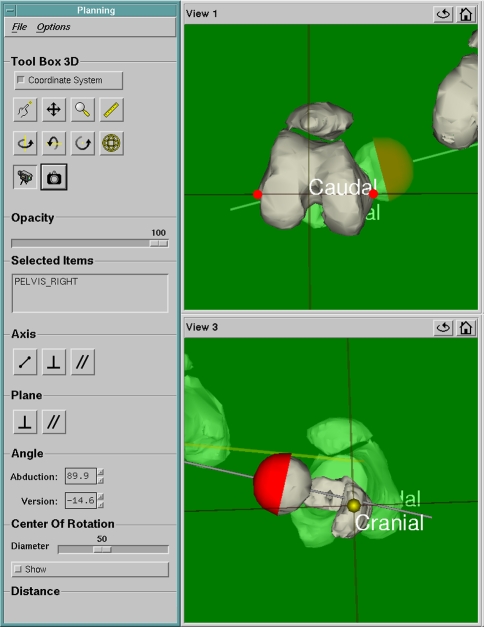
The postoperative CT femoral stem anteversion was measured using the Navitrack® 3-D reconstruction system on the plane of the greater trochanter proximally and femoral epicondyles distally (the same plane as the computer navigation software) (Fig. 2).
Fig. 2.
A screenshot image of the Navitrack® CT scan-based module shows how femoral anteversion is determined. The virtual model femoral head is positioned over the implant femoral head and aligned until the axis of the model coincides with the axis of the proximal head and neck. Anteversion is the angle between this axis and the femoral plane established as the plane passing through both medial and lateral epicondyles of the femur and the mid-high point of the greater trochanter.
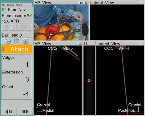
Femoral anteversion was measured by (1) surgeon estimate of broach anteversion validated by computer navigation, and (2) stem anteversion measured by intraoperative computer navigation validated by postoperative CT scans (Fig. 3). Combined anteversion was the sum of stem and cup anteversion and was measured both by the sum of stem and cup anteversion with intraoperative computer navigation and stem and cup anteversion on postoperative CT scan. Outliers of combined anteversion from the safe zone of 25° to 50° were identified, both by computer navigation and by CT scan.
Fig. 3.
A screenshot image of the Navitrack® navigation screen shows femoral anteversion when using a tracked femoral broach or stem inserter as shown in the inset in the upper left-hand corner. Anteversion is 3°, stem is in 1° valgus, and with a neutral head the offset of the femoral head is decreased 4 mm. CC is craniocaudal height of the femoral head center which in increased 5 mm; mL is the mediolateral displacement of the head center which is 5 mm medial; AP is anteroposterior displacement of head center which is 4 mm posterior which contributes to retroversion of the stem (see Fig. 1).
The broach anteversion was judged by the experienced surgeon and the fellows (AM, MD). These estimates were similar (0.77, p = 0.591) so for data analysis only the experienced surgeon estimates were used. The surgeon estimate was compared to the computer navigation value. The computer screen was hidden from the view of the surgeon while the broach anteversion estimate of the surgeon was recorded. The broach was used instead of the stem because if the stem was inserted at this time it would interfere with the preparation of the acetabulum.
The Ranawat test [29] for combined anteversion between the cup and stem was performed in 33 hips and compared to the reference value of the postoperative CT scan combined anteversion for that hip. This test is a visual judgment of the combined anteversion when the femoral neck and head are aligned coplanar to the acetabular mouth. The degree of internal rotation to produce a coplanar head and cup is the combined anteversion.
We used the Kolmogorov-Smirnov test to ascertain normal distribution before further statistical analysis was conducted. We computed the means and standard deviations. Student’s t test was used to compare femoral anteversion and combined anteversion between men and women. The repeatability between femoral anteversion of computer navigation and CT scans was calculated using intraclass correlation coefficient by reliability analysis. A p value less than or equal to 0.05 was considered statistically different. To compare accuracy of femoral and combined anteversion, the bias and precision were calculated according to the American Society for Testing and Materials definitions [1]. Bias is defined as the numerical value difference between the average value of all the measurements (ie, surgeon estimate, navigation value, CT value) and the reference value. For example, a low bias number means that the average of the test number and true value are very close. Precision is defined as the closeness of agreement between independent measurements (in degrees in this study) of the same condition. For example, a low precision number means that the test is very reproducible. For measurement of methods, the means with standard deviations are not as important as the precision, bias, and number of outliers because that data reveals how often the measurement method is accurate. Statistical analysis was performed with SPSS software (SPSS Inc, Chicago, IL).
Results
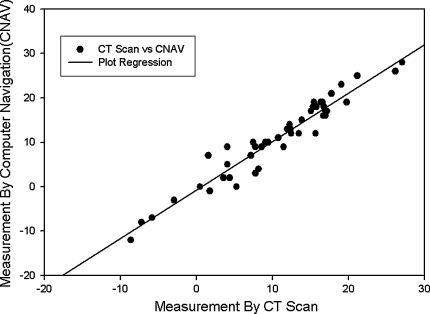
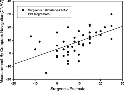
The first question we asked was whether computer navigation can measure stem anteversion with a precision of 5° and whether surgeons can estimate femoral broach anteversion as precisely as that measured by computer navigation. Computer navigation was more precise than the surgeon and was able to measure with a precision of 5° as validated by the postoperative CT scans (Table 2). There were no outliers of 6° or more of stem anteversion by computer navigation. The mean stem anteversion on postoperative CT scan and computer navigation was essentially the same (Table 3). Between intraoperative computer navigation and postoperative CT scan the precision was 4.8° and the bias 0.2°. We observed a close relationship between computer navigation and CT scan femoral anteversion (Fig. 4). Surgeons could not measure femoral anteversion as precisely as computer navigation with surgeon estimates having a precision of 16.8° and a bias of 0.3° (Table 2). The surgeon’s estimates had outliers of 6° to 10° in 11 of 47 (23.4%) hips and more than 10° in 11 of 47 (23.4%), which gives wide scatter on linear regression (Fig. 5).
Table 2.
Precision and bias in femoral anteversion determination (n = 47 hips)
| Determination method | Femoral anteversion* | Precision (°) | Bias (°) | Intraclass coefficient | Correlation coefficient (p value) |
|---|---|---|---|---|---|
| Surgeon estimate broach | 8.6 ± 8.9 | 16.8† | 0.3† | 0.73† | 0.57 (p = 0.000) |
| Computer navigation broach | 8.4 ± 9.1 | ||||
| Computer navigation stem | 10.9 ± 9.0 | 4.8‡ | 0.2‡ | 0.96‡ | 0.97 (p = 0.000) |
| CT scan stem | 10.6 ± 8.0 |
* Values are expressed as mean ± standard deviation; †experienced surgeon’s estimate versus the computer navigation broach femoral anteversion; ‡computer navigation final femoral stem anteversion versus the postoperative computed tomography scan anteversion.
Table 3.
Anteversion measurements (n = 47)
| Type of anteversion | Anteversion (°) | |
|---|---|---|
| Computer navigation | CT scan | |
| Femoral | 10. 9 ± 9.0 (−12–28) | 10.6 ± 8 (−8.6–27.1) |
| Cup | 25.1 ± 4.6 (14–36) | 27 ± 4.6 (8.8–38.7) |
| Combined | 35.9 ± 6.7 (16–47) | 37.6 ± 7 (19–50) |
Values are expressed as mean ± standard deviation, with range in parentheses.
Fig. 4.
Femoral stem anteversion of 47 APR® stems measured by computer navigation compared to CT scan shows excellent regression. The solid line represents a simple linear regression fit (r = 0.97, p = 0.000).
Fig. 5.
Femoral stem anteversion of 47 APR® broaches measured by computer navigation compared to surgeon’s estimation shows wide scatter. The solid line represents a simple linear regression fit (r = 0.57, p = 0.000).
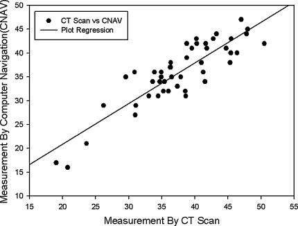
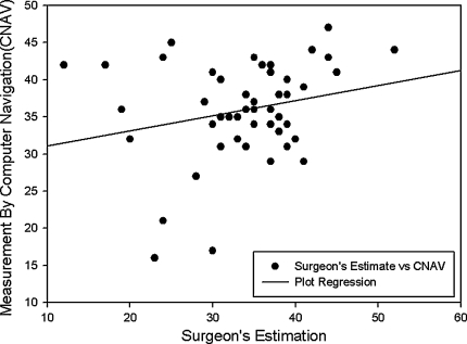
The second question we asked was whether computer navigation can quantitatively keep the combined anteversion within the safe zone (25°–50°) for each patient. The combined anteversion with computer navigation was within the safe zone for 45 of 47 (96%) hips. Postoperative CT scans had the same values for the same hips (96% in safe zone). The mean combined anteversion was 35.9° ± 6.7° (range, 16°–47°) by computer navigation and 37.6° ± 7.0° (range, 19°–50°) by postoperative CT scan (Table 3). There were two hips known intraoperatively to have a combined anteversion less than 25° (19° and 21°) and were accepted because the stem was retroverted (−5.7° and −7.4°) and the cup was anteverted as much as anatomically possible. It is difficult to antevert a cup more than 30° without uncovering the cup posteriorly, or reaming excessively medially or superiorly. In these two hips, stability without manually palpated impingement was present throughout the range of motion. Intraoperative computer navigation combined anteversion was superior to the surgeon’s estimate of femoral anteversion plus the navigated cup anteversion which had eight outliers from the safe zone. For combined anteversion determined by computer navigation, the precision was 4.8° and bias was 0.2° (ICC = 0.96) with good linear regression (Fig. 6); for the surgeon’s estimates the precision was 18° and bias was 3.7° (ICC = 0.5) with wide scatter on linear regression (Fig. 7).
Fig. 6.
Combined cup and stem anteversion of 47 hips measured by computer navigation compared to CT scan shows good regression. The solid line represents a simple linear regression fit (r = 0.88, p = 0.000).
Fig. 7.
Combined cup and stem anteversion of 47 hips measured by computer navigation compared to surgeon’s estimation shows poor regression with wide scatter. The solid line represents a simple linear regression fit (r = 0.24, p = 0.11).
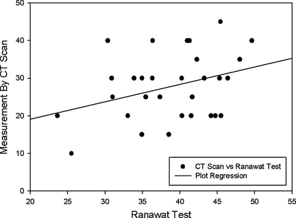
The third question we asked was whether the visual Ranawat test accurately measured combined anteversion after THA. This test had a mean combined anteversion of 27.8° ± 8.8° (range, 15°–45°) and the postoperative CT combined anteversion of the same hips was 38.8° ± 7.8° (range, 13.6°–49.6°). The precision was 19° and the bias was 11° with the same scatter (Fig. 8) as the surgeon’s estimates of combined anteversion (Fig. 7).
Fig. 8.
A plot of combined cup and stem anteversion of 33 hips measured by computer navigation compared to Ranawat test shows wide scatter. The solid line represents a simple linear regression fit (r = 0.33, p = 0.11).
Discussion
We investigated whether computer navigation provided improved technical ability for the surgeon to achieve correct combined anteversion of the stem and cup for THA as compared to the surgeons’ experience and judgment. We asked the questions: (1) Can computer navigation measure femoral stem anteversion with a precision of 5° and can surgeons estimate the femoral anteversion as precisely as that measured by computer navigation? (2) Can computer navigation quantitatively keep the combined anteversion in the safe zone of 25° to 50° for each patient? (3) Can the surgeon accurately estimate correct combined anteversion with the Ranawat test? In this study, we focused on cementless femoral stem anteversion and the technique of positioning the stem and cup by the concept of combined anteversion because we had previously published the accuracy of computer navigation for cup anteversion [13].
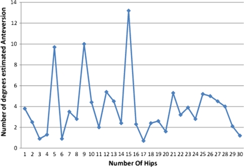
There were several limitations to our study. The precision of surgeon estimates can vary from surgeon to surgeon and might differ from those of the surgeon in this study. There is also a learning curve, and for the surgeon in this study, the precision of the estimate improved after 15 hips (Fig. 9). The more the surgeon concentrates on judging the femoral anteversion, the better the estimate. The estimate by broach may have been improved if a trial neck and head were placed on the broach because this improves the 3-D visualization of the implant anteversion to the leg axis. In 30 Zweymüller stems (Zimmer, Inc.) subsequently studied with surgeon estimates and postoperative CT scans, there were only two of 30 (6.7%) with a surgeon estimate outlier of more than 10° and four of 30 (13.4%) with 6° to 10° outliers. This reflects the surgeon’s experience and the use of a trial stem for estimate. The second limitation is that these results for precision and bias are specific to the Navitrack® navigation system and cannot be transposed to other navigation systems. Differences between systems include the algorithms and mathematical models used in the software for measurement of implant position. The third limitation is that our results are from the posterior approach. Surgeons who operate with the patient in the supine position may visualize the femur and cup in a different plane.
Fig. 9.
The estimated anteversion (degrees) could be determined within 5° of the reference value by surgeon estimate alone after a learning curve of 15 hips.
The first question was whether the femoral stem anteversion by computer navigation would have a precision of 5° and be better than a surgeon’s estimate. The answer was affirmative because precision of the navigation system for femoral anteversion was 4.8° with no outliers beyond 6°. Using the surgeon’s estimate of femoral anteversion in the same hips, the precision was 16.8° and there were 11 of 47 (23.4%) outliers between 6° and 9° and 11 of 47 (23.4%) more than 10°. Our data confirmed a wide variability of femoral anteversion with cementless stems of both the so-called anatomic designs used in this study and our experience with the tapered Zweymüller. In 82 hips, in which both stems were used, 35 stems (43%) had 10° to 20° of anteversion; eight (10%) were in absolute retroversion (−2.9° to −8.6°); 34 (41.5%) had anteversion of 0° to 9°; and five of 82 (5.5%) had more than 20° of femoral anteversion (21°–27.1°). Two other studies confirm this wide variability of stem position in THA [28, 32]. It is probable that the increased prevalence of dislocations, as a cause of revision, with cementless THA is because of this variability of cementless stem position [9].
Our second question was whether combined anteversion of the femoral stem and cup would be within the safe zone of 25° to 50° in each patient. There is a wide safe zone of 25° to 50° for combined anteversion for THA, which explains why most THAs are successful when performed using the surgeons’ experience and judgment alone. Combined anteversion is nature’s method of stability and it is the most important measure for stability of a THA [21, 23, 24]. Measurement of the acetabular position alone is not diagnostic of the cause of dislocation [28]. Combined anteversion explains why the hip remains stable throughout the wide flexion arc (35°) of the acetabulum in the change of body position from supine to sitting [5, 26]. Reference to a safe zone for THA in the future should be to combined anteversion, rather than isolating a safe zone for the acetabulum. The safe zone for combined anteversion is 37° ± 12° in our studies, and the mean of 37° agrees with finite element data [31]. Combined anteversion is lower in men mostly because femoral anteversion is lower (mean 8.7° in men versus 10.7° in women in our study). To reproducibly accomplish the combined anteversion requires femoral preparation first so the cup can be adjusted to the stem. This requires change by the surgeon in the order of the operation, which is initially disruptive, but knowledge of femoral stem anteversion prior to acetabular position has been preferable in laboratory studies as well as by this clinical study [31, 33].
The third question of our study was whether the visual method of estimating combined anteversion by the Ranawat test was accurate, and it was not (Fig. 8). The precision of surgeons with visual estimates seems to have a similar pattern no matter the test (Figs. 5, 7, 8). Achieving accuracy with combined anteversion by computer navigation does give precision of both acetabular and femoral component positions. The cup can be accurately placed within 5° on the coronal plane when pelvic tilt is measured as shown in our prior study where computer navigation cup anteversion had a precision of 4.1° and a bias of 0.73° [13]. Cup anteversion will always be best determined by computer navigation because the surgeon cannot know the tilt of the pelvis. In our experience, the tilt changes cup anteversion by 10° or more from that visualized in 7.5% of hips and 6° to 9° in 21% of hips. In this study, we validated femoral stem anteversion by computer navigation to also be within 5° (precision, 4.8°; bias, 0.3°), but with experience the surgeon’s judgment can be within 5° 85% to 90% of the time (Fig. 9).
The combined anteversion technique for cementless stems can assure elimination of stem-on-cup impingement if it is combined with correct coverage of the cementless cup and correct hip length and offset. Correct coverage of the cup may require medializing the center of rotation so the inclination can be kept below 45° and the metal edges are flush with the bone (except posterior-superior) [30]. Elimination of impingement provides the best condition for minimizing wear and optimizing stability [7, 12, 27].
Intraoperative quantitative knowledge improves the technical performance of the surgeon. Preoperative templating does not substitute for intraoperative knowledge because plain radiographic techniques do not allow the surgeon to reliably predict femoral anteversion. Independent of this study and using 57 hips with preoperative crosstable lateral radiographs templated with both the anatomic and tapered stems we compared the preoperative templated femoral anteversion to postoperative CT scan anteversion and found a precision of 21.4° (unpublished data).
Our method of performing cementless THA at this time is to prepare the femur first, estimate the femoral stem anteversion, and then implant the cup with computer navigation. Our goal is a combined anteversion of 25° to 45° with a mean of 35°. Lower combined anteversion occurs when the femoral stem anteversion is low (more common in men). If anatomic stem anteversion is low it is better to compensate with more cup anteversion than increasing stem anteversion to 15° to 20° to avoid intoeing of the leg and foot by creating a new anteverted position of the leg. If the stem is to be cemented, we implant the cup at 20° to 25° anteversion and cement the stem at 10° to 15° anteversion, lower for low anatomic anteversion. We obtain 40° inclination with computer navigation. We always use the largest femoral head that can be implanted with highly crosslinked polyethylene according to the acetabular size.
Acknowledgments
We thank Patricia Paul for her help in preparing this manuscript.
Appendix 1. Operative Technique
Computer Registration for Navigation
The instrumentation for computer navigation was calibrated while the patient was prepared for anesthesia. After the patient was anesthetized, a metal base plate for the pelvic tracker was secured with three 1/8-inch threaded pins to the thickest portion of the pelvic brim. With the patient supine, the anterior pelvic plane registration was performed by bony contact to both anterosuperior iliac spines and the pubic bone near the pubic tubercles. The skin and fat over the pubis (mons pubis) was always punctured to contact the pubic bone. In obese patients with approximately 5 mm of skin and fat over the anterosuperior iliac spines, a stab wound to the bone was made to insure bone contact. The patient was then “flipped” to the lateral position and secured with two pelvic supports and two chest supports (Sunmed, Redding, CA). The registration pointer was used to contact the two posterior supports with three points in triangular geometry to register the longitudinal axis of the body. The software can then compute the tilt of the pelvis relative to this longitudinal reference plane. The pelvic tilt permits adjustment of inclination and anteversion into the radiographic coronal plane.
The femoral pins and tracker were placed with the patient in the lateral position. The femoral baseplate was attached to the anterior lateral femur 8 cm cephalad from the superior pole of the patella and anterior to the palpable anterior edge of the iliotibial band. The pins were drilled through the anterior lateral cortex into, but not through, the medial cortex. For determination of femoral anteversion the longitudinal plane of the leg is registered. This is done after the incision and posterior approach have been undertaken with exposure of the greater trochanter but before femur dislocation. Five points are registered: the greater trochanter, the two femoral epicondyles, and two ankle malleoli. The knee must be at 90° of flexion. These points are used to determine the plane of the leg from which the software defines the femoral plane to determine femoral anteversion. In obese patients the epicondyles are difficult to identify percutaneously and this may contribute to inaccurate values of the plane of the leg and consequently femoral anteversion. The navigation system software was programmed only for the APR anatomic stem (Zimmer, Warsaw, IN) during the time of this study.
Posterior Approach
The incision is made over the posterior border of the greater trochanter, and extends proximally from the level of the vastus tubercle for 10 cm cephalad. The first incision into hip tissue is done in the gluteus maximus muscle, which is incised for 6 to 8 cm along the posterior border of the greater trochanter. The second is through the small external rotators and the posterior capsule with the leg in internal rotation. It is made as a single flap from just proximal to the quadratus femoris muscle either to or through the piriformis tendon. If the piriformis tendon is transected, the incision extends through 1 to 2 cm of the gluteus minimus muscle. In flexible hips, the piriformis tendon is preserved and an L-shaped incision is made with one arm parallel to the piriformis tendon. The hip is dislocated and the corresponding templated neck cut for restoration of leg length made. The third incision is of the inferior medial capsule, which is incised from the anterior femur to the acetabulum through the transverse acetabular ligament.
Femoral Preparation
The preparation of the femur was performed first so that the anteversion of the femur was known prior to the preparation and implantation of the acetabulum. The femur is presented into the wound by positioning of long-handled retractors (Zimmer, Warsaw, IN). Femoral preparation was done by reaming and broaching. Five points of the intramedullary canal of the femur were registered with a metal registration tool. The software could then determine the position of the implants in the femoral bone by calculating the intramedullary canal relative to the plane of the leg. The anteversion of the broach (and subsequently the stem) was computed as it was implanted into the bone and displayed on the computer screen.
Acetabular Preparation
Three long-handled retractors are placed to obtain correct exposure of the acetabulum.The labrum is removed as is any floor osteophyte overlying the cotyloid fossa. The cortical bone of the cotyloid notch is registered as the medial wall. Two registrations of the native acetabulum are done prior to acetabular preparation. (1) The acetabulum is digitized 16 times to obtain the center of rotation and diameter of the bony acetabulum. (2) Four points on the cortical bone of the cotyloid notch digitized the medial wall. The change in center of rotation by depth of reaming in both the medial and superior directions can be visualized on the computer screen. Reaming medially is done to the cotyloid notch which medializes the center of rotation 3 to 6 mm; removal of the lunate bone and formation of a hemisphere moves the center of rotation cephalad to 5 mm. The cup is targeted to 40° ± 5° inclination and the anteversion is customized according to the femoral anteversion to provide a combined anteversion of 30° to 45° (with 5° margin of error for safe zone of 25° to 50°), lower for men and hips with low femoral anteversion, and higher for women and hips with high femoral anteversion. The coverage of the cup is to have the inferior-medial edge flush with the cortical bone of the cotyloid notch (just inside the transverse acetabular ligament) and 3 mm below the pubis cortex; the anterior-superior edge is level with the anterior iliac bone; posteriorly, it is below the ischial cortex and may be prominent by up to 3 mm posterior-superiorly.
Footnotes
One or more authors (LDD) have received funding from Good Samaritan Hospital (Los Angeles, CA) for conducting this study.
Each author certifies that his or her institution has approved the human protocol for this investigation, that all investigations were conducted in conformity with ethical principles of research, and that informed consent for participation in the study was obtained.
References
- 1.ASTM. Standard Practice for Use of the Terms Precision and Bias in ASTM Test Methods. In: Annual Book of ASTM Standards ed. Philadelphia, PA: American Society for Testing and Materials; 2002:E177–E190a.
- 2.Barrack RL, Lavernia C, Ries M, Thornberry R, Tozakoglou E. Virtual reality computer animation of the effect of component position and design on stability after total hip arthroplasty. Orthop Clin North Am. 2001;32:569–577. [DOI] [PubMed]
- 3.Best DE, Horii SC, Bennett W, Thomson B, Snavely D. Review of the American College of Radiology–National Electrical Manufacturers’ Association standards activity. Comput Methods Programs Biomed. 1992;37:305–309. [DOI] [PubMed]
- 4.Bidgood WD Jr, Horii SC. Introduction to the ACR-NEMA DICOM standard. Radiographics. 1992;12:345–355. [DOI] [PubMed]
- 5.DiGioia AM, Jaramaz B, Blackwell M, Simon DA, Morgan F, Moody JE, Nikou C, Colgan BD, Aston CA, Labarca RS, Kischell E, Kanade T. The Otto Aufranc Award. Image guided navigation system to measure intraoperatively acetabular implant alignment. Clin Orthop Relat Res. 1998;355:8–22. [DOI] [PubMed]
- 6.DiGioia AM 3rd, Jaramaz B, Plakseychuk AY, Moody JE Jr, Nikou C, Labarca RS, Levison TJ, Picard F. Comparison of a mechanical acetabular alignment guide with computer placement of the socket. J Arthroplasty. 2002;17:359–364. [DOI] [PubMed]
- 7.D’Lima DD, Chen PC, Colwell CW Jr. Optimizing acetabular component position to minimize impingement and reduce contact stress. J Bone Joint Surg Am. 2001;83(Suppl 2 Pt 2):87–91. [DOI] [PubMed]
- 8.D’Lima DD, Urquhart AG, Buehler KO, Walker RH, Colwell CW Jr. The effect of the orientation of the acetabular and femoral components on the range of motion of the hip at different head-neck ratios. J Bone Joint Surg Am. 2000;82:315–321. [DOI] [PubMed]
- 9.Dobzyniak M, Fehring TK, Odum S. Early failure in total hip arthroplasty. Clin Orthop Relat Res. 2006;447:76–78. [DOI] [PubMed]
- 10.Dorr LD. Hip Arthroplasty, Minimally Invasive Techniques and Computer Navigation. Philadelphia, PA: Saunders, Elsevier; 2006.
- 11.Dorr LD, Faugere MC, Mackel AM, Gruen TA, Bognar B, Malluche HH. Structural and cellular assessment of bone quality of proximal femur. Bone. 1993;14:231–242. [DOI] [PubMed]
- 12.Dorr LD, Hishiki Y, Wan Z, Newton D, Yun A. Development of imageless computer navigation for acetabular component position in total hip replacement. Iowa Orthop J. 2005;25:1–9. [PMC free article] [PubMed]
- 13.Dorr LD, Malik A, Wan Z, Long WT, Harris M. Precision and bias of imageless computer navigation and surgeon estimates for acetabular component position. Clin Orthop Relat Res. 2007;465:92–99. [DOI] [PubMed]
- 14.Dorr LD, Wan Z. Ten years of experience with porous acetabular components for revision surgery. Clin Orthop Relat Res. 1995;319:191–200. [PubMed]
- 15.Harris M, Dorr LD, Wan Z, Sirianni L, Boutary M. Total hip arthroplasty with the APR stem and cup follow-up of a previous report. J Arthroplasty. 2005;20:828–831. [DOI] [PubMed]
- 16.Hassan DM, Johnston GH, Dust WN, Watson G, Dolovich AT. Accuracy of intraoperative assessment of acetabular prosthesis placement. J Arthroplasty. 1998;13:80–84. [DOI] [PubMed]
- 17.Inaba Y, Dorr LD, Wan Z, Sirianni L, Boutary M. Operative and patient care techniques for posterior mini-incision total hip arthroplasty. Clin Orthop Relat Res. 2005;441:104–114. [DOI] [PubMed]
- 18.Jolles BM, Genoud P, Hoffmeyer P. Computer-assisted cup placement techniques in total hip arthroplasty improve accuracy of placement. Clin Orthop Relat Res. 2004;426:174–179. [DOI] [PubMed]
- 19.Kalteis T, Handel M, Bathis H, Perlick L, Tingart M, Grifka J. Imageless navigation for insertion of the acetabular component in total hip arthroplasty: is it as accurate as CT-based navigation? J Bone Joint Surg Br. 2006;88:163–167. [DOI] [PubMed]
- 20.Kang JS, Dorr LD, Wan Z. The effect of diaphyseal biologic fixation on clinical results and fixation of the APR-II stem. J Arthroplasty. 2000;15:730–735. [DOI] [PubMed]
- 21.Komeno M, Hasegawa M, Sudo A, Uchida A. Computed tomographic evaluation of component position on dislocation after total hip arthroplasty. Orthopedics. 2006;29:1104–1108. [DOI] [PubMed]
- 22.Malik A, Maheshwari A, Dorr LD. Impingement with total hip replacement. J Bone Joint Surg Am. 2007;89:1832–1842. [DOI] [PubMed]
- 23.Maruyama M, Feinberg JR, Capello WN, D’Antonio JA. The Frank Stinchfield Award: Morphologic features of the acetabulum and femur: anteversion angle and implant positioning. Clin Orthop Relat Res. 2001;393:52–65. [DOI] [PubMed]
- 24.McKibbin B. Anatomical factors in the stability of the hip joint in the newborn. J Bone Joint Surg Br. 1970;52:148–159. [PubMed]
- 25.Murray DW. The definition and measurement of acetabular orientation. J Bone Joint Surg Br. 1993;75:228–232. [DOI] [PubMed]
- 26.Nishii T, Sugano N, Miki H, Koyama T, Takao M, Yoshikawa H. Influence of component positions on dislocation: computed tomographic evaluations in a consecutive series of total hip arthroplasty. J Arthroplasty. 2004;19:162–166. [DOI] [PubMed]
- 27.Patil S, Bergula A, Chen PC, Colwell CW Jr, D’Lima DD. Polyethylene wear and acetabular component orientation. J Bone Joint Surg Am. 2003;85(Suppl 4):56–63. [DOI] [PubMed]
- 28.Pierchon F, Pasquier G, Cotten A, Fontaine C, Clarisse J, Duquennoy A. Causes of dislocation of total hip arthroplasty. CT study of component alignment. J Bone Joint Surg Br. 1994;76:45–48. [PubMed]
- 29.Ranawat CS, Maynard MJ. Modern Techniques of Cemented Total Hip Arthroplasty. Tech Orthopedics. 1991;6:17–25. [DOI]
- 30.Wan Z, Boutary M, Dorr LD. The influence of acetabular component position on wear in total hip arthroplasty. J Arthroplasty. 2008;23:51–56. [DOI] [PubMed]
- 31.Widmer KH, Zurfluh B. Compliant positioning of total hip components for optimal range of motion. J Orthop Res. 2004;22:815–821. [DOI] [PubMed]
- 32.Wines AP, McNicol D. Computed tomography measurement of the accuracy of component version in total hip arthroplasty. J Arthroplasty. 2006;21:696–701. [DOI] [PubMed]
- 33.Yoshimine F. The safe-zones for combined cup and neck anteversions that fulfill the essential range of motion and their optimum combination in total hip replacements. J Biomech. 2006;39:1315–1323. [DOI] [PubMed]


