Abstract
We present a new approach for fabricating multilayer microfluidic devices in poly(methyl methacrylate). Paraffin wax was used as a phase-changing sacrificial layer to protect microstructures during solvent bonding. Microchannels in the top and bottom pieces were aligned with through-holes in the middle layer, resulting in microchannels that cross one another. No discernable delamination of the layers or leakage between channels was observed at pressures as high as 300 psi. The current vs. voltage linearity in the crossover channel indicates that no Joule heating occurs at voltages of at least 2.0 kV. Moreover, a potential in the crossover channel did not affect the current in the separation channel. Rapid and efficient separation of fluorescently labeled amino acids was performed in these devices. Pressurized buffer flow or voltage applied in the crossover channel caused no leakage into or electrical interference with the separation channel. Our results demonstrate that sacrificial layers with solvent bonding can be implemented readily in the fabrication of robust and fluidically complex multilayer polymer microchips. These capabilities should facilitate the development of a new generation of sophisticated microfluidic systems.
In recent years, the use of micromachining to fabricate microfluidic structures for chemical analysis has emerged as a promising technology with potential application in bioanalytical chemistry.1–4 Chip-based capillary electrophoresis (μCE) highlights many of the advantages of miniaturized devices relative to their macroscale counterparts.5, 6 However, constructing a true micro-total analysis system (μTAS),7 in which sample pretreatment, mixing, separation and detection are performed in a single miniaturized platform, remains a challenging task.
Polymers offer several advantages over glass for making microfluidic chips.8, 9 The ease of fabrication, low cost and availability of a broad range of polymeric substrates are key considerations that have motivated researchers to evaluate polymer-based microfluidic devices.8, 10 Materials such as poly(dimethylsiloxane) (PDMS),11 poly(methyl methacrylate) (PMMA),12 polycarbonate (PC),13 and cyclic olefin copolymer14, 15 have been used increasingly in fabricating microfluidic systems.
Although polymers provide some benefits, glass microdevices also continue to be used broadly.16, 17 One important limiting factor in the wider application of polymer microchips appears to be the use of conventional microfabrication techniques. Indeed, the two-dimensional nature of planar microchip systems, in which fluid flow is limited to a single plane, is one of the bottlenecks slowing the realization of true μTAS platforms. Therefore, the development of fabrication methods to meet the requirements for highly integrated and miniaturized devices is a critical research area.
A logical approach to increase design flexibility and functionality in microfluidic chips is the fabrication of multilayer systems, in which fluidic paths proceed in multiple levels instead of remaining on a single layer. The development of multilayer devices has proven to be challenging, due to difficulties in aligning and bonding individual layers; however, some progress has been made. Three-dimensional, layered microfluidic manifolds have been fabricated in PDMS,18–21 SU-8,22 and glass.23, 24 PDMS multilayer systems are relatively easy to manufacture by replica molding or soft-lithography,11, 21 but are also subject to several weaknesses.25, 26 For instance, microstructures can be damaged readily during release from the mold, and bonded devices are sometimes delaminated under applied pressure or voltage. Additionally, applications in PDMS microdevices are limited by the compatibility of PDMS with many analytes.27 Despite these challenges, PDMS-based multilayer systems have seen some success. Separated bands have been transferred between microchannels,28 and gated sample injections have been performed by transferring sample from an injection channel into a separation channel via a nanocapillary array.29 Quake et al.30 demonstrated that multilayer systems can provide higher levels of integration, allowing complex fluid manipulations with a minimal number of controlled inputs.19, 30 Compared to PDMS, glass-based multilayer microdevices are attractive, because of their chemical stability, well-known surface chemistry and established micromachining protocols.31 However, making multilayer microdevices in glass is a difficult task, requiring repeated thermal bonding steps that are time consuming.
Due to these challenges with glass and PDMS, fabricating multilayer systems in thermoplastic materials is attractive and could facilitate the development of sophisticated analytical microdevices. Fettinger et al.32 machined a multilayer system in PMMA having millimeter-dimension channel or chamber structures in each level interconnected by through-holes.
Although this initial work demonstrated that liquid flow in multilayer systems is possible for millimeter-scale fluidics, the feasibility of constructing multilayer hard polymer microfluidic platforms and utilizing them for multi-analyte separations has not yet been shown. Importantly, conventional thermal bonding techniques are problematic for fabricating multilayer systems having micrometer-dimension structures, because heating a material to near its glass transition temperature in repetitive bonding steps typically distorts patterned features. Moreover, the low bond strength and electrical field resistance of thermally bonded devices may limit potential applications.
Some progress has occurred in making multilayer microfluidic devices in hard polymers, using alternative bonding methods. Flachsbart et al.33 used adhesives to enclose multilayer PMMA/PC microfluidics and were able to inject and detect a single protein. However, they found that the adhesive could block microchannels and interfere with electroosmotic flow. Weigl et al.34 also used adhesive bonding to assemble multilayer polymer microchips with laser-machined features. However, the smallest channel dimensions feasible with this method (50–100 µm) were in the range of large microfluidics, such that they would be non-ideal for separations. Mensing et al.35 used liquid-phase photopolymerization to construct multilayer devices. Although this approach avoided adhesive for bonding, the microchannels were several hundred micrometers in cross-section, making them unsuitable for high-performance electrophoretic applications. In summary, advances have been made in assembling multilayer polymer microfluidic structures, but further fabrication improvements are needed to enable broad use in chemical separations.
Our group recently developed a microfabrication method using a combination of phase-changing sacrificial layers (PCSLs) and solvent bonding to make polymer microfluidic chips for μCE analysis.36 Furthermore, the PCSL approach was applied in the fabrication of microchannels integrated with ion-permeable hydrogels for analyte preconcentration37 and electric field gradient focusing.38 The simplicity of the PCSL fabrication technique, the robustness of the constructed microsystems, and the quality of the separations obtained indicate that PCSLs may be valuable for making multilayer systems in thermoplastic polymers.39
Herein, we report the fabrication, characterization and utilization of multilayer microfluidic chips made in PMMA using PCSLs and solvent bonding. Individual substrates with PCSL-filled microchannels and through-holes were aligned and solvent bonded to produce multilayer structures in which microchannels can cross one another. We have evaluated the bonding strength, the fluidic and electrical independence of channels, μCE analysis, and the effects of fluid flow and applied potentials in crossing channels on separation efficiency in these devices.
EXPERIMENTAL SECTION
Materials and Reagents
Paraffin wax (melting point 65°C; Service Assets, Newport Beach, CA) was used as the PCSL. Glycine, asparagine, phenylalanine and arginine were purchased from ICN Biomedicals (Aurora, OH). Fluorescein-5-isothiocyanate (FITC) came from Molecular Probes (Eugene, OR). Deionized (DI) water (18.3 MΩ·cm) obtained from an Easypure UV/UF water purification system (Dubuque, IA) was used to prepare all solutions. Carbonate and Tris buffer solutions were adjusted to set pH values with 0.1 M NaOH or HCl. Reagent-grade solvents (acetonitrile, hexane, acetone, and isopropanol) were purchased from Fisher Scientific (Fair Lawn, NJ). Masking and adhesive tape were Scotch brand (3M, St. Paul, MN).
Device Fabrication
Construction of the microdevices involved five steps: (i) chip design, (ii) photolithographic patterning and micromachining of silicon templates, (iii) substrate imprinting and reservoir fabrication, (iv) protecting features with sacrificial material, and (v) alignment and solvent-assisted bonding. These processes are described in detail in the following paragraphs.
Chip design
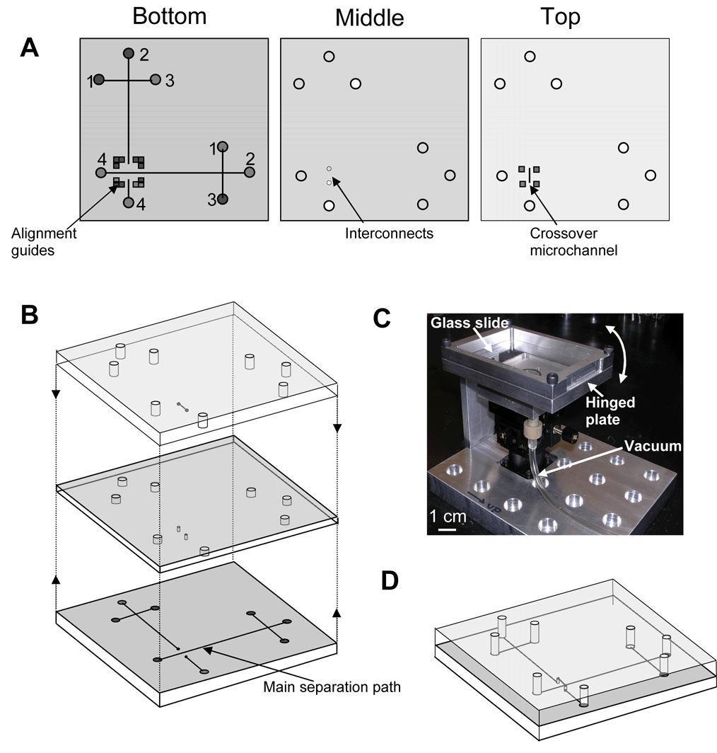
A schematic of the microchip layout is shown in Figure 1A. In our three-layer design, fluidic manifolds are obtained by aligning the top and bottom microchannel-containing layers with the interconnecting through-holes in the middle piece (Figure 1B). The bottom layer has features for two independent electrophoretic systems positioned perpendicular to each other. The main separation path is defined in the bottom layer, and most of the second separation channel is also patterned on the bottom piece, but this structure overpasses the main fluidic path via through-holes bridged with a microchannel in the lower surface of the top layer. Channel linewidths were 40 µm, depths were 30 µm, lengths from reservoirs 1–3 to the injection intersection were 0.5 cm, and the separation channel was 2.5-cm long from the injection region to reservoir 4. The layouts for the bottom and top masks included marks for alignment of the substrates during the bonding step.
Figure 1.
(A) Schematic of the three layers for the fabrication of microchannels in multilayer microdevices. Reservoirs are: (1) analyte, (2) buffer, (3) injection waste, and (4) waste. (B) Exploded view of the three layers. (C) Photograph of the alignment and bonding station. (D) Schematic of a completed microchip formed by successive alignment and bonding of the individual layers. A final device is 4 cm on each side and 4.5 mm tall.
Silicon template preparation
Two photomasks with the features of the bottom and top layers in Figure 1A were drawn using mask layout software (WieWeb) and converted to chromium-coated 5” glass plates using an Electromask TRE Cris-Cross Pattern Generator (Woodland Hills, CA). The features in the mask were then transferred to a silicon template using conventional photolithography and wet chemical etching as described previously.40
Substrate imprinting and reservoir fabrication
Using a procedure reported by Locascio et al.,41 we embossed the elevated features in the silicon template into 1/16-in-thick PMMA substrates (Acrylite OP-3, Cyro, Rockaway, NJ) in a convection oven at 140 °C. We affixed a microscope slide to the back of the template to reinforce it to avoid breakage during imprinting. To prevent the Si template from sticking to the PMMA, we sprayed the surface with silicone lubricant (Stoner, Quarryville, PA) before imprinting the substrates. A CO2 laser cutter (C-200, Universal Laser Systems, Scottsdale, AZ) was used to create 2-mm-diameter reservoirs in the middle and top layers for sample and buffer loading. Finally, two 280-µm-diameter through-holes were made in the middle layer to serve as interconnects.
Filling with sacrificial material
The main fluidic path in the bottom layer was filled with PCSL using the approach reported by Kelly et al.36 Filling non-continuous channels in the bottom layer, interconnecting holes in the middle piece and the crossover channel in the top layer required a modified approach. To deposit sacrificial material in discontinuous channels, solid paraffin wax was placed in the patterned reservoir area at one end of each channel. Then, the substrate was placed on a hotplate at 85°C to melt the sacrificial material and fill the microchannels by capillary action. To avoid overflow of sacrificial material, the amount of paraffin used in this step was selected to cover ~50% of the reservoir area. To fill the crossover microchannels, which did not have patterned reservoir areas at either end, an opening the approximate length of the microchannel was defined on a piece of adhesive tape using the laser cutting system. Then, the surface was covered with the patterned tape, aligning the opening with the microchannel underneath. After this, a small piece of solid paraffin wax was placed on top of the tape and melted to fill the microchannel. Through-holes in the middle layer were also filled with PCSL using this patterned adhesive tape approach.
Alignment and solvent-assisted bonding
Individual layers were aligned as shown in Figure 1B. We designed and assembled an alignment and bonding station using translation and rotation stages (Melles Griot, Carlsbad, CA) integrated in a custom-machined stand (Figure 1C). The station was designed to allow alignment and bonding steps to be performed sequentially by means of three moving parts: (1) a lower x-y-z translation stage (resolution: 1.5 µm), (2) a rotating plate attached on top of the translation stage (angular resolution: 5′), and (3) a microscope slide attached to a top hinged plate, which could be lifted or lowered.
For alignment, the bottom PMMA substrate with PCSL-filled microchannels was held in place on the rotating plate by vacuum. Next, the middle layer was reversibly attached to the microscope slide on the hinged plate using a ~100-µm-thick PDMS film (Sylgard 184, Dow Corning, Midland, MI). Following this, the aligner was placed under a Leica semiconductor inspection microscope (Wetzlar, Germany), and the interconnects in the middle piece were aligned with the two ends of the discontinuous microchannel in the bottom layer. Once the two pieces were aligned the hinged plate was lifted, and 280 µL of acetonitrile were spread on the upper surface of the bottom substrate. Finally, the hinged plate was lowered quickly, and the two layers were held together for 2 min to effect bonding. This sequence of alignment and bonding steps was repeated to seal the top substrate and obtain a fluidic routing manifold with independent crossing microchannels (Figure 1D).
Microdevice Characterization
We evaluated bonding strength, fluid flow in the crossover channel, fluidic integrity, and electrical independence of the flow paths in PCSL-fabricated multilayer microdevices. For these studies a modified microchip was fabricated in which reservoirs 1 and 3 were eliminated in the crossover channel and the spacing between reservoirs 2 and 4 was decreased to 1.5 cm, with either a 5.0 or 0.8 mm gap for the crossover. Bonding strength was determined by affixing Nanoport reservoirs (Upchurch Scientific, Oak Harbor, WA) on top of the openings at both ends of the crossover channel. After filling the main path with orange dye solution and the crossover with green dye, one Nanoport was capped while the other was connected via appropriate fittings to a N2 cylinder at various pressures, and the microdevices were inspected for solution leaks or delamination of the layers. The colored solutions facilitated visual inspection and easy determination of any leaks. The ability of the devices to handle fluid flow in both channels was tested by filling with buffer solution and examining for bubbles inside the microchannels and the crossover section. Complete filling of the crossover channel was verified by measuring the current as a function of applied voltage. We also studied the electrical independence of the flow paths by taking current measurements under applied voltages in the separation channel while various potentials were applied in the crossing channel.
Electrophoretic Analysis of Amino Acids
We tested the ability of our PCSL-fabricated multilayer microdevices to perform μCE. In addition, we studied the effects of both pressure and potential applied in the crossover on the separation performance of fluorescently labeled amino acids dissolved in 10 mM carbonate buffer, pH 9.2. Each amino acid was tagged using FITC as described previously.36 Microchannels and reservoirs were filled with buffer, and 15 µL of sample were added to reservoir 1. To reduce electroosmotic flow, 0.5% (w/v) hydroxypropyl cellulose (average MW 100 kDa, Sigma-Aldrich) was added to the running buffer.42 Sample was loaded using “pinched” injection43 for 20 s with +1.0 kV applied at reservoir 3, while keeping the other reservoirs grounded. For separation, reservoir 2 was grounded, reservoirs 1 and 3 were held at +1.0 kV and a potential of +3.5 kV was applied at reservoir 4. Separated amino acids were detected by laser-induced fluorescence using the 488-nm line from an air-cooled Ar ion laser, as described before.40 Briefly, we focused the laser ~800 µm from the end of the main separation path using a 20x, 0.45 NA objective. Fluorescence was collected with the same objective and detected at a photomultiplier tube after spectral and spatial filtering.
Fluidic integrity during separation was determined by filling the crossover with 0.5 µM fluorescein solution and detecting a μCE separation (in the main path) of two amino acids at a point 2 mm before and 2 mm after the crossover channel. Additionally, we studied the effect of pressurized buffer flow in the crossover on the separation of FITC-labeled amino acids in the main path. Finally, electrical independence during separation was evaluated by applying a potential along the crossover channel and monitoring its effect on μCE of FITC-labeled amino acids in the main path.
RESULTS AND DISCUSSION
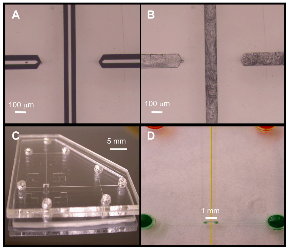
Figure 2A–B shows pictures of the crossover region of an imprinted PMMA microdevice before and after filling the channels with PCSL. By flowing the sacrificial material into the microchannels by using capillary action as opposed to vacuum, we were able to obtain well-filled features without PCSL deposition outside the microchannels.36 Figure 2C shows a photograph of a completed PCSL-fabricated multilayer microdevice with a 0.8-mm-long crossover.
Figure 2.
Microdevice photographs. (A) Image of the crossover region of an imprinted device showing two channel ends. (B) Photograph of the crossover area in the same device after filling with sacrificial material. (C) Photo of a PCSL-fabricated multilayer microdevice with an 0.8-mm-long microchannel crossing over the main separation path. (D) Close-up picture of a crossover in a multilayer microdevice; channels have been filled with colored dye solution to enhance contrast.
During each bonding step, the non-bonding sides of the substrates were covered with masking tape to prevent solvent from contacting the device exterior. In multilayer systems with interconnecting channels, alignment between layers is crucial to ensure fluidic continuity. Although the translational resolution of the x-y-z stage in the alignment station was 1.5 µm, our alignment precision was 26 µm (RSD = 3.5%, n = 10). We attribute this experimental variation to positioning uncertainty in the hinged plate. However, given the larger diameter of the interconnects (280 µm) relative to the microchannels, we were readily able to obtain adequate fluidic continuity between microchannels and interconnects. Ideally, the crossover channel should be as short as possible. The gap between the two ends of the crossover in Figure 2A is ~600 µm; however, laser cutting of through-holes was problematic with this spacing. An 800-µm gap enabled robust crossover fabrication and was the shortest distance for which reliable results were obtained. The volume of these crossover channels was ~0.45 nL, corresponding to <0.4% of the total crossover volume of ~125 nL; the remainder of the crossover volume was contributed by the through-holes.
Figure 2D shows a close-up of the crossover region in a multilayer microdevice. The two colored solutions demonstrate independent fluid flow through the microchannels. When the crossover was pressurized at up to 300 psi, no discernable leaks were observed in microchannels and no delamination of PMMA layers occurred; however, seals between the Nanoports and reservoirs typically failed at ~300 psi, hindering our assessment at higher pressures. Should the need arise for greater pressures in crossover channels, it may be possible to evaluate device integrity at higher pressures by creating threaded reservoir openings.36 Importantly, our results demonstrate that robust PMMA multilayer microfluidic devices can be fabricated using PCSLs.
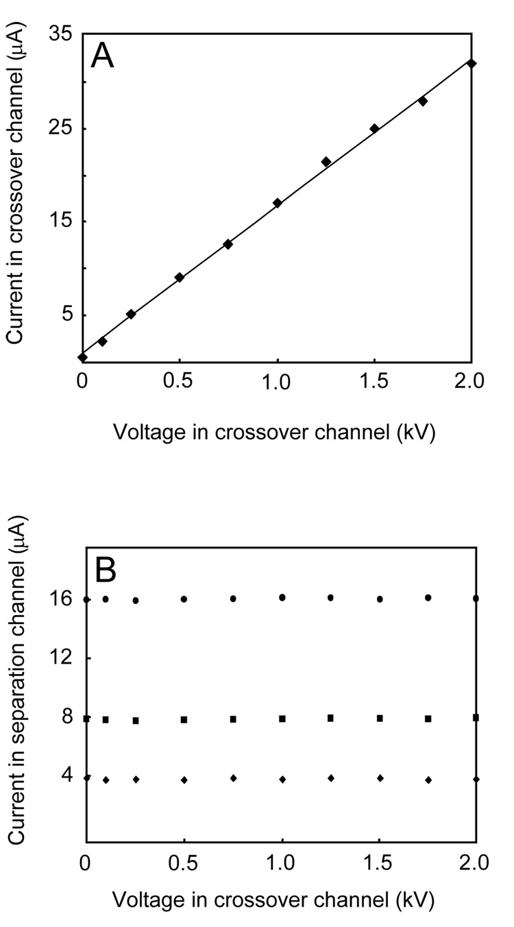
Figure 3A shows a current vs. voltage plot obtained in a crossover channel filled with 10 mM Tris buffer, pH 8.1. The linear relationship observed (r2 = 0.998) indicates that the crossover channel was bubble free and Joule heating was not a problem even at the highest potential applied (2.0 kV). Figure 3B shows current measurements for three applied voltages in the separation channel, in the presence of a range of applied potentials in the crossover channel. For all voltages in the crossover, current measurements in the separation channel at 0.5, 1.0, and 2.0 kV were relatively constant (RSD: 0.2–1.0%). Furthermore, the linear current vs. voltage relationships (r2 = 0.998–0.999) in the separation channel at all applied potentials in the crossover channel indicate the absence of Joule heating. These observations demonstrate that a potential in the crossover channel has no measurable effect on the electrical characteristics of the separation channel.
Figure 3.
Study of the electrical independence of microchannels in PCSL-fabricated multilayer microdevices. (A) Current vs. voltage relationship in the crossover channel (μA = 0.0157V + 0.982; r2 = 0.998) (B) Current in the main separation path at three different potentials (◆: 0.5 kV, ■: 1.0 kV,●: 2.0 kV) in the presence of the indicated voltages on the crossover channel (additional details are in the text).
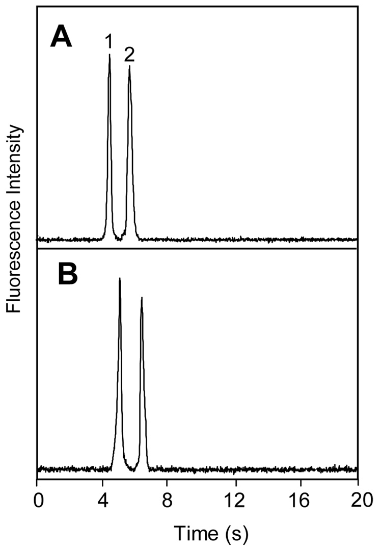
To further confirm the fluidic and electrical independence of the microchannels in our PCSL-fabricated multilayer devices, we studied the effects on μCE of flow and applied potentials in the crossing channel. Separations of amino acids in the main path of multilayer microdevices (e.g.,Figure 4A) were similar to those obtained in standard designs without crossover channels. To study the fluidic independence of the separation and crossover channels, a crossover with a 0.8-mm-long section bridging over the main separation path was filled with 0.5 µM fluorescein solution, and μCE of two FITC-tagged amino acids was performed in the separation channel. Peaks detected 2 mm before (Figure 4A) and 2 mm after (Figure 4B) the crossover channel maintained their shape and baseline integrity. The small shift in migration time was due to detection at different positions in the separation channel.
Figure 4.
Microchip CE of FITC-labeled amino acids for evaluating the fluidic independence of microchannels in multilayer microdevices. Separation and detection were performed in the main (non-crossover) separation path, and the crossover channel was filled with 0.5-µM fluorescein. Detection was (A) 2 mm before and (B) 2 mm after the crossover region. Peaks are: (1) glycine and (2) asparagine.
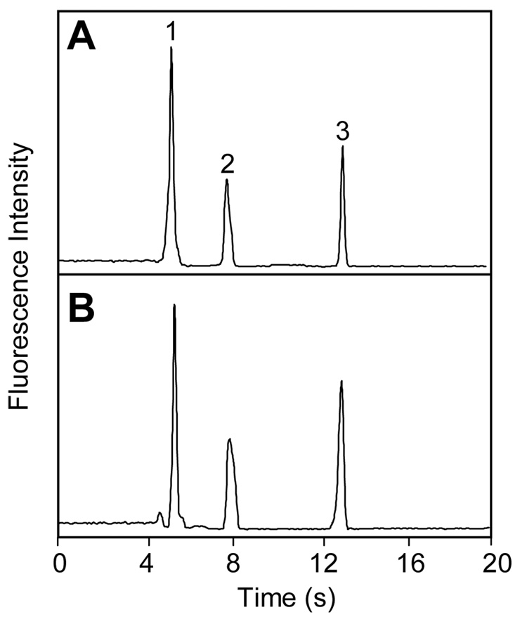
Microchannel fluidic independence was further studied by pumping 10 mM Tris buffer (pH 8.1) through the crossover channel during μCE in the main path. The electrophoretic analysis of three FITC-tagged amino acids in Figure 5A was essentially the same as when the separation was performed with a 1.5 µL/min buffer flow in the crossover channel (Figure 5B). These results clearly demonstrate that microchannels in PCSL-fabricated multilayer devices are fluidically independent.
Figure 5.
Microchip CE of FITC-tagged amino acids in the main separation path in the (A) absence and (B) presence of pressurized 1.5 µL/min buffer flow in the crossover channel. Peaks are: (1) glycine, (2) phenylalanine and (3) arginine.
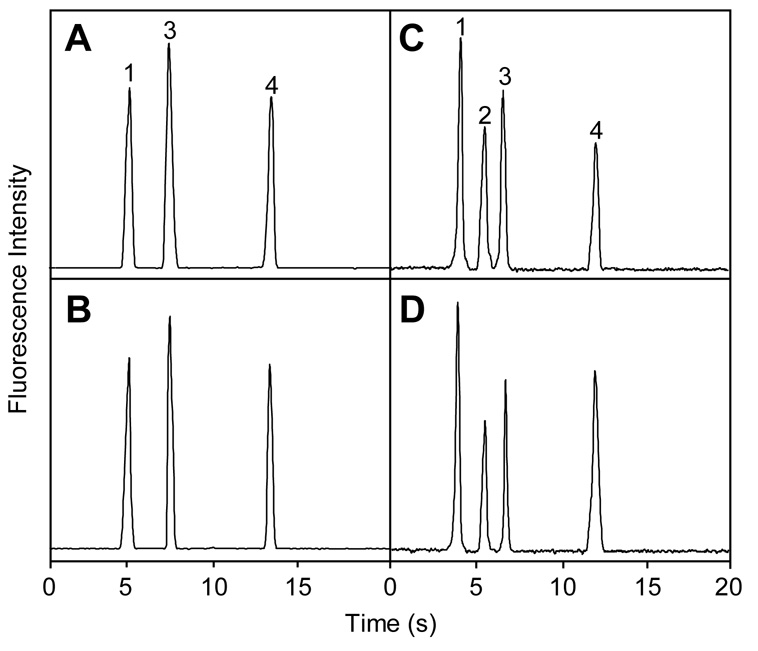
We evaluated the electrical independence of microchannels in our multilayer systems by probing the effects of voltage applied in the crossover channel on separation in the main channel. Figure 6A–B shows μCE analysis of three fluorescently labeled amino acids in a multilayer microdevice with a 5.0-mm-long crossover. Figure 6C–D shows μCE of four fluorescently labeled amino acids in a multilayer microdevice with a 0.8-mm-long crossover. Electropherograms with 250 V/cm applied in the crossover channel (Figure 6B,D) are indistinguishable from those in Figure 6A,C with no applied potential. Separation efficiency for phenylalanine in ten consecutive runs with and without voltage in the crossover was 10,400 theoretical plates (RSD = 3.7%), indicating that the voltage in the crossover has no significant effect on separation efficiency in the main path. These results demonstrate that crossover channels in PCSL-fabricated multilayer systems are electrically independent. This should allow simultaneous microchip separations in both the main fluidic path and a crossover channel, although the large laser-cut through-holes occupy a much greater volume relative to the channels, which currently precludes high-performance μCE in crossover channels. Importantly, even in the present format, applications can be envisioned in which multiple separation paths are maintained in a single layer (so separation quality is sufficient), whereas other fluid manipulations are performed in crossover channels, to reduce the total number of reservoirs needed in a device. For instance, one injection reservoir could be interfaced with many separation channels, by using crossovers only in the injection channels. This would enable the parallel analysis of samples by multiple methods (zone electrophoresis, denaturing or native gel electrophoresis, micellar electrokinetic chromatography, etc.). Moreover, with crossover channels a single sample labeling reservoir could be connected to parallel separation channels (that lack crossovers) to simplify end-column labeling. Crossover volumes could also be reduced; for example, a 250-µm-thick middle layer would decrease the crossover volume sixfold. Alternative hole forming methods could shrink the dead volume further. A heated ~100-µm-diameter wire could form smaller openings in these films than is feasible with laser cutting. Micromachined posts with ~50-µm-diameters could provide through-holes for a middle layer made from a cast or polymerized ~50-µm-thick film; these vias would have a dead volume of ~100 pL, a decrease of three orders of magnitude over the current format. Such volume reductions would enable high-performance separations in channels with crossovers; we are currently exploring this possibility.
Figure 6.
CE analysis of FITC-labeled amino acids for evaluating the electrical independence of microchannels in multilayer microdevices. (A–B) Microchip with a 5.0-mm-long crossover channel. (C–D) Microdevice with a 0.8-mm-long crossover channel. (A,C) Separation and detection in the main separation path; (B,D) same as (A,C) but with 250 V/cm applied in the crossover channel. Peaks are: (1) glycine, (2) asparagine, (3) phenylalanine and (4) arginine.
CONCLUSIONS
We have presented a novel method for fabricating multilayer polymeric microchips using paraffin wax as a phase-changing sacrificial material during solvent bonding. We demonstrated that our crossover microchannels are fluidically and electrically independent; moreover, efficient μCE separations can be performed in the presence of pressure-driven flow or an applied potential in the crossover channel. Our work represents a significant advance in the construction of multilayered microfluidic chips in thermoplastic polymers. Fabrication is easier and faster compared to glass micromachining, and the resulting devices should be suitable for analyses not feasible in previous microchips. PCSL-fabricated multilayer microdevices have potential to increase design flexibility with the integration of additional layers or microchannels for multiplexed and parallel analysis.
ACKNOWLEDGMENTS
This work was supported by the National Institutes of Health (EB006124). Micromachining was performed in the Integrated Microelectronics Laboratory at Brigham Young University. The authors are grateful to the staff in the BYU Department of Chemistry and Biochemistry Instrument Shop and the Precision Machining Laboratory for assistance with electronics hardware and manufacturing the translation stage, respectively.
REFERENCES
- 1.Reyes DR, Iossifidis D, Auroux P-A, Manz A. Anal. Chem. 2002;74:2623–2636. doi: 10.1021/ac0202435. [DOI] [PubMed] [Google Scholar]
- 2.Khandurina J, Guttman A. J. Chromatogr. A. 2002;943:159–183. doi: 10.1016/s0021-9673(01)01451-0. [DOI] [PubMed] [Google Scholar]
- 3.Sia SK, Whitesides GM. Electrophoresis. 2003;24:3563–3576. doi: 10.1002/elps.200305584. [DOI] [PubMed] [Google Scholar]
- 4.Roman GT, Chen Y, Viberg P, Culbertson AH, Culbertson CT. Anal. Bioanal. Chem. 2007;387:9–12. doi: 10.1007/s00216-006-0670-4. [DOI] [PubMed] [Google Scholar]
- 5.Dolnik V, Liu S, Jovanovich S. Electrophoresis. 2000;21:41–54. doi: 10.1002/(SICI)1522-2683(20000101)21:1<41::AID-ELPS41>3.0.CO;2-7. [DOI] [PubMed] [Google Scholar]
- 6.Dolnik V, Liu S. J. Sep. Sci. 2005;28:1994–2009. doi: 10.1002/jssc.200500243. [DOI] [PubMed] [Google Scholar]
- 7.Manz A, Graber N, Widmer HM. Sens. Actuators B. 1990;1:244–248. [Google Scholar]
- 8.Soper SA, Ford SM, Qi S, McCarley RL, Kelly K, Murphy MC. Anal. Chem. 2000;72:642A–651A. doi: 10.1021/ac0029511. [DOI] [PubMed] [Google Scholar]
- 9.Becker H, Locascio LE. Talanta. 2002;56:267–287. doi: 10.1016/s0039-9140(01)00594-x. [DOI] [PubMed] [Google Scholar]
- 10.Boone TD, Fan ZH, Hooper HH, Ricco AJ, Tan H, Williams SJ. Anal. Chem. 2002;74:78A–86A. doi: 10.1021/ac021943c. [DOI] [PubMed] [Google Scholar]
- 11.McDonald JC, Duffy DC, Anderson JR, Chiu DT, Wu H, Schueller OJA, Whitesides GM. Electrophoresis. 2000;21:27–40. doi: 10.1002/(SICI)1522-2683(20000101)21:1<27::AID-ELPS27>3.0.CO;2-C. [DOI] [PubMed] [Google Scholar]
- 12.Qi SZ, Liu X, Ford S, Barrows J, Thomas G, Kelly K, McCandless A, Lian K, Goettert J, Soper SA. Lab Chip. 2002;2:88–95. doi: 10.1039/b200370h. [DOI] [PubMed] [Google Scholar]
- 13.Liu Y, Ganser D, Schneider A, Liu R, Grodzinski P, Kroutchinina N. Anal. Chem. 2001;73:4196–4201. doi: 10.1021/ac010343v. [DOI] [PubMed] [Google Scholar]
- 14.Kameoka J, Craighead HG, Zhang H, Henion J. Anal. Chem. 2001;73:1935–1941. doi: 10.1021/ac001533t. [DOI] [PubMed] [Google Scholar]
- 15.Stachowiak TB, Mair DA, Holden TG, Lee LJ, Svec F, Frechet JMJ. J. Sep. Sci. 2007;30:1088–1093. doi: 10.1002/jssc.200600515. [DOI] [PubMed] [Google Scholar]
- 16.Dittrich PS, Tachikawa K, Manz A. Anal. Chem. 2006;78:3887–3907. doi: 10.1021/ac0605602. [DOI] [PubMed] [Google Scholar]
- 17.Rodriguez I, Spicar-Mihalic P, Kuyper CL, Fiorini GS, Chiu DT. Anal. Chim. Acta. 2003;496:205–215. [Google Scholar]
- 18.Grover WH, Skelley AM, Liu CN, Lagally ET, Mathies RA. Sens. Actuators B. 2003;89:315–323. [Google Scholar]
- 19.Liu J, Hansen C, Quake SR. Anal. Chem. 2003;75:4718–4723. doi: 10.1021/ac0346407. [DOI] [PubMed] [Google Scholar]
- 20.Kim JY, Baek JY, Lee KA, Lee SH. Sens. Actuators A. 2005;119:593–598. [Google Scholar]
- 21.Unger MA, Chou H-P, Thorsen T, Scherer A, Quake SR. Science. 2000;288:113–116. doi: 10.1126/science.288.5463.113. [DOI] [PubMed] [Google Scholar]
- 22.Agirregabiria M, Blanco FJ, Berganzo J, Arroyo MT, Fullaondo A, Mayora K, Ruano-Lopez JM. Lab Chip. 2005;5:545–552. doi: 10.1039/b500519a. [DOI] [PubMed] [Google Scholar]
- 23.Verpoorte EMJ, van der Schoot BH, Jeanneret S, Manz A, Widmer HM, de Rooij NF. J. Micromech. Microeng. 1994;4:246–256. [Google Scholar]
- 24.Daridon A, Fascio V, Lichtenberg J, Wütrich R, Langen H, Verpoorte E, de Rooij NF. Fres. J. Anal. Chem. 2001;371:261–269. doi: 10.1007/s002160101004. [DOI] [PubMed] [Google Scholar]
- 25.Ocvirk G, Munroe M, Tang T, Oleschuk R, Westra K, Harrison DJ. Electrophoresis. 2000;21:107–115. doi: 10.1002/(SICI)1522-2683(20000101)21:1<107::AID-ELPS107>3.0.CO;2-Y. [DOI] [PubMed] [Google Scholar]
- 26.Baltussen E, Sandra P, David F, Janssen H-G, Cramers C. Anal. Chem. 1999;71:5213–5216. [Google Scholar]
- 27.Ren X, Bachman M, Sims C, Li GP, Allbritton N. J. Chromatogr. B. 2001;762:117–125. doi: 10.1016/s0378-4347(01)00327-9. [DOI] [PubMed] [Google Scholar]
- 28.Kuo T-C, Cannon DM, Jr, Chen Y, Tulock JJ, Shannon MA, Sweedler JV, Bohn PW. Anal. Chem. 2003;75:1861–1867. doi: 10.1021/ac025958m. [DOI] [PubMed] [Google Scholar]
- 29.Cannon DM, Jr, Kuo T-C, Bohn PW, Sweedler JV. Anal. Chem. 2003;75:2224–2230. doi: 10.1021/ac020629f. [DOI] [PubMed] [Google Scholar]
- 30.Thorsen T, Maerkl SJ, Quake SR. Science. 2002;298:580–584. doi: 10.1126/science.1076996. [DOI] [PubMed] [Google Scholar]
- 31.Simpson PC, Woolley AT, Mathies RA. Biomed. Microdevices. 1998;1:7–25. [Google Scholar]
- 32.Fettinger JC, Manz A, Lüdi H, Widmer HM. Sens. Actuators B. 1993;17:19–25. [Google Scholar]
- 33.Flachsbart BR, Wong K, Iannacone JM, Abante EN, Vlach RL, Rauchfuss PA, Bohn PW, Sweedler JV, Shannon MA. Lab Chip. 2006;6:667–674. doi: 10.1039/b514300d. [DOI] [PubMed] [Google Scholar]
- 34.Weigl BH, Bardell R, Schulte T, Battrell F, Hayenga J. Biomed. Microdevices. 2001;3:267–274. [Google Scholar]
- 35.Mensing G, Pearce T, Beebe DJ. J. Assoc. Lab. Autom. 2005;10:24–28. [Google Scholar]
- 36.Kelly RT, Pan T, Woolley AT. Anal. Chem. 2005;77:3536–3541. doi: 10.1021/ac0501083. [DOI] [PubMed] [Google Scholar]
- 37.Kelly RT, Li Y, Woolley AT. Anal. Chem. 2006;78:2565–2570. doi: 10.1021/ac0521394. [DOI] [PubMed] [Google Scholar]
- 38.Kelly RT, Woolley AT. J. Sep. Sci. 2005;28:1985–1993. doi: 10.1002/jssc.200500228. [DOI] [PubMed] [Google Scholar]
- 39.Fuentes HV, Woolley AT. Chapter 51. In: Landers JP, editor. Handbook of Capillary and Microchip Electrophoresis and Associated Microtechniques. 3rd Edition. CRC; Boca Raton: 2007. (in press) [Google Scholar]
- 40.Kelly RT, Woolley AT. Anal. Chem. 2003;75:1941–1945. doi: 10.1021/ac0262964. [DOI] [PubMed] [Google Scholar]
- 41.Martynova L, Locascio LE, Gaitan M, Kramer GW, Christensen RG, MacCrehan WA. Anal. Chem. 1997;69:4783–4789. doi: 10.1021/ac970558y. [DOI] [PubMed] [Google Scholar]
- 42.Sanders JC, Breadmore MC, Kwok YC, Horsman KM, Landers JP. Anal. Chem. 2003;75:986–994. doi: 10.1021/ac020425z. [DOI] [PubMed] [Google Scholar]
- 43.Jacobson SC, Hergenröder R, Koutny LB, Warmack RJ, Ramsey JM. Anal. Chem. 1994;66:1107–1113. [Google Scholar]


