

Abstract
Electrically addressable cell traps were integrated with capillary electrophoresis for the analysis of the contents of single adherent cells. Electrodes composed of indium tin oxide were patterned on a glass surface followed by formation of topographical cell traps using 1002F photoresist. Single cells trapped in the holes could be lysed in less than 66 ms by applying a brief electric field (10 ms) across the electrode beneath the cell and the ground electrode placed in the aqueous media above the cell traps. The gas formed during cell lysis remained localized within the cavity formed by the 1002F photoresist. The retention of the gas in the cell trap enabled the cell traps to be coupled to an overlying capillary without blockage of the capillary. Single cells cultured in the traps were loaded with fluorescein and Oregon Green and then electrically lysed. By simultaneous application of an electric field to the capillary, the cell’s contents were loaded into the capillary and electrophoretically separated. Orgeon Green and fluorescein from a single cell were fully resolved in less than two minutes. The use of a single patterned electrode beneath the 1002F cell trap yielded a simple easily fabricated design that was robust when immersed in aqueous solutions. Moreover, the design can easily be scaled up to create arrays of adherent cells for serial analyses using a single capillary or for parallel analysis by mating to an array of capillaries. Enhancing the rate of analysis of single adherent cells would enable a greater understanding of cellular physiology.
Introduction
Chemical cytometry is defined as the use of high-sensitivity analytical tools, such as mass spectrometry, electrochemistry and capillary or microfluidic separation methods, to characterize single cells. Chemical cytometry employing an electrophoretic separation has been used to measure a wide range of cellular properties; for example, quantifying proteins, enumerating mitochondrial properties, identifying carbohydrate synthesizing enzymes and glycosphingolipids, and detecting kinase activation in a single cell.1–10 While the electrophoretic separation of a cell’s contents can be performed on a microfluidic device, to date it has been performed predominantly using capillaries. One reason is that the capillary can be transported to the location in which a cell is growing. This attribute is particularly important since the vast majority of cells grow adherent to a surface and their physiology can be substantially disrupted when the cells are detached from their growth surface. A second reason for the greater application of capillaries in chemical cytometry is the ease of buffer exchange with a capillary. Simply moving the capillary to a new solution vial accomplishes the transfer of the cell from the high salt physiologic buffer to the electrophoretic buffer which is generally low in salt and contains cytotoxic agents such as detergents. However, a major weakness of the capillary-based analysis of single cells is its low throughput, typically less than 20 cells day-1. Strategies with the potential to increase the capillary-based analysis rate of single cells via faster serial analyses or by parallel analysis would broaden the utility of capillary-based cytometry in biomedical research.
Several steps in chemical cytometry using capillary electrophoresis are amenable to improved throughput. Positioning of the capillary over the cell to be lysed and analyzed is often slow, particularly when the cells are randomly located on a surface. Strategies for fast automated lysis are also important; however, the lysis strategy must not interfere with the loading of the cell’s contents into the capillary or the subsequent electrophoretic separation. Finally, decreasing the electrophoretic time and subsequent capillary wash steps could dramatically enhance throughput. Marc and colleagues recently reported a method to use a sheathed flow around a capillary to rapidly move between physiologic and electrophoretic buffers, as well as to eliminate capillary wash steps. 11 This method also possessed the advantage of using short capillaries for electrophoresis and attained an analysis rate of 0.5 cells min-1 for single adherent cells. However, the cells in this strategy were randomly located requiring long times to locate cells between each analysis step. In addition, the method for cell lysis utilized a detergent, making lysis times long and the process difficult to automate. The goal of this work was to demonstrate the feasibility of combining the capillary-based electrophoretic separations with electrical lysis of arrayed cells for faster cell location, as well as improved cell lysis.
The use of electrical fields to induce cell lysis has been well documented.12–14 In most instances, the electrical break down of the outer lipid bilayer of mammalian cells occurs at field strengths of ≥1 kV cm-1.14–20 Electrical lysis of cells has been accomplished on microchip devices typically using a total voltage across the electrodes from 6 V to 1.4 kV depending on the intra-electrode distance.13,14,16,21–24 When the electric potential of the electrodes surpasses 2.06 V, electrolysis of water occurs, resulting in the formation of gas at the electrode.25 This gas formation can rapidly obstruct a microchannel leading to electrophoretic failure in both microfluidic and capillary-based electrophoresis.22,26 To reduce or eliminate gas generation, many investigators have turned to AC fields or very short pulses of a DC voltage. These strategies eliminate or greatly reduce gas formation and blockage of nearby microchannels. However, for AC fields, the probability of cell lysis is a function of the field strength, field frequency, and the cell type.27 Therefore, it can be difficult to find a common set of AC parameters to efficiently lyse all cell types. In contrast, brief DC pulses producing high field strengths (>10 kV cm-1) result in the breakdown of the plasma membrane of virtually all nucleated cells.28–30 Thus, electrical pulses of millisecond duration may prove to be an effective and robust method of lysing a broad range of cell types while minimizing gas formation.
Numerous methods to pattern cells on microchip formats have been developed, including the use of micro-wells to retain cells.31–40 A variety of materials, such as glass, poly(dimethylsiloxane), photoresist, and poly(ethylene glycol) have been used to fabricate arrays of micro-wells for cell localization.34–41 Rettig and Folch reported an array of micro-wells composed of poly(dimethylsiloxane) with high cell occupancies (>70%) and with the propensity to trap gas.34 The phenomenon of trapped gas in microstructures has been well documented in other fields, such as the micropatterning of living cells on micro pallets.42–45 Arrays of micro wells with the appropriate surface properties have the potential to both pattern cells and trap the residual gas formed during electrical lysis.26,46
The goal of this work was to demonstrate the feasibility of combining the electrical lysis of adherent cells held in micro-wells with capillary-based chemical cytometry. Cell traps or micro-wells composed of two photoresists, SU-8 and 1002F, were evaluated as well as the use of electrodes patterned within the micro-well for cell lysis. The rate of lysis of cells within the micro-wells and the ability of the micro-wells to retain gas generated by the electrode were measured. The cell traps were modeled using finite element analysis to understand how the electric field varied within the trap and in regions adjacent to the trap. Multiple cell traps on a single electrode were fabricated and tested. The cell traps were then coupled to a capillary to determine whether the microstructures could eliminate gas release into the overlying capillary during cell lysis. The ability to couple cell entrapment and lysis in a micro-well with the subsequent separation of the cell’s contents by capillary electrophoresis was also demonstrated.
Experimental
Materials
Pre-cleaned glass slides (75 × 25 × 1 mm) were purchased from Corning Glass Works (Corning, NY, USA). Oregon Green 488 carboxylic acid diacetate (6-isomer) and fluorescein diacetate (mixed isomers) were purchased from Invitrogen (Carlsbad, CA, USA). Tissue culture materials were obtained from Gibco BRL (Gaithersburg, MD, USA). The Sylgard 184 silicone elastomer kit (poly(dimethylsiloxane)) was purchased from Dow Corning (Midland, MI, USA). Shipley 1827 and 1808 photoresist, MF 319 developer, SU-8 photoresist, and SU-8 developer (1-methoxy-2-propyl acetate) were obtained from MicroChem Corp. (Newton, MA, USA). Gamma-butyrolactone was purchased from Sigma—Aldrich (St. Louis, MO, USA), EPON resin 1002F (phenol, 4,4′-(1-ethylethylidene)bis-, polymer with 2,2′-[(1-methylethylidene) bis(4,1-phenyleneoxymethylene bis-[oxirane]) was obtained from Miller-Stephenson (Sylmar, CA, USA). Indium tin oxide-coated glass (75 mm × 25 mm, 8–12 ohms per sq) was purchased from SPI (West×Chester, PA, USA). All other reagents were purchased from Fisher Scientific (Pittsburgh, PA, USA).
Fabrication of cell traps from SU-8 with two underlying electrodes
A titanium (500Å) and gold (2500Å) layer were sequentially deposited on a glass slide with an E-beam evaporator. Shipley 1808 photoresist was spin-coated over the metal layers and then soft baked. The photoresist was then exposed to a collimated UV source (Karl Suss Model MJB3) through an iron oxide mask. After developing with MF 319 developer the glass slides were hard baked. The gold layer was then etched with a potassium iodide solution and the titanium layer was etched with hydrofluoric acid. After the fabrication of the electrodes, an SU-8 layer (20 μm thickness) was spin-coated on the metal/glass surface. The SU-8 was then soft baked, and exposed to a collimated UV source (Karl Suss Model MJB3) through an iron oxide mask. The unpolymerized SU-8 was removed using SU-8 developer. The slides with electrodes and SU-8 cell traps were baked for 30 min in a 95 °C oven.
Fabrication of cell traps from 1002F with one underlying electrode
ITO-coated glass was spin-coated with Shipley 1827 photoresist and then soft baked. The photoresist was exposed to an Oriel UV light (365 & 405 nm), and MF 319 developer was used to remove the unpolymerized photoresist. After baking the glass slides, the electrodes were etched using hydrochloric acid. 1002F photoresist (20 μm thick) was then spin-coated on the glass/electrodes. The 1002F was soft baked, and exposed to MA6 UV light source (365 nm). The upolymerized 1002F was then removed with SU-8 developer and the glass slides with electrodes and 1002F cell traps were then baked for 30 min.
Cell culture
Rat basophilic leukemic (RBL) cells, a mast cell tumor line, were grown at 37 °C and 5% CO2 in Dulbecco’s modified eagle medium (DMEM) supplemented with 10% fetal bovine serum, L-glutamine (584 mg L−1), penicillin (100 units mL−1)and streptomycin (100 μg mL−1). The cells were grown in custom-made chambers. The bottom of the chamber was a 75× 25 mm glass slide. The chamber dimensions were 5 × 50 mm and the walls were composed of poly(dimethylsiloxane). Prior to cell culture, the chambers were washed three times with 1 mL of ECB buffer (NaCl, 135mM; KCl, 5mM; MgCl2,1mM;CaCl2,1 mM; Hepes, 10 mM, pH 7.4). Cells were loaded into the chamber at a density of 100 cells mm−2. After a 15 min incubation, the chamber was slowly tilted 30–45° and the buffer with excess cells (not in cell traps) was removed from the chamber with a pipette. Tissue culture media was added to the chamber and the process repeated three times to insure the removal of all cells not in a cell trap. Sixty percent of the traps were occupied with single cells. The remaining forty percent of the traps were either vacant or possessed multiple cells. However, higher occupancy ratios are possible using the methods described by Folch and colleagues or Toner and collaborators.34,37 Occasionally, cells (∼1 cell per 30 mm2 of surface) were present on the 1002F beween the traps. The chamber with cell traps was then placed in an incubator for 12 h prior to use.
Modeling of the electric field strength
Estimation of the electric field generated in the cell trap was performed using the finite element method (FEM) software from COMSOL (Version 3.3, COMSOL, Burlington, MA, USA). Lagrange quadratic equations were used to generate a two dimensional DC model in a conductive media. The model was comprised of a cell trap (20 μm deep, 30 μm diameter) in the center of the lower boundary. The lower and upper boundaries were 1 mm in length. The distance from the upper to lower boundary was 0.8 mm. The ground electrode was 0.1 mm long and centered along the upper boundary. All of the boundary conditions were nonconductive except for the base of the cell trap, which was held at 100 V potential.
Capillary electrophoresis of cell contents
A capillary (15 cm length, 360 μm O.D., 50 μm I.D.) possessing a surrounding tube or sheath which supplied the electrophoretic buffer was used to separate the contents of single cells as described previously.11 To sample a cell, the inlet end of the capillary was positioned 10–40 μm above the cell just prior to cell lysis. A physiologic buffer solution flowed across the cell to prevent exposure of the cell to electrophoretic buffer. Simultaneously, a voltage (100 V for 10 ms) was applied to the electrode below the cell, the electrophoretic buffer through the sheath was initiated, and a voltage (9 kV, CZE1000R, Spellman, Plainview, NY, USA) was applied across the capillary. Electrophoresis was continued for 2 min during which time the fluorescent analytes (Oregon Green and fluorescein) from the lysed cell passed through the detection window of the capillary. After this time the sheath flow and voltage applied to the capillary were terminated. The capillary inlet was then manually moved to the next cell and the process reinitiated to analyze another cell.
Other experimental parameters were as follows. The composition of the physiologic buffer was ECB cell buffer (NaCl, 135 mM; KCl, 5 mM; MgCl2, 1 mM; CaCl2, 1 mM; Hepes, 10 mM). The electrophoretic buffer was comprised of sodium dodecyl sulfate (20 mM), and sodium tetraborate (10 mM, pH 9.3). The flow rate of the physiologic buffer moving across the cell prior to its lysis was 2 mm s−1. The flow rate of the electrophoretic buffer through the tube surrounding the capillary was 0.7 mm s−1. The total length of the capillary was with a window for fluorescence detection 12 to 14 cm from the inlet. Fluorescence detection was as described previously.11
Cell lysis
A pulse generator (214B, Hewlett Packard, Palo Alto, CA, USA) was used to generate DC pulses. The pulse shape and voltage were measured using an oscilloscope (TDS1002, Tektronix, Richardson, TX, USA) and directed to the electrodes on the glass chip.
Fluorescent image analysis
Images were acquired using an inverted microscope with a camera (XC-ST70, Sony, Park Ridge, NJ, USA) and recorded using a digital video recorder (PVR2000 PCI, Leadtek, Taipei, Taiwan). Image J software from the National Institute of Health (http://rsb.info.nih.gov/ij/) was used to measure the fluorescent image intensities of the recorded images. The background fluorescence was subtracted from all images. See the electronic supplementary information† for the techniques used to culture and load cells with the fluorescent compounds.
Results & discussion
Design and fabrication of traps for fast cell lysis
To facilitate visualization by microscopy, the traps were fabricated on a glass surface and the walls of the traps were composed of the photoresist SU-8. The initial design employed two electrodes to address each cell trap (Fig. S1).† For adequate adhesion of the electrodes, a layer of titanium was initially plated onto the glass followed by a gold layer. The photoresist was then overlaid and patterned to yield the circular cell traps, each with a diameter of 30 μm. This design suffered from multiple weaknesses. The cell traps required precise placement over the electrodes, making alignment difficult and prone to failure. In addition, the electrodes were not transparent, so that portions of the cell could not be viewed. Lastly, when an aqueous solution was placed around the cell traps the SU-8 delaminated from the glass surface over a 2–8 h time period (Fig. S2).† To correct these weaknesses, a new design was developed employing a single electrode at the base of the cell trap (Fig. 1A). The second electrode was placed in the aqueous media surrounding the cell trap and was used as a common ground for both the cell lysis and electrophoretic separations performed in later experiments. This design permitted a rapid fabrication with wide tolerances in alignment. An indium tin oxide (ITO)-coated slide was purchased and regions of the ITO removed leaving electrodes of 0.75 mm width. The cell traps could then be located in any region directly above an electrode, greatly facilitating alignment of the electrode layer and cell-trap layer. In addition, half as many electrodes and corresponding electrical access points were required compared to the initial design. The single patterned electrode at the base of the trap is therefore capable of supporting a higher density of electrically addressable cell traps. To eliminate layer delamination, the SU-8 photoresist was replaced with 1002F photoresist to form the cell traps.47 1002F photoresist has greater adhesion to glass than SU-8 and did not delaminate when exposed to aqueous solutions over several days. An added benefit of the 1002F photoresist is its ten-fold lower fluorescence in the visible wavelengths relative to that of SU-8. An asset of this design is that multiple traps could be fabricated per electrode (Fig. 1B). Therefore, all electrodes will likely address at least one cell, even if the trap occupancy rate by cells is less than 100%. Since this single electrode design was simpler to fabricate and more stable in an aqueous solution than the two-electrode design, the single patterned electrode was used for all subsequent experiments.
Fig. 1.
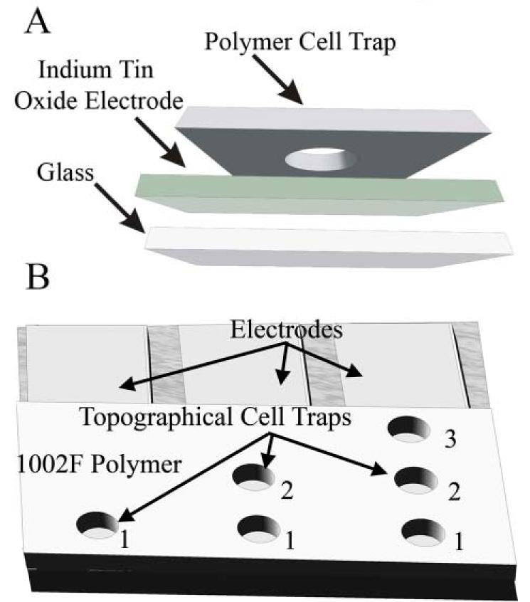
(A) Depiction of the electrode fabrication process. A 1002F cell trap is patterned over an indium tin oxide electrode. (B) Depiction of the 3 cell trap electrode patterns tested with 1, 2, or 3 cell traps per electrode.
Modeling of the electric field in cell traps with a single underlying electrode
A necessary requirement for electrical lysis of cells within the trap is that all regions of the cell (or cell trap) be exposed to similar field strengths so that the entire cell is lysed. In addition, nearby cells on non-activated electrodes should not experience substantial electric fields. To determine whether the cell trap/electrodes could meet these needs, the electric field generated in the cell trap during application of a voltage to the underlying electrode was modeled using finite element methods. The 2-D model possessed a circular cell trap 30 μm in diameter and 20 μm in depth. The electrode at the base of the cell trap was held at 100 V while the ground electrode was placed 0.8 mm above the cell trap and was 0.1 mm in width (Fig. 2). The dimensions were chosen to mimic standard electrode spacing parameters. Similar results were found with models when the electrode size and spacing was varied. The model demonstrates that the electric field in the cell trap is homogeneous except at the uppermost edges of the trap. With a voltage of 100 V at the base of the trap, the field strengths within the trap are in excess of 10 kV cm−1, which is sufficient to lyse all types of mammalian cells. In addition, the field strength falls off rapidly at the top of the cell trap. Within 430 μm of the cell trap, the field strength is less than 0.1 kV cm−1. In addition, non-targeted cells contained in nearby cell traps would be out of the current pathway and thus experience even lower field strengths than if not in the cell trap. Thus in situations where non-targeted cells can not be exposed to electric fields prior to lysis, the cell traps could be patterned as close as 500 μm to each other. It is important to note that the field strength applied to the cell will vary from this idealized model. This is partially due to the difference in conductance between the cell and the physiologic buffer. However, the steady state solution of the electric field across the cell trap provides a useful view of the field strengths generated during lysis.
Fig. 2.
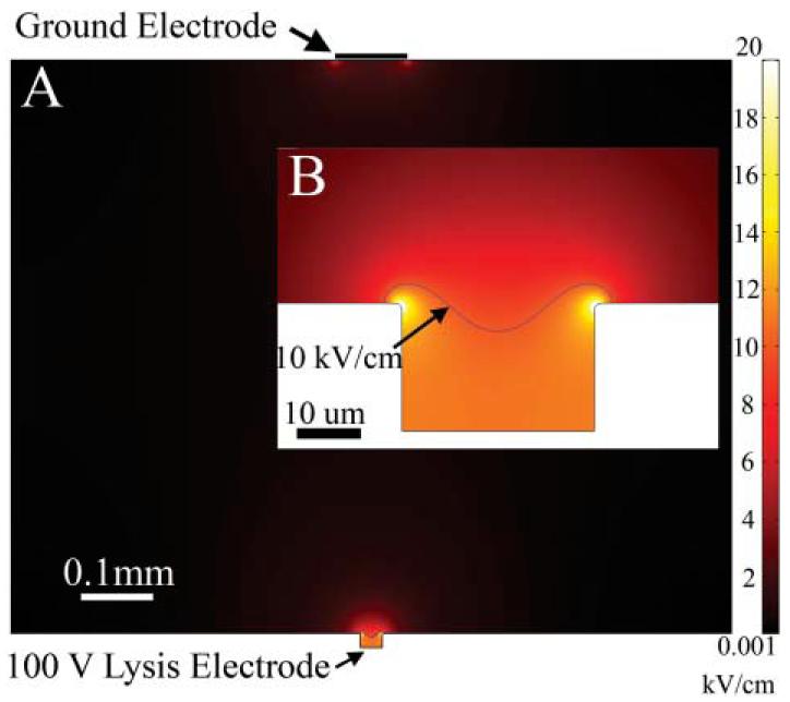
(A) The results of a 2-D finite element model of a cell trap on a single electrode. A conductive media with a 100 V potential between the cell trap electrode and the ground electrode was used. (B) Enlarged view of the cell trap. Note that the majority of the electric field strength generated in the cell trap is greater than 10 kV cm−1.
Measurement of the rate of cell lysis within cell traps
Determining the speed of cell lysis is important in understanding the types of analytes within cells that can be accurately measured using electrophoretic-based methods. For example, the concentrations of second messengers or the phosphorylation state of proteins can change on the time scale of a second.48,49 Cell lysis on this same time scale can result in alterations in these analytes, obscuring their true concentration or state at the moment of lysis. Therefore, accurate measurement of rapidly changing analytes requires cell lysis times of much less than 1 s to avoid the introduction of artifacts. To determine the rate of cell lysis in the traps, RBL cells were loaded into cell traps, cultured for 12 h, and then loaded with a mixture of fluorescein and Oregon Green.
Prior to delivery of the electrical pulse, the cells appeared intact by transmitted light microscopy and were brightly fluorescent (Fig. 3A,B). The cells were then imaged by fluorescence microscopy during and after application of 100 V for 10 ms. Images were acquired at 33 ms intervals and the electrical pulse was applied at random times with respect to the image acquisition times. The time for the loss of the fluorescent dye from the cell was used as a measure of how fast cell lysis occurred. Cells in traps that did not receive a voltage pulse did not exhibit a loss of fluorescence during the imaging time.
Fig. 3.
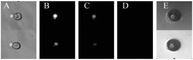
Electrical lysis of single cells in cell traps. (A) Shown is a bright field image of single cells in a cell trap (marked with an asterisk) prior to application of a voltage pulse. The cells were previously loaded with fluorescein and Oregon Green. (B) Shown is a fluorescence image of the cells in panel A. (C) Image of the cells in panel B, 33 ms after application of a voltage pulse (100 V for 10 ms). (D) Image of the cells in panel C after another 33 ms. (E) A bright field image of the gas contained in the cell traps shown in panels A—D following cell lysis.
Within 33 ms of delivery of the voltage, gas was generated at the electrode and the fluorescence of the cell was substantially decreased (Fig. 3C). This suggests that the plasma membrane was breached and that the fluorescent dye had exited from the cell. By 66 ms, the cell was nearly nonfluorescent, indicating nearly complete loss of the dye from the cell. When the cell trap was imaged by transmitted light microscopy following application of the electrical pulse, a large gas bubble occupied the cell traps and remnants of the cell were frequently visible surrounding the cell trap (Fig. 3D,E). It is likely that as the gas was produced at the underlying electrode, the cell was sheared loose from its attachments to the electrode surface and may have been lysed by a combination of electrical and mechanical forces. To quantitate the rate of lysis, the fluorescence of cells in cell traps was measured during and after application of the electrical pulse (10 ms, 100 V). The normalized cell fluorescence was plotted over time for 8 cells (Fig. 4). All cells were lysed by the voltage pulse irrespective of whether the cells were over electrodes with single or multiple traps (Fig. 1B). Every trap was completely filled with a bubble following voltage delivery. The average fluorescence decrease at the 33 ms time point was 40± 20% and 0 ± 1% at the 66 ms time point. The time required for the cell to become nearly nonfluorescent was a measurement of the time for cell lysis plus the time for the dyes to diffuse from the cell into the extracellular solution. Thus, 33–66 ms represents an upper limit for the time to lyse the cell. These data suggest that a very brief (10 ms) increase in the electric field strength was sufficient to lyse cells in less than 33–66 ms, times sufficiently fast for the measurement of almost every cellular analyte. These experiments were performed without capillary electrophoresis in order to demonstrate the role of the electrical pulse in cell lysis. In addition, the multiple cell traps on a single electrode may be of utility in simultaneously loading arrays of capillaries with the contents of single cells
Fig. 4.
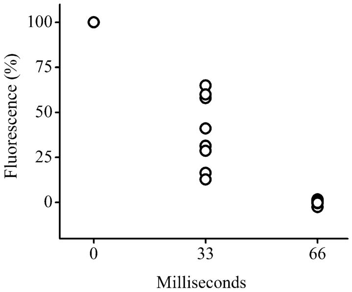
Time course of cell lysis. The fluorescence of the cell as a percentage of that prior to the voltage pulse is shown on the y axis. The voltage pulse was applied at time 0. Data was acquired for eight cells. Each data point at a given time represents the data for one cell.
Integration of cell trap-based lysis with capillary electrophoresis
Han and colleagues demonstrated the ability to lyse cells electrically and then load their contents into a capillary for electrophoretic separation.26 The method, however, was not robust since it employed a tapered, gold-plated capillary as an electrode. The small capillary tip was easily fractured and delamination of the gold layer from the capillary was frequent. To determine whether the cell traps might offer a more robust method of electrical lysis when paired with capillary electrophoresis, the lumen of a capillary was centered 20 μm above a cell trap (Fig. 5A). An electrical pulse (10 ms, 100 V) was delivered to the electrode at the base of the cell trap. Simultaneously, a voltage was applied across the capillary. The outlet end of the capillary was maintained at 9 kV while the inlet of the capillary above the cell trap was held at ground potential. The cell trap was then immediately examined by microscopy. The bubble was retained within the cell trap and did not enter into the capillary (Fig. 5B,C). The ability of the cell traps to retain the gas formed during the voltage pulse was most likely due to the hydrophobicity of the 1002F as well as the geometry of the cell trap. Thus, the surface tension of the overlying aqueous fluid, the surface energy of the 1002F, and the geometry of the trap are such that a lower energy state is attained when air remains in the cavity.50–52 After the voltage pulse and initiation of the electrophoretic voltage, the capillary was translocated away from the cell trap and the current through the capillary monitored for two minutes before the voltage across the capillary was turned off. The current through the capillary remained within 20% of the average capillary current for the 57 traps tested from 3 different arrays. These data suggested that the gas bubble did not enter the capillary when the gas was formed during cell lysis. In a second set of experiments, the capillary remained over the cell trap during the two minute electrophoresis time. In this instance, 2 of 58 tested traps resulted in a greater than 20% current drop through the capillary. Implementation of automated capillary translocation following cell lysis and loading of the cells contents into the capillary may enable the sequential analysis of large numbers of single adherent cells.
Fig. 5.
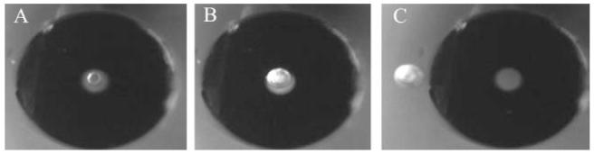
Images of a capillary over a cell in a trap. (A) Before cell lysis. A cell marked by the small arrow is centered beneath the lumen of the capillary. The lumen (50 μm diameter) of the capillary is visualized as the lighter area immediately surrounding the cell. The edge of the outer capillary wall (360 μm diameter) is marked by the large arrow in the lower right hand corner. (B) Image of the capillary and trap in panel shown in (A) but 66 ms after application of a voltage pulse. The cell has been lysed and is no longer present. Instead a gas bubble is seen within in the cell trap. (C) Image of the capillary and trap in panel (B) but the trap has been translocated laterally with respect to the capillary lumen. The arrow marks the gas bubble retained in the trap. The capillary and its lumen are seen to the right of the trap.
Analysis of cells using capillary electrophoresis coupled to cell traps
To determine whether the contents of cells cultured and lysed within a cell trap could be loaded into a capillary and electrophoretically separated, cells were cultured in a trap and then loaded with a mixture of fluorescein and Oregon Green. The lumen of a capillary was positioned above the cell (Fig. 6A). An electrical pulse (10 ms, 100 V) was applied to the electrode below the cell trap. Simultaneously, electrophoretic buffer flow was initiated through a sheath tubing surrounding the capillary11 and a voltage was applied across the capillary to initiate electrophoresis (Fig. 6B). Within two minutes, two fully resolved fluorescent peaks were observed on the electrophoretic trace (Fig. 7). The migration time of the first peak corresponded to that of a standard of fluorescein, while the migration time of the second peak corresponded to that of an Oregon Green standard. Lysis and separation of additional cells yielded similar results (n = 5 cells). The peak area and heights for Oregon Green and fluorescein were similar to that attained previously when the contents of dye-loaded cells were electrophoretically separated following detergent lysis.11 Thus single cells can be rapidly lysed in a cell trap, the cellular contents loaded into an overlying capillary, and Oregon Green and fluorescein from a cell successfully separated and detected.
Fig. 6.
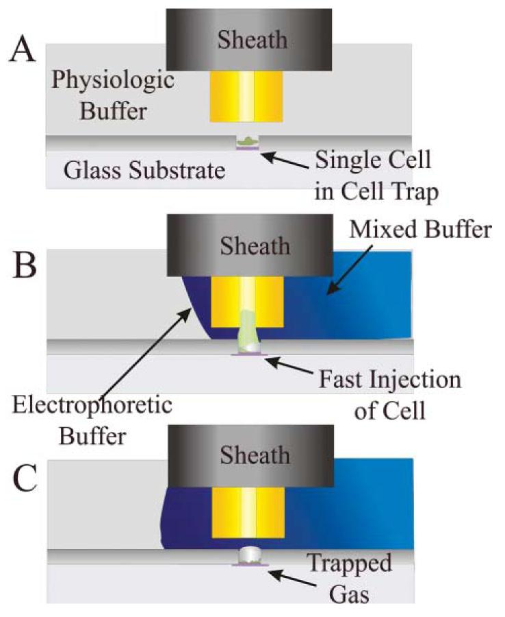
Cell traps coupled with a capillary electrophoresis system. (A) Shown is a schematic of the side view of a capillary electrophoresis system over a cell cultured in a cell trap before lysis of the cell. (B) Shown is the same system in (A) but at the moment of when the electric field is applied to lysis the cell in the cell trap. Simultaneous with cell lysis, the electrophoretic buffer flow is initiated so that the capillary tip and cell are surrounded by electrophoretic buffer. A voltage is also applied across the capillary initiating electroosmotic fluid flow into the capillary. The buffer flows toward an outlet placed in the cell chamber to the right of the capillary. (C) A schematic of the residual bubble in the cell trap is shown following cell lysis. The contents of the cell have moved into the capillary. Please see ref. 11 for a fuller description of capillary electrophoresis using a sheath-flow system to supply electrophoretic buffer.
Fig. 7.
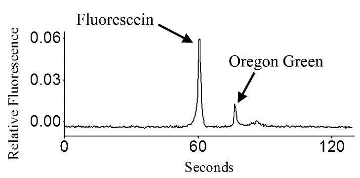
Electrophoretic separation of the contents of a single cell loaded with Oregon Green and fluorescein.
Conclusion
A platform for the electrical lysis of adherent cells followed by the electrophoretic separation of introduced cytoplasmic constituents has been demonstrated. The use of traps enables the patterning of the cells in a regular array as well as the retention of gas formed at the electrode surface during cell lysis. Cell lysis is fast, occurring in 33–66 ms, so that rapidly changing analytes in cells could be measured with this method. The platform could be further enhanced by optimization of the electrical pulse shape and height as well as the geometry of the cell trap and position of the overlying capillary. When serially analyzing cells, the rate of cell lysis is ultimately limited by peak overlap between sequentially lysed cells. For Oregon Green and fluorescein, the width of the peaks plus the time between the peaks was 30 s. Therefore, one cell could be analyzed every 30 s without peak overlap between consecutively lysed cells. This translates into a maximal cellular analysis rate of ∼120 cells h−1. This compares favorably to the current analysis rate of 20 cells day−1 using capillary electrophoresis. Thus, full integration and automation of cell lysis with electrophoretic separation could permit greatly increased rates of analysis of single adherent cells.
Supplementary Material
Acknowledgements
Special thanks to Ruisheng Chang for fabrication of the electrodes and cell traps and to Yuli Wang for scientific advice. This work was supported by NIH grant EB04597. PJM was supported by NIH training grant CA09054.
Footnotes
Notes and references
- 1.Hu S, Lee R, Zhang Z, Krylov SN, Dovichi NJ. J. Chromatogr., B. 2001;752:307–310. doi: 10.1016/s0378-4347(00)00528-4. [DOI] [PubMed] [Google Scholar]
- 2.Zhang Z, Krylov S, Arriaga EA, Polakowski R, Dovichi NJ. Anal. Chem. 2000;72:318–322. doi: 10.1021/ac990694y. [DOI] [PubMed] [Google Scholar]
- 3.Ahmadzadeh H, Thompson LV, Arriaga EA. Anal. Bioanal. Chem. 2006;384:169–174. doi: 10.1007/s00216-005-0171-x. [DOI] [PubMed] [Google Scholar]
- 4.Shoemaker GK, Lorieau J, Lau LH, Gillmor CS, Palcic MM. Anal. Chem. 2005;77:3132–3137. doi: 10.1021/ac0481304. [DOI] [PubMed] [Google Scholar]
- 5.Shoemaker GK, Palcic MM. Anal. Bioanal. Chem. 2007;387:13–15. doi: 10.1007/s00216-006-0641-9. [DOI] [PubMed] [Google Scholar]
- 6.Meredith GD, Sims CE, Soughayer JS, Allbritton NL. Nat. Biotechnol. 2000;18:309–312. doi: 10.1038/73760. [DOI] [PubMed] [Google Scholar]
- 7.Lee CL, Linton J, Soughayer JS, Sims CE, Allbritton NL. Nat. Biotechnol. 1999;17:759–762. doi: 10.1038/11691. [DOI] [PubMed] [Google Scholar]
- 8.Li H, Sims CE, Wu HY, Allbritton NL. Anal. Chem. 2001;73:4625–4631. doi: 10.1021/ac0105235. [DOI] [PubMed] [Google Scholar]
- 9.Li H, Sims CE, Kaluzova M, Stanbridge EJ, Allbritton NL. Biochemistry. 2004;43:1599–1608. doi: 10.1021/bi035597k. [DOI] [PubMed] [Google Scholar]
- 10.Whitmore CD, Hindsgaul O, Palcic MM, Schnaar RL, Dovichi NJ. Anal. Chem. 2007;79:5139–5142. doi: 10.1021/ac070716d. [DOI] [PubMed] [Google Scholar]
- 11.Marc PJ, Sims CE, Allbritton NL. Anal. Chem. 2007;79:9054–9059. doi: 10.1021/ac7017519. [DOI] [PMC free article] [PubMed] [Google Scholar]
- 12.Puc M, Corovic S, Flisar K, Petkovsek M, Nastran J, Miklavcic D. Bioelectrochemistry. 2004;64:113–124. doi: 10.1016/j.bioelechem.2004.04.001. [DOI] [PubMed] [Google Scholar]
- 13.Lu H, Schmidt MA, Jensen KF. Lab Chip. 2005;5:23–29. doi: 10.1039/b406205a. [DOI] [PubMed] [Google Scholar]
- 14.Fox MB, Esveld DC, Valero A, Luttge R, Mastwijk HC, Bartels PV, Van Den Berg A, Boom RM. Anal. Bioanal. Chem. 2006;385:474–485. doi: 10.1007/s00216-006-0327-3. [DOI] [PubMed] [Google Scholar]
- 15.Olofsson J, Nolkrantz K, Ryttsen F, Lambie BA, Weber SG, Orwar O. Curr. Opin. Biotechnol. 2003;14:29–34. doi: 10.1016/s0958-1669(02)00003-4. [DOI] [PubMed] [Google Scholar]
- 16.Lee DW, Cho YH. Sens. Actuators, B. 2007;124:84–89. [Google Scholar]
- 17.He HQ, Chang DC, Lee YK. Bioelectrochemistry. 2007;70:363–368. doi: 10.1016/j.bioelechem.2006.05.008. [DOI] [PubMed] [Google Scholar]
- 18.Weaver JC. IEEE Trans. Dielect. Elect. Insul. 2003;10:754–768. [Google Scholar]
- 19.Weaver JC. IEEE Trans. Plasma Sci. 2000;28:24–33. [Google Scholar]
- 20.Rae JL, Levis RA. Pflugers Arch. 2002;443:664–670. doi: 10.1007/s00424-001-0753-1. [DOI] [PubMed] [Google Scholar]
- 21.Lu KY, Wo AM, Lo YJ, Chen KC, Lin CM, Yang CR. Biosens. Bioelectron. 2006;22:568–574. doi: 10.1016/j.bios.2006.08.009. [DOI] [PubMed] [Google Scholar]
- 22.McClain MA, Culbertson CT, Jacobson SC, Allbritton NL, Sims CE, Ramsey JM. Anal. Chem. 2003;75:5646–5655. doi: 10.1021/ac0346510. [DOI] [PubMed] [Google Scholar]
- 23.Wang HY, Lu C. Chem. Commun. 2006;33:3528–3530. doi: 10.1039/b605722e. [DOI] [PubMed] [Google Scholar]
- 24.Gao J, Yin XF, Fang ZL. Lab Chip. 2004;4:47–52. doi: 10.1039/b310552k. [DOI] [PubMed] [Google Scholar]
- 25.Bard AJ, Faulkner LR. Electrochemical methods: fundamentals and applications. 2nd Wiley; New York: 2001. [Google Scholar]
- 26.Han F, Wang Y, Sims CE, Bachman M, Chang R, Li GP, Allbritton NL. Anal. Chem. 2003;75:3688–3696. doi: 10.1021/ac0341970. [DOI] [PubMed] [Google Scholar]
- 27.Gascoyne PRC, Vykoukal JV. Proc. IEEE. 2004;92:22–42. doi: 10.1109/JPROC.2003.820535. [DOI] [PMC free article] [PubMed] [Google Scholar]
- 28.Agarwal A, Zudans I, Weber EA, Olofsson J, Orwar O, Weber SG. Anal. Chem. 2007;79:3589–3596. doi: 10.1021/ac062049e. [DOI] [PMC free article] [PubMed] [Google Scholar]
- 29.Stewart DA, Gowrishankar IR, Weaver JC. IEEE Trans. Plasma Sci. 2004;32:1696–1708. [Google Scholar]
- 30.Gowrishankar TR, Weaver JC. Biochem. Biophys. Res. Commun. 2006;349:643–653. doi: 10.1016/j.bbrc.2006.08.097. [DOI] [PMC free article] [PubMed] [Google Scholar]
- 31.Falconnet D, Csucs G, Grandin HM, Textor M. Biomaterials. 2006;27:3044–3063. doi: 10.1016/j.biomaterials.2005.12.024. [DOI] [PubMed] [Google Scholar]
- 32.Jung DR, Kapur R, Adams T, Giuliano KA, Mrksich M, Craighead HG, Taylor DL. Crit. Rev. Biotechnol. 2001;21:111–154. doi: 10.1080/20013891081700. [DOI] [PubMed] [Google Scholar]
- 33.Sims CE, Allbritton NL. Lab Chip. 2007;7:423–440. doi: 10.1039/b615235j. [DOI] [PubMed] [Google Scholar]
- 34.Rettig JR, Folch A. Anal. Chem. 2005;77:5628–5634. doi: 10.1021/ac0505977. [DOI] [PubMed] [Google Scholar]
- 35.Chin VI, Taupin P, Sanga S, Scheel J, Gage FH, Bhatia SN. Biotechnol. Bioeng. 2004;88:399–415. doi: 10.1002/bit.20254. [DOI] [PubMed] [Google Scholar]
- 36.Luo C, Li H, Xiong C, Peng X, Kou Q, Chen Y, Ji H, Ouyang Q. Biomed. Microdev. 2007;9:573–578. doi: 10.1007/s10544-007-9066-2. [DOI] [PubMed] [Google Scholar]
- 37.Revzin A, Tompkins RG, Toner M. Langmuir. 2003;19:9855–9862. [Google Scholar]
- 38.Revzin A, Sekine K, Sin A, Tompkins RG, Toner M. Lab Chip. 2005;5:30–37. doi: 10.1039/b405557h. [DOI] [PubMed] [Google Scholar]
- 39.Biran I, Walt DR. Anal. Chem. 2002;74:3046–3054. doi: 10.1021/ac020009e. [DOI] [PubMed] [Google Scholar]
- 40.Deutsch M, Deutsch A, Shirihai O, Hurevich I, Afrimzon E, Shafran Y, Zurgil N. Lab Chip. 2006;6:995–1000. doi: 10.1039/b603961h. [DOI] [PubMed] [Google Scholar]
- 41.Nolkrantz K, Farre C, Hurtig KJ, Rylander P, Orwar O. Anal. Chem. 2002;74:4300–4305. doi: 10.1021/ac025584x. [DOI] [PubMed] [Google Scholar]
- 42.Wang Y, Sims CE, Marc P, Bachman M, Li GP, Allbritton NL. Langmuir. 2006;22:8257–8262. doi: 10.1021/la061602k. [DOI] [PubMed] [Google Scholar]
- 43.Wang Y, Bachman M, Sims CE, Li GP, Allbritton NL. Anal. Chem. 2007;79:2359–2366. doi: 10.1021/ac062180m. [DOI] [PubMed] [Google Scholar]
- 44.Salazar GT, Wang Y, Young G, Bachman M, Sims CE, Li GP, Allbritton NL. Anal. Chem. 2007;79:682–687. doi: 10.1021/ac0615706. [DOI] [PubMed] [Google Scholar]
- 45.Wang Y, Young G, Bachman M, Sims CE, Li GP, Allbritton NL. Anal. Chem. 2007;79:2359–2366. doi: 10.1021/ac062180m. [DOI] [PubMed] [Google Scholar]
- 46.Sims CE, Meredith GD, Krasieva TB, Berns MW, Tromberg BJ, Allbritton NL. Anal. Chem. 1998;70:4570–4577. doi: 10.1021/ac9802269. [DOI] [PubMed] [Google Scholar]
- 47.Pai JH, Wang Y, Salazar GT, Sims CE, Bachman M, Li GP, Allbritton NL. Anal. Chem. 2007;79:8774–8780. doi: 10.1021/ac071528q. [DOI] [PMC free article] [PubMed] [Google Scholar]
- 48.Hennessy BA, Harvey BJ, Healy V. Mol. Cell Endocrinol. 2005;229:39–47. doi: 10.1016/j.mce.2004.10.001. [DOI] [PubMed] [Google Scholar]
- 49.Berridge MJ. Nature. 1993;361:315–325. doi: 10.1038/361315a0. [DOI] [PubMed] [Google Scholar]
- 50.Wang Y, Bachman M, Sims CE, Li GP, Allbritton NL. Anal. Chem. 2007;79:7104–7109. doi: 10.1021/ac070911s. [DOI] [PubMed] [Google Scholar]
- 51.Barbieri L, Wagner E, Hoffmann P. Langmuir. 2007;23:1723–1734. doi: 10.1021/la0617964. [DOI] [PubMed] [Google Scholar]
- 52.Zheng QS, Yu Y, Zhao ZH. Langmuir. 2005;21:12207–12212. doi: 10.1021/la052054y. [DOI] [PubMed] [Google Scholar]
Associated Data
This section collects any data citations, data availability statements, or supplementary materials included in this article.