Abstract
The gradation of porosity in a biomaterial can be very useful for a variety of medical engineering applications such as filtration, bone replacement and implant development. However, the preparation of such structures is not a technologically trivial task and replication methods do not offer an easy solution. In this work, we elucidate the preparation of structures having a graded porosity by electrohydrodynamic spraying, using zirconia (ZrO2), which is widely used in biomedical and other applications. The processes are generic and can be achieved using other bioactive ceramics with similar particle characteristics. The pores on the sprayed surface, the innermost surface and lengthwise cross sections have been analysed in addition to the change in depth of penetration as a function of spraying time. Control of porosity, pore size and depth of penetration has been obtained by varying parameters such as the spraying time, sintering temperature and the sacrificial template. It has been possible to obtain structures with interconnected pore networks of pore size greater than 100 μm as well as scattered pores smaller than 10 μm in size.
Keywords: bioceramic, microstructure, sintering, biomedical, electrohydrodynamic spraying
1. Introduction
Functionally graded materials (FGM) provide the advantage to engineer materials with specific structural, compositional, morphological and mechanical properties (Castillo et al. 2003). In industry, FGM with a porosity gradient are used to overcome the problems caused by severe discontinuities upon the passage from a ceramic to a metallic medium, by providing a gradual transition (Dariel et al. 2001). They are used in applications such as anode-supported electrolyte cells to allow for high electrochemical activity at the interface (Holtappels et al. 2006), preforms for liquid metal infiltration (Corbin et al. 1999) and thermal barrier coatings (Steffens et al. 1999).
As the demand for improved advanced porous implant material is increased, the concept of FGM is being increasingly considered for biomaterials (Castillo et al. 2003). In the case of implants, issues arise due to poor integration of the implant to the tissue surface causing loosening of the implant. In order to overcome this problem, FGM where the level of porosity can be graded have been considered as the ideal solution from a highly porous surface layer (which can interact with the tissue) to a dense core, giving the implant suitable strength to withstand the physiological loadings (Becker & Bolton 1997).
Graded porosity can also find uses in producing artificial spinal cages that could promote the reconstruction of the anterior column after vertebrectomy in tumour and trauma surgery (Lu et al. 2003). The present solutions of carbon fibre and metallic cages do not fuse with the internal environment and give rise to stress shielding, while autologous grafting leads to complications at the donor site, allografts carry the risk of tissue rejection and disease transmission (Lu et al. 2003).
The design of natural bone, how it demonstrates change from a dense stiff external structure of the cortical bone to light and porous cancellous bone on the interior surface, is a perfect example where functional gradation has been used by biological adaptation (Pompe et al. 2003). This type of structure can optimize the material's response to external loading and a similar feature might prove favourable for an artificial bone implant (Pompe et al. 2003). The interest in porosity-graded implants is to enable a new functionality of a spatially guided degradation process and cell ingrowth (Pompe et al. 2003). The graded porosity can also find uses in scaffolds for tissue engineering (Pompe et al. 2003). The minimum pore diameter required for proliferation of osteoblasts, bone ingrowth and angiogenesis (formation of blood vessels) into a scaffold is considered to be 100 μm (Okii et al. 2001) and an interconnected pore network is a necessity.
Unlike producing isotropic ceramic foams, fabricating porous ceramics with graded porosity is more sophisticated and usually requires multiple manufacturing steps (Zeschky et al. 2005). Graded ceramic foams have been produced by compacting ceramic powders with varying amounts of porosity-generating additives, using three-dimensional printing techniques, electrophoretic deposition, stacking tapes with different porosity or by packing ceramic powders to the desired structure and partial sintering of the scaffolds (Zeschky et al. 2005).
The design of porous implant materials with a porosity gradient closely mimicking the bimodal structure of bone (cortical and cancellous) and with a sufficient degree of interconnectivity can be considered a most important challenge (Hing et al. 1999). Production of implants with graded porosity has been attempted with hydroxyapatite (HA) using methods such as tape casting (Pompe et al. 2003) and slip casting (Vaz et al. 1999). The macropores in the outer layers provide access for cells and blood vessels and enhance new bone formation, while the inner dense ceramic structure provides the mechanical stability of the implant. Slip casting produced pores on the external surface that were approximately 100 μm but there was no interconnectivity (Vaz et al. 1999). Although HA is highly bioactive, its mechanical properties are inadequate to be used in load-bearing applications. Osteoimplants with graded porosity have also been manufactured by multiple tape casting using a water-based HA slurry with porosifier (Werner et al. 2002).
The replication method has been used to produce HA structures of graded porosity (Tampieri et al. 2001). Using multiple and differentiated impregnations and using slurries that had HA powders with different crystallinity degrees, a reproduction of cortical and cancellous bone was achieved (Tampieri et al. 2001). Porosity-graded zirconia ceramics have been produced by slurry infiltration with graded pore sizes ranging from 300 to 1000 μm (Miao et al. 2003). These fabrication methods involve multiple steps, and slurry infiltration, also known as dipping/replication method, is known to give rise to poor mechanical properties owing to the central void in the struts as a result of burning out the polymer template (Tulliani et al. 1999).
Research on the possibility of using zirconia as a biomaterial began in the late 1960s (Helmer & Driskell 1969). Introduced as a possible material for the manufacture of ball heads for total hip replacements in the 1980s (Christel et al. 1988), bioinert zirconia still remains popular as a biomaterial for load-bearing applications (Yoshida et al. 2006). Recently, there has been an interest in using zirconia as a scaffold material for tissue engineering applications (Kim et al. 2004; Chen et al. 2006).
Electrospraying has been shown to produce ceramic structures with solid struts (Jayasinghe & Edirisinghe 2004) and better mechanical properties than the dipping method (Chen et al. 2006). This process usually involves two electrodes: the needle and a ground electrode held just below, which can be a ring, plate or point. The needle is connected to a power supply and creates an electric field between the two electrodes. In this method, also known as electrohydrodynamic atomization (EHDA), the ceramic slurry is fed through relatively large needles (diameter of a few hundred micrometres) and has the ability of producing fine droplets that are a few micrometres in size.
This paper describes a novel method of producing ceramic foams with graded porosity. EHDA method has been used to electrospray a zirconia suspension at different time intervals. Control of porosity, pore size and depth of penetration has been obtained by varying the spraying time, the sintering temperature and the sacrificial template. It is the objective to use a ‘one-step’ method to produce foams of graded and interconnected porosity for possible use as substitute bone implants with improved mechanical properties.
2. Experimental procedure
Polyurethane (PU) templates having fully reticulated pore structures of cell size range 740–1040 μm (60 ppi) and 1060–1600 μm (45 ppi) were obtained from Recticel (Corby, UK). The polymer templates were cut into 5 mm×5 mm×5 mm dimensions. For an analysis of depth of penetration and bone structure replication, the 45 ppi foams were cut into 5 mm×5 mm×10 mm dimensions. All templates were dipped in ethanol and excess ethanol was squeezed out prior to being electrosprayed.
2.1 Preparation of zirconia suspension
A 57.1 wt% (approx. 15 vol%) suspension containing zirconia powder (Grade HSY3, supplied by MinChem Limited, Aldershot, UK), with a mean particle size of 0.47 μm and density 6000 kg m−3, was prepared. The zirconia powder was mixed manually for 10 min in ethanol, which contained 1.5 wt% of EFKA 4401 polymeric dispersant (donated by Stort Chemicals, Bishop Stortford, UK), at ambient temperature in a beaker placed in a cold water bath. The suspension was subjected to ultrasonic agitation for 30 min at 200 W input power. Cold water was replenished every 15 min to minimize the evaporation of ethanol. The zirconia content of the suspension was determined by loss-on-ignition on heating up to a temperature of 600°C. The suspension was stored in a plastic bottle and was kept agitated continuously using a roller mixer.
2.2 Equipment set-up for electrospraying and sintering
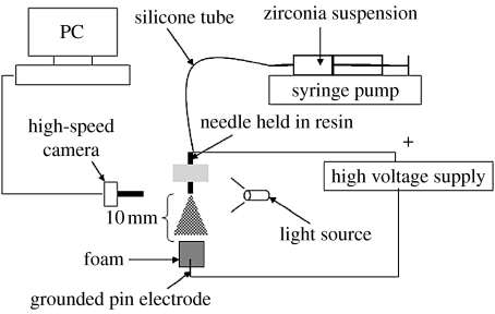
The equipment set-up for electrospraying is shown in figure 1 and a stainless steel needle of inner diameter 510 μm was used. A flow rate of 3.3×10⁻¹⁰ m3 s−1 and voltage in the range of 4.5–5.5 kV were the conditions at which a stable cone-jet mode was established and was observed using a high-speed camera (Weinberger AG, Dietikon, Switzerland). Spraying with the stable cone-jet is important in order to obtain fine near-monodisperse droplets and further details are given in previous work (Jayasinghe & Edirisinghe 2004). The templates were fixed on a pin electrode that was grounded as an attempt to increase the attraction of the zirconia particles towards the foam.
Figure 1.
Experimental set-up used for electrohydrodynamic spraying of the zirconia suspension.
The electrospraying was carried out at ambient temperature. The 60 ppi foams were initially sprayed for 1, 3, 5 and 15 min intervals. The green bodies were allowed to dry at ambient temperature for at least 12 hours prior to sintering. The green bodies were heat treated to 400°C, maintained at that temperature for 1 hour for the pyrolysis of the template to occur and then sintered to a maximum temperature of 1200°C. The sintered samples were maintained at the maximum temperature for 5 hours and then cooled to room temperature. The heating and the cooling rates were 2 and 5°C min−1, respectively.
The same templates (60 ppi) were sprayed for 1, 3, 5 and 7 min intervals under the same conditions, but the maximum sintering temperature was increased to 1400°C. Templates of cell range 1060–1600 μm (45 ppi) were also used, sprayed under the same conditions and sintered at 1400°C. The 45 ppi templates were also cut into 5 mm×5 mm×10 mm samples, then sprayed under the same conditions and sintered at 1400°C.
For bone structure replication experiments, the polymeric template was fixed onto a mechanical rotating device that was also the ground electrode. The 45 ppi templates of dimensions 5 mm×5 mm×10 mm were electrosprayed for 15 min and were sintered to a maximum temperature of 1400°C.
2.3 Sample characterization
The microstructures of the sintered foams were characterized using a Hitachi S-3400N scanning electron microscope (SEM). The samples were sputter coated with gold and were observed using an accelerating voltage of 20 kV.
3. Results and discussion
Initially, a ring was used as the ground electrode and the polymer template was placed below it. The ring was used to disperse the ceramic spray into a larger area in order to produce a more homogeneous coating of the ceramic suspension, but it was observed that the zirconia droplets were collected at the ring and there was no coating observed on the template. Therefore, the experimental set-up was further modified to include a pin that was also the ground electrode and the template was fixed on it. This modification enabled more of the zirconia particles to be attracted towards the template due to the attachment of the ground electrode. The working distance, which is the distance between the exit of the needle and the top surface of the foam, was set at approximately 10 mm as this was the optimized value that enabled good coverage and attraction of the suspension into the foam. Owing to the higher solid loading in the suspension, there were limitations in using finer needles. Using needles of smaller inner diameters makes it feasible to use lower flow rates. Low flow rates are known to produce much finer droplets (Jayasinghe & Edirisinghe 2004). For this 15 vol% ZrO2 suspension, a needle of inner diameter 510 μm was selected, which enabled a flow rate of 3.3×10⁻¹⁰ m3 s−1.
Ethanol was used in the ceramic suspension because it has been known to produce a stable cone-jet that is essential for the EHDA process (Gomez & Tang 1994). Ethanol was also used to dip the polymeric templates prior to spraying and this simple step produced an instant attraction of the zirconia droplets towards the foam and the spraying time was significantly reduced. It was possible to electrospray the PU templates for 1, 3, 5 and 15 min intervals by introducing this step rather than the 2 hours that was the time taken to produce an observable ceramic coating on the template without dipping the template in ethanol. Dipping the foams in ethanol prior to spraying greatly enhanced the efficiency of preparing graded porous structures. This effect could be due to the ethanol improving the attachment of the sprayed ceramic particles by moistening the polymeric surface, in addition to the fact that the ceramic suspension also contains ethanol. The strength of ceramic reticulated foams can be increased by improving the wetting of the PU foam template (Luyten et al. 2005). Polymeric foams have been pretreated with ethanol to improve the wettability of the foam (Mikos et al. 1994; Boccaccini et al. 2003). It has been shown in previous studies that improvements in terms of the degree of infiltration and coating homogeneity have been achieved by pretreatment of a poly(d-lactic acid) (PDLLA) foam with ethanol as it is believed that ethanol tends to reduce the hydrophobicity of the PDLLA foam (Roether et al. 2002). Some work has also been carried out on preparing HA foams using the replication method by presoaking the PU foam templates in ethanol and an improvement in the ceramic coating has been observed (Robinson et al. 2008).
The heat treatment programme was set up based on the results of thermogravimetric analysis carried out on the PU foam templates. It was observed that by 400°C, the PU template pyrolyses and does not leave any residue. Therefore, it is fair to assume that the burnout of the template does not have any effect on the final microstructure upon sintering.
3.1 Depth of penetration
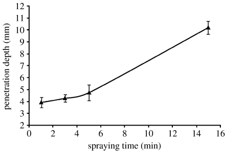
The green bodies electrosprayed for 1, 3, 5 and 15 min intervals using the 60 ppi templates were sintered to a maximum temperature of 1200°C. The samples were measured for their depth of penetration of suspension using a vernier. For each spray time, five samples were measured and a mean value was calculated for the depth of penetration and when the spray time was increased, the suspension penetrated deeper into the foam (figure 2).
Figure 2.
The depth of ceramic suspension penetration as a function of spraying time for the structures sintered at 1200°C (60 ppi templates).
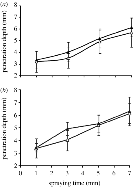
The change in penetration depth was further investigated using different templates having a larger cell range of 1060–1600 μm (45 ppi). It was observed that the 45 ppi templates had better penetration of the ceramic suspension into the foam than in the case of 60 ppi templates as compared in figure 3a. This is expected due to its larger pore size; the fine droplets produced in electrospraying can reach further into the template. When the height of the template was increased, there was a slight increase in the depth of penetration of the ceramic suspension (figure 3b). This is logical since with increased height of the template, the particles can penetrate deeper into the foam. However, it can be seen that the depth of penetration was not doubled by increasing the template height by a factor of 2. This could be due to the thick coating forming on the sprayed surface.
Figure 3.
Comparisons of penetration depth obtained by (a) using different sacrificial templates (open triangles, 60 ppi; filled triangles, 45 ppi) and (b) varying the height of the sacrificial template (45 ppi; open triangles, 5 mm depth; filled triangles, 10 mm depth).
3.2 Microstructural analysis
The green bodies were initially sintered to a maximum temperature of 1200°C. The samples' outer and innermost surfaces were observed using the SEM to investigate the variation in pore size. The innermost surface refers to the surface opposite to the sprayed surface (i.e. the surface furthest away from the sprayed surface). In the case where the template is rotated, the inner surface is the centre of the template, which receives the least amount of direct coating. Therefore, in general, the innermost surface refers to the surface that receives the least direct deposition of the ceramic droplets. The foam structures were not strong enough to be fractured in order to observe the internal cross section in the hope of investigating any variation in pore size. When the sintering temperature was increased to 1400°C, foams prepared were stronger and it was possible to fracture the sintered structures lengthwise to observe their cross sections.
3.2.1 Shape of the sintered structures
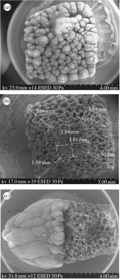
The sprayed surface had a thick layer of ceramic suspension (figure 4a) and the pores were scattered. It was interesting to note an inverted pyramidal structure (a pyramidal crater from the surface downwards) was formed under all sintering conditions and an example is shown in figure 4b. It was expected that pores would get gradually larger in size when deeper into the template as the amount of zirconia particles reaching such locations would be less than that on top of the template, hence resulting in thinner struts and larger pores. However, it was observed that the pores on the innermost surface were again smaller and the struts were relatively thinner than that observed throughout the sintered structure.
Figure 4.
Microstructural features. (a) The electrosprayed surface (the 60 ppi template was electrosprayed for 7 min and sintered at a maximum temperature of 1400°C). (b) An example of inverted pyramid shape observed, gradually narrowing towards the innermost surface (the 60 ppi template was electrosprayed for 3 min and sintered at a maximum temperature of 1400°C). (c) The thick ceramic coating forms a pyramidal shape on top of the foam with increased spraying time (60 ppi template). ESED, environmental secondary electron detector.
The inverted pyramidal shape (figure 4b) could be due to the particle attraction towards the grounded pin electrode. The amount of ceramic particles penetrating deep into the polymeric template is less in comparison with that on the sprayed surface. It is possible that the particles deep within the template get deposited close to the pin electrode. Therefore, due to both the lack of ceramic particles and the attraction towards the pin electrode, in relation to the rest of the foam (especially the sprayed surface), it can be estimated that the innermost layer undergoes most shrinkage. This could be a possible explanation of the smaller pores observed on the innermost layer and the pyramidal shape of the sintered structure. Another factor governing the penetration into the template would be the thick ceramic coating on the sprayed surface preventing the ceramic droplets reaching into the template. This would obviously result in a reduced amount of zirconia particles reaching into the foam resulting in the much smaller pores on the innermost surfaces.
It was also noted that with increased spraying time, the ceramic coating on the sprayed surface became thicker and began to form a pyramid shape structure on top of the foam (figure 4c). In the cone-jet mode in electrospraying, the larger droplets are in the centre of the spray and gradually decrease in size with the distance from the centre (Grigoriev & Edirisinghe 2002). The electrical interaction between highly charged droplets causes a size segregation effect (Hartman et al. 1996). This results in the smaller droplets to be found at the edge of the spray and the large droplets to be found near the spray centre. The bigger droplets in the centre of the foam block the template pores faster than the much finer droplets that deposit on the sides of the foam. With continued spraying, since the pores are blocked in the centre of the template, the ceramic droplets start agglomerating on the surface of the template. With the relatively larger droplets still being deposited in the centre of the foam, at a given time, the thickness of the coating at the centre of the foam will be greater than that on the sides. This will eventually take the shape of a pyramid.
3.2.2 Analysis of the pores
Images of all the sintered samples were studied at three locations—on the sprayed surface, the innermost surface and the cross section. The mean pore size was calculated from approximately 100 measurements for each category. The average pore sizes with their maximum and minimum values have been tabulated in table 1 for the sprayed surface and in table 2 for the innermost surface of the sintered structures.
Table 1.
The pore size values for the sprayed surface (template used is indicated within brackets).
| spray time (min) | average pore size (μm) | s.d. | min. pore size (μm) | max. pore size (μm) |
|---|---|---|---|---|
| 1200°C (60 ppi) | ||||
| 1 | 300 | 90 | 156 | 481 |
| 3 | 16 | 8 | 9 | 42 |
| 5 | 9 | 4 | 4 | 16 |
| 15 | 3 | 1 | 2 | 5 |
| 1400°C (60 ppi) | ||||
| 1 | 226 | 66 | 144 | 451 |
| 3 | 260 | 101 | 71 | 425 |
| 5 | 213 | 61 | 132 | 277 |
| 7 | 66 | 83 | 2 | 240 |
| 1400°C (45 ppi) | ||||
| 1 | 320 | 102 | 115 | 565 |
| 3 | 320 | 70 | 176 | 438 |
| 5 | 10 | 26 | 2 | 108 |
| 7 | 3 | 0.5 | 2 | 4 |
Table 2.
The pore size values for the innermost surface (template used is indicated within brackets).
| spray time (min) | average pore size (μm) | s.d. | min. pore size (μm) | max. pore size (μm) |
|---|---|---|---|---|
| 1200°C (60 ppi) | ||||
| 1 | 222 | 50 | 128 | 346 |
| 3 | 217 | 66 | 86 | 361 |
| 5 | 192 | 85 | 57 | 352 |
| 15 | 277 | 78 | 186 | 530 |
| 1400°C (60 ppi) | ||||
| 1 | 115 | 48 | 42 | 239 |
| 3 | 200 | 60 | 104 | 330 |
| 5 | 168 | 70 | 55 | 354 |
| 7 | 228 | 46 | 138 | 314 |
| 1400°C (45 ppi) | ||||
| 1 | 264 | 84 | 90 | 483 |
| 3 | 218 | 75 | 92 | 408 |
| 5 | 250 | 97 | 120 | 572 |
| 7 | 309 | 103 | 166 | 563 |
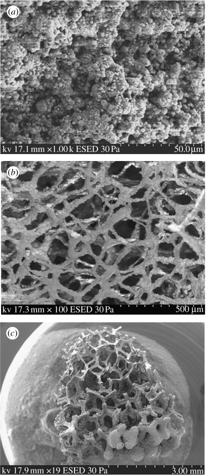
The electrosprayed surface shows a thick coating that increased in thickness as a function of spray time. At higher magnification, micropores in the range of 2–10 μm were observed to be scattered throughout the surface of the structure (figure 5a). It was also observed that the innermost surface had an interconnected pore network with pores greater than 100 μm in size (figure 5b). The lengthwise cross sections of the sintered structures exhibited the presence of pore interconnectivity throughout the structure (figure 5c) and the variation of the pore structure was clearly observed. The interconnected pores towards the centre of the foam were approximately 300 μm in size.
Figure 5.
Microstructural features. (a) Micropores smaller than 10 μm observed on the electrosprayed surface (45 ppi template, electrosprayed for 5 min and sintered at 1400°C). (b) Interconnected pore network on the innermost surface with pores greater than 100 μm (60 ppi template, electrosprayed for 3 min and sintered at 1400°C). (c) Lengthwise cross section showing the variation of pores from the sprayed to the inner surface. Interconnected porosity is present throughout the structure (45 ppi template, electrosprayed for 3 min and sintered at 1400°C). ESED, environmental secondary electron detector.
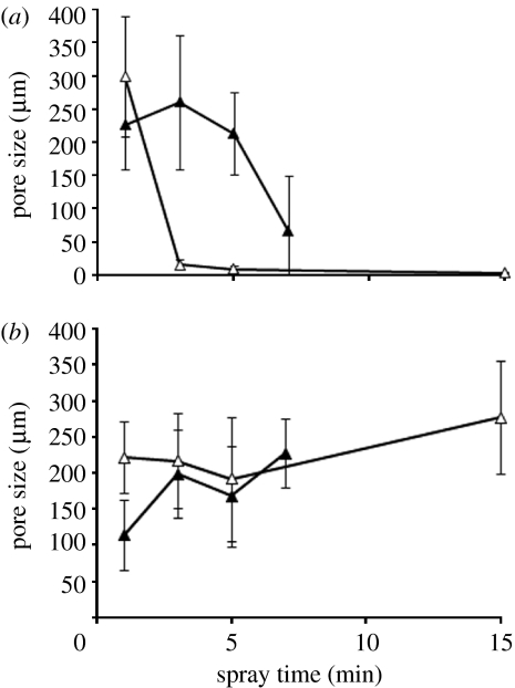
Figure 6 shows the change in average pore size on the sprayed and innermost surfaces as a function of spray time at different sintering temperatures. It can be seen that in general, on the sprayed surface, the pores seem to be larger on the structures that were sintered at a higher temperature (figure 6a). This result seemed uncharacteristic, as it was expected that with increased sintering, due to higher shrinkage, smaller pores would result. However, it is also important to note that this graph indicates only the mean value, as the pores on the sprayed surface have a very large distribution of very small pores and much larger but scattered pores. This can be seen in table 1 where the minimum and maximum of the pore measurements are tabulated. On the inner surface, the structures sintered at the higher sintering temperature show a smaller pore size in comparison with the structures sintered at 1200°C (figure 6b). This can possibly be related to a higher shrinkage at the higher sintering temperature. This can be further confirmed by the minimum and maximum pore sizes in table 2.
Figure 6.
Variation of pore sizes observed on the (a) sprayed surface and the (b) innermost surface as a function of spray time at different sintering temperatures (60 ppi templates). Open triangles, 1200°C; filled triangles, 1400°C.
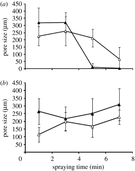
Figure 7a shows the change in pore size on the sprayed surface due to changing the template. At 1 and 3 min spray times, the structures prepared using 45 ppi had larger pore sizes. This is expected as the template used has much larger pores than in 60 ppi. However, with increased spray time, the mean pore size on the sprayed surface of the 45 ppi structures seems to have significantly reduced in comparison with that of 60 ppi. Figure 7b shows a more consistent set of data on the innermost surfaces of the sintered structures using templates having a larger cell range (45 ppi). As expected, the structure prepared using 45 ppi shows a larger mean pore size than the one prepared by using 60 ppi templates, owing to the larger cell range of the former template.
Figure 7.
Variation of pore sizes observed on the (a) sprayed and (b) innermost surfaces as a function of spray time using different templates (open triangles, 60 ppi; filled triangles, 45 ppi).
3.3 Bone structure replication
Lu et al. (2003) have carried out scanning electron microscopy of natural bone to reveal three categories of pores. The first type is the macropores in the inner region of bone, with a large size distribution, and the biggest pore size of approximately 450 μm. The pores have been found to be interconnected, allowing the tissue to infiltrate, enabling body fluid and blood circulation, and allowing the supply of nutrients. The second type contained within the wall of the macropores is of approximately 0.5 μm in diameter and the third, the pores on the cortical bone approximately 10 μm in diameter. They further state that from a biomimetic viewpoint, such bone characteristics should be considered in the preparation of a bone substitute (Lu et al. 2003).
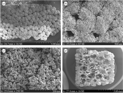
Taking the remarks of Lu et al. (2003) into consideration, the 45 ppi polymeric templates were electrosprayed while being constantly rotated. Figure 8a shows the scanning electron micrographs of the electrosprayed surface of the sintered structure after a spraying time of 15 min. The ceramic coating on the electrosprayed surface was dense and less porous. The pores were of size 130–280 μm, which were scattered with no interconnectivity (figure 8b). The coating at higher magnification (figure 8c) exhibits a rough surface and much smaller pores of size less than 20 μm distributed throughout the outer coating of the structure. With respect to the survival of cells on such a surface, this could enhance the nutrient diffusion by enabling the passage of oxygen molecules and other nutrient molecules.
Figure 8.
Bone-like structure replication (45 ppi templates). (a) Low magnification image of the sprayed surface, (b) larger and scattered pores of diameter 130–280 μm, (c) the coating exhibiting a rough surface consisting of smaller pores less than 20 μm and (d) entire cross section showing the thicker outer layer of zirconia and the more porous interior. SE, secondary electron.
The sintered structure was fractured using a diamond cutting wheel to observe its internal cross section (figure 8d). It shows the cross section with a thick outer layer and a porous and interconnected internal structure. The outer coating was approximately 600–800 μm in thickness. The pore diameter was approximately 150 μm towards the edge of the structure and the pores were observed to gradually increase in size up to approximately 500 μm towards the centre. The interconnected pore network enables efficient nutrient and waste diffusion, thus making electrospraying an efficient method of producing scaffolds with bone-like structure.
In this work, zirconia is used only as an example; in reality, other ceramics such as HA can be used to replicate the structures prepared (Muthutantri et al. 2008). Also methods such as sputtering or evaporating a thin layer of a metallic bond coating onto the polymeric foam to make the template conductive in order to enhance the attraction of the charged ceramic particles to increase the deposition and, hence, further improve the microstructures, are suitable pretreatment strategies. However, the metallic coating should not impair the mechanical properties, toxicity and the bioactivity of the ceramic foam by reacting with it at the sintering temperature, and therefore the selection of a suitable metal has to be carefully carried out after exploratory experiments. Effect of using ceramic suspensions with varied solid content on the pore structure and rotating the foam to increase penetration in addition to reducing the thickness of the outer ceramic layer to produce a more distributed pore structure are being investigated. This fabrication method can also be optimized for producing HA structures of graded porosity or composites of zirconia and HA for a combination of mechanical strength and osteoconductivity.
4. Conclusions
This work has used EHDA to obtain a range of zirconia ceramic structures of graded porosity, crucial for medical engineering and technology development. Fixing the foam on a pin electrode that was also grounded proved to be a successful experimental set-up for obtaining foams of graded porosity. Dipping the polymeric templates in ethanol significantly improved the attraction and adherence of the zirconia particles into the template, reducing the spraying time.
It was expected that the porosity would gradually increase away from the sprayed surface. However, microscopy shows that the pore size increases towards the middle of the foam and then reduces in size in the innermost surfaces of the foam. Micropores smaller than 10 μm were observed on the sprayed surface, while the middle of the foam consisted of approximately 300 μm pores and then were reduced to approximately 100 μm at the inner surface. It was observed that the sintered foams had an inverted pyramid-shaped structure gradually narrowing towards the inner end. With increased spraying time, a pyramid-shaped structure was formed on top of the sprayed surface.
The electrohydrodynamic spraying process has proved to be a very effective and efficient method of fabricating ceramic structures of graded porosity over other methods as it only takes a few minutes and no multiple or repetitive steps are involved in fabrication. The porosity, pore size and depth of penetration can be tailored as desired by changing one or more parameters, such as sintering temperature, spraying time and sacrificial template. The sintered structures excluding the sprayed surface had interconnected pore networks that are desired in scaffolds for bone tissue engineering applications. The porosity-graded foams prepared in this work can find uses as scaffolds that can provide anchorage to osteoblasts in bone tissue engineering applications. If the external coating is not permitted to form a pyramidal shape, it is possible to obtain structures that resemble bone (i.e. dense exterior and porous and interconnected interior). Therefore, by rotating the polymeric template, we have demonstrated the possibility of obtaining bone-like structures, which can be used as a bone substitute, with the porous internal structure providing a framework for cell migration and growth, while the dense exterior provides the mechanical support.
Acknowledgments
EPSRC grant GR/S 97880 and the Royal Society, UK (Brian Mercer Fund) are gratefully acknowledged for funding the research.
References
- Becker B.S, Bolton J.D. Corrosion behaviour and mechanical properties of functionally gradient materials developed for possible hard-tissue applications. J. Mater. Sci. Mater. Med. 1997;8:793–797. doi: 10.1023/A:1018525015421. [DOI] [PubMed] [Google Scholar]
- Boccaccini A.R, Notingher I, Maquet V, Jerome R. Bioresorbable and bioactive composite materials based on polylactide foams filled with and coated by Bioglass® particles for tissue engineering applications. J. Mater. Sci. Mater. Med. 2003;14:443–450. doi: 10.1023/A:1023266902662. [DOI] [PubMed] [Google Scholar]
- Castillo M, Moore J.J, Schowengerdt F.D, Ayers R.A, Zhang X, Umakoshi M, Yi H.C, Guigne J.Y. Effects of gravity on combustion synthesis of functionally graded biomaterials. Adv. Space Res. 2003;32:265–270. doi: 10.1016/S0273-1177(03)90261-4. [DOI] [Google Scholar]
- Chen Q.Z, Boccaccini A.R, Zhang H.B, Wang D.Z, Edirisinghe M.J. Improved mechanical reliability of bone tissue engineering (zirconia) scaffolds by electrospraying. J. Am. Ceram. Soc. 2006;89:1534–1539. doi: 10.1111/j.1551-2916.2006.00935.x. [DOI] [Google Scholar]
- Christel P, Meunier A, Dorlot J.M, Crolet J.M, Witvolet J, Sedel L, Boutin P. Biomechanical compatibility and design of ceramic implants for orthopedic surgery. In: Ducheyne P, Lemons J, editors. Bioceramics: material characteristics versus in vivo behaviour. Annals of New York Academy of Sciences; New York, NY: 1988. pp. 234–256. [DOI] [PubMed] [Google Scholar]
- Corbin S.F, Zhao-Jie X, Henein H, Apte P.S. Functionally graded metal/ceramic composites by tape casting, lamination and infiltration. Mater. Sci. Eng. A. 1999;262:192–203. doi: 10.1016/S0921-5093(98)01019-3. [DOI] [Google Scholar]
- Dariel M.P, Levin L, Frage N. Graded ceramic preforms: various processing approaches. Mater. Chem. Phys. 2001;67:192–198. doi: 10.1016/S0254-0584(00)00438-7. [DOI] [Google Scholar]
- Gomez A, Tang K.Q. Charge and fission of droplets in electrostatic sprays. Phys. Fluids. 1994;6:404–414. doi: 10.1063/1.868037. [DOI] [Google Scholar]
- Grigoriev D.A, Edirisinghe M.J. Evaporation of liquid during cone-jet mode electrospraying. J. Appl. Phys. 2002;91:437–439. doi: 10.1063/1.1420762. [DOI] [Google Scholar]
- Hartman R.P.A, Borra J.-P, Marijnissen J.C.M, Scarlett B. Development of electrohydrodynamic sprays related to space charge effects. J. Aerosol. Sci. 1996;27:S177–S178. doi: 10.1016/0021-8502(96)00161-9. [DOI] [Google Scholar]
- Helmer, J. D. & Driskell, T. D. 1969 Research on bioceramics. In Symp. on Use of Ceramics in Surgical Implants, Clemson University, SC, USA.
- Hing K.A, Best S.M, Bonfield W. Characterization of porous hydroxyapatite. J. Mater. Sci. Mater. Med. 1999;10:135–145. doi: 10.1023/A:1008929305897. [DOI] [PubMed] [Google Scholar]
- Holtappels P, Sorof C, Verbraeken M.C, Rambert S, Vogt U. Preparation of porosity-graded SOFC anode substrates. Fuel Cells. 2006;6:113–116. doi: 10.1002/fuce.200500116. [DOI] [Google Scholar]
- Jayasinghe S.N, Edirisinghe M.J. Electrostatic atomisation of a ceramic suspension. J. Eur. Ceram. Soc. 2004;24:2203–2213. doi: 10.1016/j.jeurceramsoc.2003.07.001. [DOI] [Google Scholar]
- Kim H.W, Kim H.E, Knowles J.C. Hard-tissue-engineered zirconia porous scaffolds with hydroxyapatite sol–gel and slurry coatings. J. Biomed. Mater. Res. B: Appl. Biomater. 2004;70:270–277. doi: 10.1002/jbm.b.30032. [DOI] [PubMed] [Google Scholar]
- Lu W.W, Zhao F, Luk K.D.K, Yin Y.J, Cheung K.M.C, Cheng G.X, Yao K.D, Leong J.C.Y. Controllable porosity hydroxyapatite ceramics as spine cage: fabrication and properties evaluation. J. Mater. Sci. Mater. Med. 2003;14:1039–1046. doi: 10.1023/B:JMSM.0000004000.56814.9e. [DOI] [PubMed] [Google Scholar]
- Luyten J, Thijs I, Vandermeulen W, Mullens S, Wallaeys B, Mortelmans R. Strong ceramic foams from polyurethane templates. Adv. Appl. Ceram. 2005;104:4–8. doi: 10.1179/174367605225010990. [DOI] [Google Scholar]
- Miao X, Hu Y, Liu J, Tio B, Cheang P, Khor K.A. Highly interconnected and functionally graded porous bioceramics. Bioceramics. 2003;15:595–598. [Google Scholar]
- Mikos A.G, Lyman M.D, Freed L.E, Langer R. Wetting of poly(l-lactic acid) and poly(dl-lactic-co-glycolic acid) foams for tissue-culture. Biomaterials. 1994;15:55–58. doi: 10.1016/0142-9612(94)90197-X. [DOI] [PubMed] [Google Scholar]
- Muthutantri A, Huang J, Edirisinghe M. Novel method of preparing hydroxyapatite foams. J. Mater. Sci. Mater. Med. 2008;19:1485–1490. doi: 10.1007/s10856-008-3379-4. [DOI] [PubMed] [Google Scholar]
- Okii N, Nishimura S, Kurisu K, Takeshima Y, Uozumi T. In vivo histological changes occurring in hydroxyapatite cranial reconstruction—case report. Neurol. Med. Chir. 2001;41:100–104. doi: 10.2176/nmc.41.100. [DOI] [PubMed] [Google Scholar]
- Pompe W, Worch H, Epple M, Friess W, Gelinsky M, Greil P, Hempel U, Scharnweber D, Schulte K. Functionally graded materials for biomedical applications. Mater. Sci. Eng. A. 2003;362:40–60. doi: 10.1016/S0921-5093(03)00580-X. [DOI] [Google Scholar]
- Robinson J.H, Best S.M, Ahmad Z, Edirisinghe M.J. The effect of reaction conditions on hydroxyapatite particle morphology and applications to the reticulated foam method of scaffold production. Key Eng. Mater. 2008;361–363:3–6. [Google Scholar]
- Roether J.A, Boccaccini A.R, Hench L.L, Maquet V, Gautier S, Jerome R. Development and in vitro characterisation of novel bioresorbable and bioactive composite materials based on polylactide foams and Bioglass® for tissue engineering applications. Biomaterials. 2002;23:3871–3878. doi: 10.1016/S0142-9612(02)00131-X. [DOI] [PubMed] [Google Scholar]
- Steffens H.-D, Babiaka Z, Gramlicha M. Some aspects of thick thermal barrier coating lifetime prolongation. J. Therm. Spray Technol. 1999;8:517–522. doi: 10.1361/105996399770350197. [DOI] [Google Scholar]
- Tampieri A, Celotti G, Sprio S, Delcogliano A, Franzese S. Porosity-graded hydroxyapatite ceramics to replace natural bone. Biomaterials. 2001;22:1365–1370. doi: 10.1016/S0142-9612(00)00290-8. [DOI] [PubMed] [Google Scholar]
- Tulliani J.M, Montanaro L, Bell T.J, Swain M.V. Semiclosed-cell mullite foams: preparation and macro- and micromechanical characterization. J. Am. Ceram. Soc. 1999;82:961–968. [Google Scholar]
- Vaz L, Lopes A.B, Almeida M. Porosity control of hydroxyapatite implants. J. Mater. Sci. Mater. Med. 1999;10:239–242. doi: 10.1023/A:1008910213166. [DOI] [PubMed] [Google Scholar]
- Werner J, Linner-Krcmar B, Friess W, Greil P. Mechanical properties and in vitro cell compatibility of hydroxyapatite ceramics with graded pore structure. Biomaterials. 2002;23:4285–4294. doi: 10.1016/S0142-9612(02)00191-6. [DOI] [PubMed] [Google Scholar]
- Yoshida K, Hashimoto K, Toda Y, Udagawa S, Kanazawa T. Fabrication of structure-controlled hydroxyapatite/zirconia composite. J. Eur. Ceram. Soc. 2006;26:515–518. doi: 10.1016/j.jeurceramsoc.2005.07.047. [DOI] [Google Scholar]
- Zeschky J, Hofner T, Arnold C, Weissmann R, Bahloul-Hourlier D, Scheffler M, Greil P. Polysilsesquioxane derived ceramic foams with gradient porosity. Acta Mater. 2005;53:927–937. doi: 10.1016/j.actamat.2004.10.039. [DOI] [Google Scholar]


