Abstract
At high magnetic field, B1+ non-uniformity causes undesired inhomogeneity in SNR and image contrast. Parallel RF transmission using tailored 3D k-space trajectory design has been shown to correct for this problem and produce highly uniform in-plane magnetization with good slice selection profile within a relatively short excitation duration. However, at large flip angles the excitation k-space based design method fails. Consequently, several large-flip-angle parallel transmission designs have recently been suggested. In this work, we propose and demonstrate a large-flip-angle parallel excitation design for 90° and 180° spin-echo slice-selective excitations that mitigate severe B1+ inhomogeneity. The method was validated on an 8-channel transmit array at 7T using a water phantom with B1+ inhomogeneity similar to that seen in human brain in vivo. Slice-selective excitations with parallel RF systems offer means to implement conventional high-flip excitation sequences without a severe pulse-duration penalty, even at very high B0 field strengths where large B1+ inhomogeneity is present.
Keywords: Parallel Transmission, High Flip-angle, Slice-selective Excitation, RF Inhomogeneity, Multidimensional Pulse
Introduction
The presence of severe RF excitation field (B1+) inhomogeneity at high magnetic field strength [1; 2] poses a serious challenge for the use of standard slice-selective excitation. The B1+ inhomogeneity leads to non-uniform in-plane excitations resulting in an undesirable inhomogeneity for both Signal-to-Noise Ratio (SNR) and image contrast. Several RF design approaches have been suggested to mitigate this inhomogeneity, including excitation k-space design [3; 4; 5], RF-shimming [6; 7; 8], and adiabatic pulses [9; 10]. In this work, the focus is on extending the current excitation k-space design to higher flip angle, particularly in the context of parallel transmission where significant reduction in RF waveform duration can be achieved compared to conventional single-channel systems.
RF waveforms designed based on the Small-Tip-Angle approximation (STA) [11], along with the appropriate 3D k-space trajectories termed either “fast-kz” or “spokes” trajectories [3; 4; 5], have been shown to be effective in correcting for mild B1+ inhomogeneity, such as that observed at 3T for brain imaging. With these trajectories, slice selection is achieved with a conventional sinc-like RF pulse during each kz traversal (a “spoke”), and in-plane flip-angle inhomogeneity is mitigated by the appropriate choice of the complex-valued amplitude that modulates the RF waveform of the spokes which are positioned at an appropriately chosen set of kx-ky positions. However, with a more severe B1+ field variation, e.g., as observed in brain imaging at 7T, the resulting RF waveform from this design method becomes too lengthy for practical use in conventional sequences with single-channel excitation. For example, in [12], an optimized 30-spoke excitation was designed for slice-selective B1+ mitigation at 7T, resulting in a time-penalty of approximately 30-fold compared to a conventional sinc excitation.
Parallel transmission systems with simultaneous independent control of RF waveforms from multiple channels [13; 14; 15; 16] offer means to accelerate k-space based RF waveforms resulting in shorter excitation duration. With parallel transmission, “spoke”-based trajectories can be use to mitigate highly inhomogeneous B1+ fields, such as are observed in brain imaging at 7T, to produce highly uniform slice-selective excitation with relatively short excitation durations [17; 18; 19; 20]. Nonetheless, a major drawback for the k-space based parallel transmission design is its reliance on the STA approximation, and its failure to adequately perform at large flip angles.
Recently, several promising large-flip-angle design methods for parallel transmission have been proposed [21; 22; 23; 24; 25; 26], with experimental verification performed for 2D spiral excitation in [26], and for spoke-based B1+ mitigation design in [24]. Nonetheless, the spoke-based experiment was only performed under a relatively mild B1+ inhomogeneity constraint with a brain imaging setup at 3T using an oil phantom. In the current work, we describe a new design method for large-flip-angle, spoke-based B1+ mitigation. The method draws on our earlier work [20; 24] and on the work by Xu et al. [26] to provide a much improved B1+ mitigation capability using short duration RF waveforms. The new design method was demonstrated with large-flip-angle parallel excitation for 90° pulses and 180° spin-echo slice-selective pulses on an 8-channel transmit array at 7T in the presence of B1+ inhomogeneity that matches the typical worst-case 3:1 range seen in human brain in vivo.
Theory
Parallel transmission RF design overview
Our goal is to design slice-selective 90° and 180° spin-echo excitations which produce a spatially uniform within-slice flip angle distribution using a highly inhomogeneous multichannel parallel transmission system designed for the head at 7T. We propose a two-stage design to achieve this goal: an initial (linear) approximation design and a (nonlinear) Bloch equation based iterative optimization design. In the initial approximation, the RF and gradient waveforms are designed based on the linear class of large-tip-angle (LCLTA) method [26; 27] with the incorporation of a magnitude least square optimization (MLS) criterion [20; 28] that substantially improves the excitation profile performance. This design method provides a fast algorithm to create large-flip-angle excitation that yields superior performance to the standard STA design. Nonetheless, the LCLTA design utilizes a linear approximation of the nonlinear Bloch equation, resulting in expected imperfections in the excitation profile when the pulses are driven to yield large flip angles. In the second part of the design, a Bloch equation based iterative optimization [24] is used to achieve the ultimate performance through a refinement of the first-stage design. In this optimization, the solution from the initial approximation process is used as an initial guess for an iterative optimization process that loops through a numerical solution of the Bloch equation to provide improvement to the excitation profile. Substantial reduction in computation time during the second design stage is achieved by the application of a local cost function evaluation combined with a spinor-domain based Bloch equation simulation [29].
Initial approximation design
The initial approximation design step utilizes the LCLTA design for parallel transmission proposed Xu et al. [26], with an extension of MLS optimization from [20]. Briefly, and following the notation in [26], the multi-dimensional excitation calculated for L coils using the LCLTA design is written as
| (1) |
where and are the spatial transmit sensitivity profiles and the RF voltage waveforms for coils indexed by l, with * denoting complex conjugation, r the spatial variable, and θ(r) the target flip angle about the x axis after excitation. The term k(t) represents the excitation k-space trajectory defined as , where γ is the gyromagnetic ratio, and G is the gradient, and T is the duration of the gradient waveform. After discretization in space and time, this expression can be written as a matrix equation, θ = Sb, where the matrix S contains (the complex conjugate of) the transmit sensitivity profiles modulated by the Fourier kernel due to the k-space traversal, θ is the target flip angle in space, and the vector b contains (the complex conjugate of) the RF waveforms. With this formulation, the RF pulses can be designed by solving the MLS optimization
| (2) |
Here, the optimization is performed over the region of interest (ROI) implied by a weighting, w, and the term embodies the Tikhonov regularization that is used to control the integrated RF power. The MLS optimization, as represented by |Sb| in Eq. (2), is used instead of the standard Least Square (LS) optimization to limit the optimization to the magnitude of the flip-angle, allowing for flip-angle phase variation (i.e., variation in the axis of rotation). This has been found to achieve substantial gains in excitation magnitude performance over conventional LS optimization with little penalty in the image phase [20].
An inherently refocused spoke-based k-space trajectory similar to the ones described in [30] was used in this work to satisfy the “linear class” assumption for LCLTA design. In designing the spokes trajectory, we made use of the fact that the profiles of the coils do not differ from each other much along the z direction. As a result, we do not expect to achieve any excitation variation or acceleration in z, and simplified the design by restricting the RF pulse shape of all coils to a Hanning-windowed sinc in kz. Consequently we only needed to calculate the amplitude and phase modulation for each of the sinc spokes. This design method have been demonstrated to perform well for low-flip-angle B1+ mitigation on our 8-channel setup at 7T [20].
Bloch equation iterative optimization design
The aim of the iterative optimization is to improve on the excitation profile resulting from the initial linear approximation. The iterative optimization problem is stated as
| (3) |
where mactual is the actual transverse magnetization profile created by the RF pulses obtained via Bloch equation simulation, and mdesired represents the desired transverse magnetization profile. Similar to the initial approximation design, an MLS condition is used to allow spatially-varying in-plane phase and to improve the magnitude design. To simplify the calculation the optimization is again limited to the complex amplitude of the sinc spokes. Furthermore, in this design stage, as part of Eq. (3) a hard limit on the maximum RF voltage is specified to accommodate hardware limits on the maximum voltage amplitude.
Powell optimization [31] is chosen as the method for the iterative optimization of Eq. (3). Similar to Conjugate-gradient methods, the Powell method is a direction-set method where line minimizations are performed successively along a set of directions [31]. However, unlike the conjugate-gradient methods, the gradient or derivative of the cost function is not used in updating this set of directions during the optimization. Without the gradient information, more iterations may be required for the algorithm to converge. Nonetheless, in cases where gradient evaluation is expensive, such as here, Powell optimization can be more efficient than conjugate-gradient search. In using Powell optimization to solve Eq. (3), the initial bases at the start of the optimization are set to be either the real or imaginary part of the amplitude of the sinc spokes, and the line minimizations are performed along the bases in a bounded region that is within the maximum RF voltage constraint.
To improve computational speed, the optimization is tailored to take advantage of the spin domain representation of the RF excitation [29], where “partial” Bloch simulation method is used. The spin domain formulation and the partial Bloch simulation are described below.
In [29], Pauly et al. provide a derivation for the spin domain Bloch simulation where the spin domain matrices, Qi(r), representing the rotation at different excitation time samples are multiplied together to obtain the total rotation, Q(r), due to the applied RF and gradient waveforms. For n time points, the total rotation is represented as
| (4) |
The final magnetization is then calculated by applying the total rotation, Q(r), to the initial magnetization vector. For parallel transmission, an additional step is required during simulation, whereby the contributions from the different RF transmission channels are added vectorially prior to the spin domain matrices calculation.
In deriving the partial Bloch simulation for Powell optimization, the spin domain representation is used to describe the spoke excitation. The total rotation in the spoke excitation can be represented as the product of the spin domain matrices from the various spokes of the RF waveform, or
| (5) |
In Powell optimization, during a line minimization along a particular direction set, the complex amplitudes of only a limited subset of the spokes are allowed to change. Therefore, only the spin domain matrices associated with these spokes will be updated. This observation allows for an efficient calculation of the new total rotation during the line minimization, in which only the spin domain matrices of the modified spokes are recalculated. Once recalculated, these matrices are multiplied together with the matrices from the unchanged spokes to create the new total rotation. This partial Bloch simulation method substantially reduces the calculation time of the line minimization, especially in cases where a large number of spokes are present in the RF waveform.
For a Matlab implementation of the line minimization, the standard ‘fminbnd’ function, which utilizes the golden section algorithm, can be employed. With this function, it was noted that by restricting the number of iterations to approximately five, the calculation time can be reduced significantly without noticeable increase in excitation profile error of the resulting RF pulse.
Further reduction in computation time can be achieved via the appropriate selection of the spatial points to be included in the optimization. Since the time to perform the Bloch simulation scales linearly with the number of spatial points simulated, computation time for the optimization can be minimized by limiting the number of spatial points used in the cost function (Eq. (3)). Nonetheless, with highly inhomogeneous excitation coil profiles in a parallel transmission setup, a dense sample of simulated points are required to provide good control of the resulting in-plane and slice-selection profiles. Empirically, we found that for our eight transmission coil setup with a 17 cm FOV, using a grid of points spaced uniformly 0.8 cm apart in the transverse plane, three equally spaced sections along z within the excited slice provides a good compromise between computation cost and acceptable convergence to the desired profile. In evaluating the cost function (Eq. (3)), the target excitation (mdesired) for the center transverse section is specified to have a value of 1, while for the peripheral sections the average excitation magnitude across the section (at the current state in the optimization) is used. With these target excitation values, excitation inhomogeneity is penalized while allowing for homogenous excitation of a lower value at the peripheral sections to account for slice-selection transition along z.
Variable-rate selective excitation (VERSE)
Variable-rate selective excitation (VERSE) [32] has been widely used to effectively reduce SAR and limit peak RF voltage. In [3], VERSE was used in a single-channel spokes RF design. In [33; 34], extensions of VERSE to multi-channel RF design were proposed for 2D spiral excitation. In this work, VERSE is employed for multi-channel spoke RF design to satisfy system peak RF voltage limitation of 130 V.
When VERSE is employed for parallel transmission it is important that the VERSEd RF waveforms from all the transmission coils are synchronous. To achieve this while avoiding unnecessary increase in pulse duration, each spoke of the RF waveform is VERSEd separately. For each spoke, the sinc pulse with the largest RF voltage is VERSEd to the system peak voltage limit. Subsequently, the other sinc pulses are then VERSEd such that their durations match with that of the first VERSEd sinc pulse.
B0 inhomogeneity correction
The narrow-band nature of the spatially tailored parallel excitation pulses was apparent in [16; 35], where it was shown that B0 inhomogeneity present in standard in vivo brain imaging can have a detrimental effect on the excitation profile. In this work, B0 inhomogeneity correction has been incorporated into the RF design, both in the initial approximation design, and in the Bloch equation iterative optimization design. For the initial approximation design, a procedure similar to [16; 35] is used. For the Bloch iterative optimization design, the B0 inhomogeneity is accounted for by directly incorporating it into the Bloch equation simulation.
Additionally, when the VERSE algorithm is employed, an extra B0 compensation step should be applied to the RF waveforms. In the presence of B0 inhomogeneity, the effect of VERSE on the RF waveforms' off-resonance behavior can lead to significant excitation artifact. To mitigate this VERSE-induced excitation artifact, the RF waveforms are re-optimized via the Bloch iterative optimization (post-VERSE). To ensure good convergence of this re-optimization, the RF waveforms should initially be VERSEd to a voltage level below that of the system limit (we used a margin of ∼10% in this work). This will provide the re-optimization with a better working voltage range (up to the system voltage limit).
Methods
System hardware
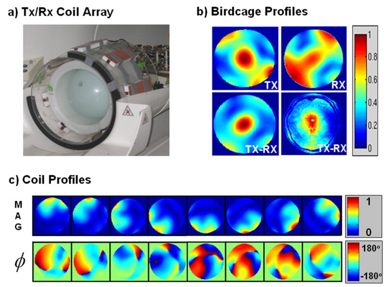
Experiments were performed on a Siemens prototype 7T Magnetom scanner (Erlangen, Germany), equipped with an 8-channel transmit system, with maximum gradient amplitude of 40 mT/m and slew rate of 200 T/m/s. An 8-channel stripline coil array was used for transmit and receive [36]. The RF array was built around a 28-cm diameter acrylic tube (Figure 1a) and was driven through a transmit-receive switch at each of the 8 rungs. All measurements were performed in a 17-cm diameter doped water phantom, containing 1.25grams/liter of Nickel Sulfate and 5 grams/liter of Sodium Chloride. The Birdcage reception mode of the RF array was used for all image acquisitions, whereby the complex data from the eight individual receive channels were phased with an incremental phase of 45° and were added to mimic reception with the traditional birdcage coil. A cylindrical loading ring was used to reduce the amount of B1 inhomogeneity observed in the spherical water phantom to a similar level observed in human in vivo imaging. Figure 1b), shows the transmit-receive (TX-RX) birdcage image for in vivo and for the water phantom with loading ring, where the peak-to-trough signal ratio is ∼9 and ∼8.5 for in vivo and water phantom respectively (this includes a transmit-side magnitude inhomogeneity of ∼3:1). Analogous to the Birdcage reception, the Birdcage transmission employed for the excitation was created by driving the coil elements of the RF array with the same magnitude but with a fixed phase relationship of 45° increment from one element to the next.
Figure 1.
(a) Eight-channel transmit/receive stripline coil array that was used in this work. (b) The estimated transmit (TX) and receive (RX) profiles and the transmit-received image (TX-RX) of the birdcage mode of the array for a water-filled spherical phantom surrounded by a ‘loading ring’ to match the excitation inhomogeneity to that observed for in vivo brain imaging at 7T. Also shown (bottom right) is an in vivo transmit-receive image (TX-RX) of the birdcage mode of the array with similar inhomogeneity to the phantom transmit-received image. (c) Estimated magnitude (normalized units) and phase (degrees) of the transmission coil profiles.
RF design
To demonstrate the capability of the proposed high-flip-angle design method, the technique was used to obtain parallel RF waveforms for 1-cm thick slice-selective 90° and 180° spin-echo excitation sequences that mitigate for B1+ inhomogeneity at 7T. In the spin-echo sequence, to create a sharp slice selection, a 90° excitation with a 2-cm slice thickness, followed by a spin-echo pulse with a 1-cm slice thickness was used to ensure full excitation of the ±0.5 cm slice prior to the application of the 180° spin-echo excitation. Due to the design improvement from the MLS criteria, RF waveforms containing only three spokes were adequate for both the 90° and 180° excitations to achieve excellent B1+ mitigation. Sinc sub-pulses with time-bandwidth-product of 4 were used, and the gradient trajectories were designed for maximum gradient amplitude and slew rate limits of 15 mT/m and 150 T/m/s, resulting in pre-VERSE pulse durations of 3.31 and 2.06 ms for 1-cm and 2-cm thick excitations respectively. The post-VERSE pulse durations for the 1-cm thick 90° and 180° excitations were 4.4 and 5.6 ms while the duration for the 2-cm thick 90° excitation was 3.26 ms. The maximum voltage level used for VERSEing was 120 V, whereas the system voltage limit used for the RF waveforms re-optimization was 130 V.
For each RF pulse design, the appropriate Tikhonov regularization parameter value (β) providing a good tradeoff between excitation error and RF power was empirically determined via the L-curve plot [37].
Simulation comparison of RF design methods
To compare the performance of the proposed RF design method with other design techniques, simulation results of the 1-cm thick 180° spin-echo excitation profile achieved via the proposed method is judged against those obtained via the LCLTA design [26], and the modified LCLTA design with the MLS optimization criterion (i.e., the initial approximation design in our proposed method). Comparison of the required RF energy and maximum RF voltage for these designs are also provided.
B1+ mapping
Quantitative B1+ maps (e.g. in units of μT/V) are required for flip-angle specific RF excitation design. In this work, we employed an efficient B1+ mapping technique described in [38] to estimate the B1+ maps of the coil elements in the RF array. The resulting maps are shown in Figure 1c. With this mapping technique, an estimation for the spin-density weighted birdcage receive profile , is also obtained. This is shown as part of Figure 1b. This receive profile estimation is used in dividing the reconstructed image in the parallel excitation experiments to obtain the excitation profiles.
Experiments and quantification
For high-flip-angle excitations both the spatial uniformity and the flip-angle of the excitation pulses were quantified. The uniformity of the excitation profiles was quantified by the normalized standard deviation, σ, of the pixels in the field of excitation (FOX), as well as by the fraction of pixels in the FOX that are within +/-10% and +/-20% ranges around the mean in-slice signal value. In quantifying the flip-angle, different methods were used for the 90° and the 180° spin-echo excitations.
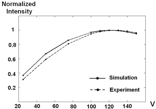
For the 90° excitation, the RF waveforms were transmitted at a series of RF voltage levels, and the average in-plane excitation intensity at each level was recorded and compared against those predicted by simulation. The simulated intensities used for the comparison were obtained by first performing the Bloch simulation on the RF waveforms at a series of voltages to acquire the flip-angle distribution, θ(x, y, V). This distribution is then use to calculate the image intensity (inside the FOX) via the standard GRE signal equation
| (6) |
The image intensity inside the FOX is then averaged to create the average excitation intensities used for the comparison.
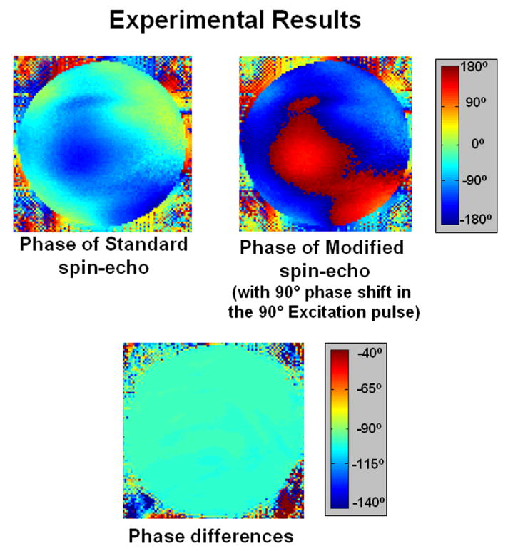
To validate the 180° pulse in the spin-echo sequence, we measured the performance of the phase reversal effect of the pulse. For this task, data acquired with two spin-echo sequences where the 90° excitation pulses differed in phase by 90° were compared. The phase shift in the excitation pulse should cause the excited transverse magnetization to be shifted in phase by the same amount (i.e., 90°). With the proper application of the 180° pulse, this phase shift should reverse from 90° to -90°. Therefore, by comparing the excitation phase images produced by the two sequences, the efficiency of the phase reversal and echo effect of the 180° pulse can be determined. (The relative phase different between the two images should be -90°.)
The transverse magnetization due to all of the excitation sequences was encoded with a 3D gradient-recalled echo sequence with receive matrix size of 128×128×32 voxels, FOV = 256 mm × 256 mm × 160 mm, spatial resolution = 2 mm × 2 mm × 5 mm, and TR, TE, BW = 1000 ms, 20 ms, 260 Hz/pixel. The excitation profiles were then inferred by dividing the reconstructed image by the estimated spin-density weighted birdcage receive profile, (obtained during the B1+ mapping process).
Results
Experimental 90° excitation
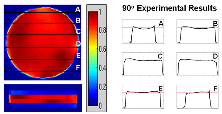
Figure 2 shows the excitation profiles from the 90° excitation, with the in-plane and the slice-selection profiles on the left and the 1D through-slice profiles (A-F) on the right. Excellent in-plane B1+ mitigation and slice selection can be observed. To quantify the performance of the excitation, we note that 96% of the in-slice pixels deviate by less than 10% from the flat magnitude target profile, whereas all in-slice pixels are contained within the 20% bracket. The normalized standard deviation of the in-slice pixels for this excitation is 5.1%.
Figure 2.
Excitation profiles from the 3-spoke 90° excitation, Left: the in-plane and the slice selection profiles, Right: the 1D through-plane profiles along several cuts through the in-plane profile.
Figure 3 shows the normalized average in-plane intensity as a function of peak RF excitation voltage for both simulation and experimental data. Good agreement between the two data sets can be observed, validating the expected flip-angle behavior of the 90° excitation pulse.
Figure 3.
Simulation and experimental data plots of the normalized average in-plane intensity as a function of peak RF voltage for the 3-spoke 90° excitation. Good agreement between the simulation and experimental data can be observed.
Experimental spin-echo excitation
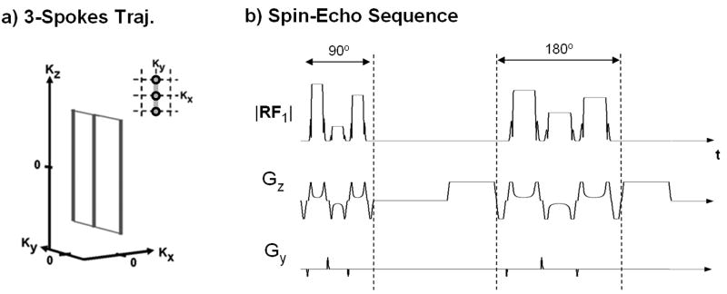
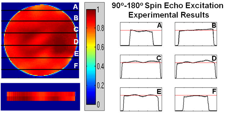
Figure 4(a) illustrates the 3-spokes k-space trajectory employed for both the 90° and the 180° excitations. In this design, the spokes are placed at the center of k-space and at two locations with a distance of 1/FOV in the transverse plane from the center of k-space (where FOV was 20 cm). Figure 4(b) shows the sequence diagram for the VERSEd spin-echo sequence which consist of a 3-spoke 90° and a 3-spoke 180° spin-echo excitation (TE = 20 ms). Shown are the Gz and Gy gradient and RF waveform from one of the transmission coils (coil 1). Also shown are the crusher gradients surrounding the 180° spin-echo. Figure 5 shows the excitation profiles for this spin-echo sequence. Again, excellent in-plane B1+ mitigation and slice selection can be observed. To quantify the performance of this excitation, 92% of the in-slice pixels deviate by less than 10% from the flat target profile, whereas all pixels are contained within the 20% bracket. The standard deviation of the in-plane pixels for this excitation is 6.2%.
Figure 4.
(a) 3-spoke k-space trajectory used for both the 90° and the 180° excitations. (b) The gradient waveforms (Gz and Gy) and RF waveform from one of the excitation coil (coil 1) for the VERSEd spin-echo sequence consisting of a 3-spoke 90° and 180° spin-echo excitations (TE = 20 ms). Also shown are the Gz crusher gradients surrounding the 180° spin-echo.
Figure 5.
Spin-echo excitation profiles, Left: the in-plane and the slice selection profiles, Right: the 1-D though-plane profiles along several cuts through the in-plane profile.
Figure 6 provides a validation of the phase reversal effect of the 180° spin-echo excitation. The phase image obtained from the standard and the modified spin-echo sequences are shown on the top left and right respectively. The relative phase difference image is shown at the bottom of the figure. As expected, a relative phase difference of -90° can be observed throughout the image.
Figure 6.
Top: the phase images obtained from the standard (left) and the modified (right) spin-echo sequences. Bottom: the relative phase difference image, with observed phase difference of -90° as predicted.
Simulation comparison
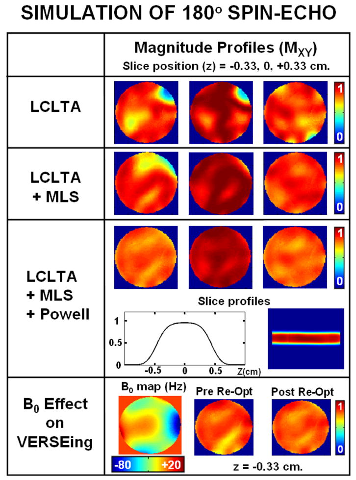
Figure 7 shows simulated excitation profiles of the 180° spin-echo excitation at three z positions (0, ± 0.33 cm) along the excited slice for various design techniques. Clearly, the profiles resulting from the LCLTA design (top row) do not provide adequate excitation homogeneity. The profiles from the initial approximation design (second row), which combines the LCLTA design with the MLS criterion, are an improvement on this but still contain significant excitation error. With the addition of the Powell iterative optimization step to the design (third row), profiles with excellent excitation performance can be achieved. The fourth row of the figure illustrates the effect of B0 inhomogeneity on the excitation profile due to VERSEing of the RF pulses. On the left, is the B0 map which ranges from -80 to +20 Hz. In the center is the excitation profile of the VERSEd RF pulse at z = -0.33 cm, illustrating deterioration in the excitation performance when compared to the pre-VERSE profile at the same z position (left of the third row). With application of the re-optimization step via Powell optimization, the excitation homogeneity is returned to the pre-VERSE level (right of fourth row).
Figure 7.
Rows 1-3 are simulated excitation profiles of the 180° spin-echo at three z-positions (0, ± 0.33 cm.) along the excited slice for various RF design techniques. The fourth row illustrates the effect of B0 inhomogeneity on the excitation profile due to VERSEing. This effect can be mitigated by re-optimization via Powell optimization.
Table 1 provides a quantitative comparison of the performance of the various RF design techniques. In the first column, the excitation performance is compared using the normalized standard deviation value. Comparison of the total RF energy (J) and maximum RF voltage (V) are provided in the second and third column, respectively. From the table it is clear that the excitation performance of the proposed method significantly outperformed that of the standard LCLTA design, providing a reduction in excitation error of ∼60%. In addition, as a result of VERSEing and constraining the maximum RF voltage, both the total RF energy and maximum RF voltage are also significantly lowered. Note that with our proposed design, in the first round of the Powell optimization the maximum RF voltage was limited to be 800 V (∼2/3 of the maximum voltage pre-optimization) to reduce the subsequence increase in pulse duration resulting from VERSEing. Nonetheless, with this constraint, the optimization still converged to a solution that provides good excitation performance.
Table 1.
Comparison of the excitation performance and energy and voltage requirement of the various RF designs.
| Normalized RMMSE | Total Energy (J) | Max RF (V) | |
|---|---|---|---|
| LCLTA | 1 | 37.9 | 1495 |
| LCLTA+MLS | 0.870 | 25.4 | 1223 |
| LCLTA+MLS+Powell | 0.406 | 19.3 | 771 |
| > VERSED | 0.586 | 4.07 | 120 |
| > Re-optimized | 0.411 | 4.06 | 122 |
Discussion and conclusions
In this work, we outlined a design method for slice-selective large-flip-angle parallel RF excitation and provided the first experimental demonstration of slice-selective high-flip-angle B1+ mitigation at 7T using parallel transmission. The method was used to design both 90° and spin-echo slice-selective excitations that mitigate severe B1+ inhomogeneity at a level similar to that observed in human in vivo imaging at 7T. The RF excitations were experimentally tested via an 8-channel parallel transmission system, with experimental results providing validation for both the B1+ inhomogeneity mitigation performance as well as the flip-angle accuracy of the excitations. Slice-selective excitations with parallel RF systems offer means to implement conventional high-flip excitation sequences without severe pulse-duration penalty, even at very high B0 field strengths where large B1+ inhomogeneity is present.
Based on the performance of the RF pulse design computation performed entirely in Matlab on a Linux Intel® Xeon 3 GHz server, the initial approximation design calculation time was in the range of 5-8 seconds and the Bloch iterative optimization calculation time was in the range of 20-30 seconds, resulting in an overall design time of around 1 minute for each RF excitation. (Note that the Bloch iterative optimization has to be performed twice, i.e., both before and after the VERSE step.)
It is clear from Figure 7 and Table 1 that the Powell optimization is crucial for the 180° excitation design. However, the Powell optimization was not critical to the 90° excitation design. For the 90° excitation, the initial approximation design provides excellent excitation that performed well even after the application of VERSE. This is likely due to the fact that the 90° excitation requires a lower flip-angle and consequently the linear class assumption in the LCLTA design is better preserved. Furthermore, the 90° excitation requires relatively low peak RF voltage, and hence the increase in pulse duration due to VERSE is relatively small. With this observation, the 90° excitation can be rapidly created using only the initial approximation design.
Acknowledgments
This work was supported by National Institutes of Health; NIBIB Grant No. R01 EB007942, R01 EB006847, and R01 EB000790; NCRR Grant No. P41RR14075; Siemens Medical Solutions; the Mental Illness and Neuroscience Discovery (MIND) Institute; and R.J. Shillman Career Development Award. Its contents are solely the responsibility authors and do not necessary represent the official views of the NIH.
Footnotes
Please note that the concepts and information presented in this paper are based on research and are not commercially available.
Publisher's Disclaimer: This is a PDF file of an unedited manuscript that has been accepted for publication. As a service to our customers we are providing this early version of the manuscript. The manuscript will undergo copyediting, typesetting, and review of the resulting proof before it is published in its final citable form. Please note that during the production process errors may be discovered which could affect the content, and all legal disclaimers that apply to the journal pertain.
References
- 1.Bomsdorf H, Helzel T, Kunz D, Roschmann P, Tschendel O, Wieland J. Spectroscopy and imaging with a 4 tesla whole-body MR system. NMR Biomed. 1988;1:151–8. doi: 10.1002/nbm.1940010308. [DOI] [PubMed] [Google Scholar]
- 2.Vaughan JT, Garwood M, Collins CM, Liu W, DelaBarre L, Adriany G, Andersen P, Merkle H, Goebel R, Smith MB, Ugurbil K. 7T vs. 4T: RF power, homogeneity, and signal-to-noise comparison in head images. Magn Reson Med. 2001;46:24–30. doi: 10.1002/mrm.1156. [DOI] [PubMed] [Google Scholar]
- 3.Saekho S, Yip CY, Noll DC, Boada FE, Stenger VA. Fast-kz three-dimensional tailored radiofrequency pulse for reduced B1 inhomogeneity. Magn Reson Med. 2006;55:719–24. doi: 10.1002/mrm.20840. [DOI] [PMC free article] [PubMed] [Google Scholar]
- 4.Ulloa JL, Irarrazaval P, Hajnal JV. Exploring 3D RF shimming for slice selective imaging. Proceedings of the 13th Annual Meeting of ISMRM; Miami Beach, Florida, USA. 2005. p. 21. [Google Scholar]
- 5.Sung K, Cunningham CH, Nayak KS. Validation of B1+ Non-uniformity Correction in the Chest at 3T using TIP-COMP. Proceedings of the 14th Annual Meeting of ISMRM; Seattle, Washington, USA. 2006. p. 597. [Google Scholar]
- 6.Ibrahim TS, Lee R, Baertlein BA, Abduljalil AM, Zhu H, Robitaille PM. Effect of RF coil excitation on field inhomogeneity at ultra high fields: a field optimized TEM resonator. Magn Reson Imaging. 2001;19:1339–47. doi: 10.1016/s0730-725x(01)00404-0. [DOI] [PubMed] [Google Scholar]
- 7.Mao W, Smith MB, Collins CM. Exploring the limits of RF shimming for high-field MRI of the human head. Magn Reson Med. 2006;56:918–22. doi: 10.1002/mrm.21013. [DOI] [PMC free article] [PubMed] [Google Scholar]
- 8.Vaughan T, DelaBarre L, Snyder C, Tian J, Akgun C, Shrivastava D, Liu W, Olson C, Adriany G, Strupp J, Andersen P, Gopinath A, van de Moortele PF, Garwood M, Ugurbil K. 9.4T human MRI: preliminary results. Magn Reson Med. 2006;56:1274–82. doi: 10.1002/mrm.21073. [DOI] [PMC free article] [PubMed] [Google Scholar]
- 9.Silver MS, Joseph RI, Hoult DI. Highly selective 90° and 180° pulse generation. J Magn Reson. 1984;59:347–351. [Google Scholar]
- 10.Garwood M, DelaBarre L. The return of the frequency sweep: designing adiabatic pulses for contemporary NMR. J Magn Reson. 2001;153:155–77. doi: 10.1006/jmre.2001.2340. [DOI] [PubMed] [Google Scholar]
- 11.Pauly J, Nishimura D, Macovski A. A k-space analysis of small-tip angle excitation. J Magn Reson. 1989;81:43–56. doi: 10.1016/j.jmr.2011.09.023. [DOI] [PubMed] [Google Scholar]
- 12.Setsompop K, Zelinski AC, Goyal VK, Wald LL, Adalsteinsson E. Sparse spokes slice selective design for B1 inhomogeneity correction at 7T. Proceedings of the 15th Annual Meeting of ISMRM; Berlin, Germany. 2007. p. 356. [Google Scholar]
- 13.Katscher U, Bornert P, Leussler C, van den Brink JS. Transmit SENSE. Magn Reson Med. 2003;49:144–50. doi: 10.1002/mrm.10353. [DOI] [PubMed] [Google Scholar]
- 14.Zhu Y. Parallel excitation with an array of transmit coils. Magn Reson Med. 2004;51:775–84. doi: 10.1002/mrm.20011. [DOI] [PubMed] [Google Scholar]
- 15.Griswold M, Kannengiesser S, Muller M, Jakob P. Autocalibrated accelerated parallel excitation (transmit-GRAPPA). Proceedings of the 13th Annual Meeting of ISMRM; Miami Beach, FL, USA. 2005. p. 2435. [Google Scholar]
- 16.Grissom W, Yip CY, Zhang Z, Stenger VA, Fessler JA, Noll DC. Spatial domain method for the design of RF pulses in multicoil parallel excitation. Magn Reson Med. 2006;56:620–9. doi: 10.1002/mrm.20978. [DOI] [PubMed] [Google Scholar]
- 17.Ullmann P, Junge S, Wick M, Seifert F, Ruhm W, Hennig J. Experimental analysis of parallel excitation using dedicated coil setups and simultaneous RF transmission on multiple channels. Magn Reson Med. 2005;54:994–1001. doi: 10.1002/mrm.20646. [DOI] [PubMed] [Google Scholar]
- 18.Setsompop K, Wald LL, Alagappan V, Gagoski B, Hebrank F, Fontius U, Schmitt F, Adalsteinsson E. Parallel RF transmission with eight channels at 3 Tesla. Magn Reson Med. 2006;56:1163–71. doi: 10.1002/mrm.21042. [DOI] [PubMed] [Google Scholar]
- 19.Zhang Z, Yip CY, Grissom WA, Noll DC, Boada FE, Stenger VA. Reduction of transmitter B1 inhomogeneity with transmit SENSE slice-select pulses. Magn Reson Med. 57:842–7. doi: 10.1002/mrm.21221. [DOI] [PMC free article] [PubMed] [Google Scholar]
- 20.Setsompop K, Wald LL, Alagappan V, Gagoski BA, Adalsteinsson E. Magnitude Least Squares Optimization for Parallel RF Excitation Design Demonstrated at 7 Tesla with 8 Channels. Magn Reson Med. 2008;59:908–915. doi: 10.1002/mrm.21513. [DOI] [PMC free article] [PubMed] [Google Scholar]
- 21.Ulloa JL, Callaghan M, Guarini M, Hajnal JV, Irarrazaval P. Calculation of B1 pulse for RF shimming at arbitrary flip angle using multiple transmitters. Proceedings of the 14th Annual Meeting of ISMRM; Seattle, Washington, USA. 2006. p. 3016. [Google Scholar]
- 22.Grissom WA, Fessler JA, Noll DC. Time-Segmented Spin Domain Method for Fast Large-Tip-Angle RF pulse Design in Parallel Excitation. Proceedings of the 15th Annual Meeting of ISMRM; Berlin, Germany. 2007. p. 676. [Google Scholar]
- 23.Grissom WA, Fessler JA, Noll DC. Additive-Angle Method for Fast Large-Tip-Angle RF Pulse Design in Parallel Excitation. Proceedings of the 15th Annual Meeting of ISMRM; Berlin, Germany. 2007. p. 1689. [DOI] [PubMed] [Google Scholar]
- 24.Setsompop K, Zelinski AC, Alagappan V, Hebrank F, Fontius U, Schmitt F, Wald LL, Adalsteinsson E. High flip angle slice selective Parallel RF Excitation on an 8-channel system at 3T. Proceedings of the 15th Annual Meeting of ISMRM; Berlin, Germany. 2007. p. 677. [Google Scholar]
- 25.Xu D, King KF, Zhu Y, McKinnon G, Liang Z. Multidimensioinal Arbitrary-Flip-Angle Parallel Transmit Pulse Design Using an Optimal Control Approach. Proceedings of the 15th Annual Meeting of ISMRM; Berlin, Germany. 2007. p. 1696. [Google Scholar]
- 26.Xu D, King KF, Zhu Y, McKinnon GC, Liang ZP. A noniterative method to design large-tip-angle multidimensional spatially-selective radio frequency pulses for parallel transmission. Magn Reson Med. 2007;58:326–334. doi: 10.1002/mrm.21314. [DOI] [PubMed] [Google Scholar]
- 27.Pauly J, Nishimura D, Macovski A. A linear class of large-tip-angle selective excitation pulses. J Magn Reson. 1989;82:571–587. [Google Scholar]
- 28.Kerr AB, Zhu Y, Pauly JM. Phase Constraint Relaxation in Parallel Excitation Pulse Design. Proceedings of the 15th Annual Meeting of ISMRM; Berlin, Germany. 2007. p. 1694. [Google Scholar]
- 29.Pauly J, Le Roux P, Nishimura D, Macovski A. Parameter relations for the Shinnar-Le Roux selective excitation pulse design algorithm. IEEE Transactions on Medical Imaging. 1991;10:53–65. doi: 10.1109/42.75611. [DOI] [PubMed] [Google Scholar]
- 30.Xu D, King KF, Zhu Y, McKinnon G, Liang Z. Reducing B1 Inhomogeneity Using Optimized Parallel Transmit Pulses. Proceedings of the 15th Annual Meeting of ISMRM; Berlin, Germany. 2007. p. 1700. [Google Scholar]
- 31.Press WH. Numerical recipe in C. Cambridge University Press; Cambridge: 1992. [Google Scholar]
- 32.Conolly SM, Nishimura DG, Macovski A, Glover GH. Variable-rate selective excitation. J Magn Reson. 1988;78:440–458. [Google Scholar]
- 33.Wu X, Akgun C, Vaughan JT, Ugurbil K, van de Moortele PF. SAR Reduction in Transmit SENSE Using Adapted Excitation k-space Trajectories. Proceedings of the 15th Annual Meeting of ISMRM; Berlin, Germany. 2007. p. 673. [Google Scholar]
- 34.Graesslin I, Biederer S, Schweser F, Zimmermann KH, Katscher U, Börnert P. SAR Reduction for Parallel Transmission using VERSE and k-space Filtering. Proceedings of the 15th Annual Meeting of ISMRM; Berlin, Germany. 2007. p. 674. [Google Scholar]
- 35.Setsompop K, Zelinski AC, Alagappan V, Nistler J, Hebrank F, Fontius U, Schmitt F, Wald LL, Adalsteinsson E. In vivo Parallel RF Excitation with B0 correction. Proceedings of the 15th Annual Meeting of ISMRM; Berlin, Germany. 2007. p. 671. [Google Scholar]
- 36.Alagappan V, Adalsteinsson E, Setsompop K, Fontius U, Zelinski AC, Wiggins GC, Hebrank F, Schmitt F, Wald LL. Comparison of Three Transmit Arrays for Parallel Transmit. Proceedings of the 15th Annual Meeting of ISMRM; Berlin, Germany. 2007. p. 35. [Google Scholar]
- 37.Lin FH, Kwong KK, Belliveau JW, Wald LL. Parallel imaging reconstruction using automatic regularization. Magn Reson Med. 2004;51:559–67. doi: 10.1002/mrm.10718. [DOI] [PubMed] [Google Scholar]
- 38.Setsompop K, Alagappan V, Gagoski B, Witzel T, Polimeni J, Potthast A, Hebrank F, Fontius U, Schmitt F, Wald LL, Adalsteinsson E. Slice-Selective RF pulses for In-vivo B1+ Inhomogeneity Mitigation at 7 Tesla using Parallel RF Excitation with a 16-Element Coil. doi: 10.1002/mrm.21739. Magn Reson Med accepted for publication. [DOI] [PMC free article] [PubMed] [Google Scholar]


