Abstract
A factor that limits the use of multiphoton microscopy (MPM) in clinical and preclinical studies is the lack of a compact and flexible probe. We report on a miniaturized MPM probe employing a microelectromechanical system (MEMS) scanning mirror and a double-clad photonic crystal fiber (DCPCF). The use of a MEMS mirror and a DCPCF provides many advantages, such as size reduction, rapid and precise scanning, efficient delivery of short pulses, and high collection efficiency of fluorescent signals. The completed probe was 1 cm in outer diameter and 14 cm in length. The developed probe was integrated into an MPM system and used to image fluorescent beads, paper, and biological specimens.
Multiphoton microscopy (MPM) employs such nonlinear processes as two-photon excited fluorescence (TPEF) or second-harmonic generation to image structural and functional properties of living tissues [1,2]. TPEF, which occurs only at the focal point of the microscope, minimizes photobleaching and photo-damage during the imaging of live cells. The advantages of MPM also include intrinsic sectioning capability owing to nonlinear interaction and deep tissue imaging by near-infrared light. These combined benefits result in a broad range of applications as a noninvasive diagnostic tool for imaging biological specimens. Most MPM instruments depend on benchtop microscopes, which are not ideal for in vivo clinical applications. Several researchers have explored methods to develop a compact MPM probe for this reason [3-8]. Key criteria for such probes are a compact scanning mechanism, efficient delivery of an ultrashort pulse, collection of fluorescence signal, integration, and packaging.
To satisfy these requirements, we utilized a dual-axis microelectromechanical system (MEMS) scanning mirror and a double-clad photonic crystal fiber (DCPCF) to develop a miniaturized MPM probe. Most scanning methods seen in portable probes are based on the use of a pair of galvanometers or piezoelectric actuators operated at the mechanical resonance frequency. These methods achieve high-speed scanning but are limited by either their size or the control of the scanning speed. In recent years, a scanning method using MEMS mirrors has been used in compact imaging probes [7-10]. The MEMS technology employed in this work has many advantages, including rapid scanning, small size, high reliability, mass production, and flexibility in scanning-pattern capabilities. Thus the use of a MEMS scanning mirror in an MPM probe provides not only a reduction of probe size but also rapid data acquisition for a real-time, in vivo clinical study. To date, a major obstacle in developing an MPM fiber probe is the realization of a waveguide to efficiently deliver the ultrashort pulsed light and collect fluorescence signals from samples. The use of single/multimode fibers has been used as replacement for the conventional bulk and free-space optics of benchtop MPM. However, there is a trade-off between excitation and collection efficiency. Single-mode fibers (SMFs) are better for excitation but have a much lower collection efficiency than multimode fibers [11,12]. In addition, the shape and spectrum of an intense short pulse are degraded while traveling in the SMF core by a nonlinear process known as self-phase modulation (SPM). The recent advent of DCPCF overcomes this limitation [8,12].
The structure of the DCPCF consists of a large core surrounded by both an inner and an outer cladding. The excitation light propagates through the single-mode core, and the collected fluorescence light signal travels through the cladding, which supports multi-modal propagation. The DCPCF not only enhances the sensitivity but also minimizes the SPM, because the relatively large core can significantly reduce the power density of short-pulse light.
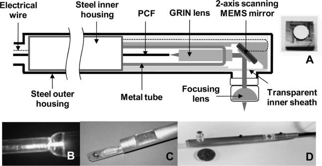
In our study, we merge the benefits of the MEMS scanning mirror and the DCPCF to realize a completed probe. The schematic and photos of the developed MPM probe are presented in Fig. 1. Our probe is comprised of a two-axis scanning MEMS mirror, a DCPCF, a gradient index (GRIN) lens, and an aspheric lens mounted in aluminum housing. The structure and scanning mechanism of the MEMS mirror is very similar to that in our previous work for endoscopic optical-coherence tomography [9,10]. The device employed in this particular study had a 2 mm diameter mirror and exhibited x- and y-axis resonant frequencies of 1.26 kHz and 780 Hz, respectively. The scanning angle of each axis was 14° (optical). Figure 1A presents an image of the diced MEMS mirror.
Fig. 1.
Schematic and photographs of the developed MPM probe. A, Photograph and schematic of two-axis MEMS mirror. The 2 mm mirror was fabricated in a separate process and later bonded to the actuator. B, Photograph of GRIN lens assembled with DCPCF. C, MEMS mirror and pigtailed GRIN lens mounted to custom-made packaging. Photograph depicts the inner portion of the probe prior to integration with the outer housing. D, Photograph of completed probe. Submarine-shaped probe compared for size to a U.S. quarter coin. The distance of the aspheric lens to the MEMS devices is adjustable.
The DCPCF (Crystal Fibre A/S) that was used in this work has a core diameter of 16 μm and an inner cladding with a diameter of 163 μm. A Ti:sapphire laser was first coupled with a 1 m DCPCF and guided to the core. To generate the collimated beam, the DCPCF and a 1.8 mm GRIN lens (0.22 pitch, NA =0.6) were then aligned in the transparent tubing. The optimal collimating beam was monitored by the adjustment of the span between the DCPCF and GRIN lens and glued with UV curing adhesive (Fig. 1B). The assembled pigtailed GRIN lens was inserted into a 2.5 mm diameter metal tube, aligned in the center, and secured again in order to protect from breakage. For integration and packaging, all mounts, the alignment bench, and housings were fabricated. The MEMS scanner was mounted on one end of a 45° platform located on the alignment bench to serve as a support for the mirror die; sufficient material remained on the tube walls to maintain mechanical rigidity and structural integrity. A pigtailed GRIN lens was mounted on the other end of the alignment bench and temporarily held in place while the MEMS mirror was positioned. Coarse alignment of the components was achieved, utilizing a stereoscope and a visible laser coupled into the pigtailed GRIN lens. The mirror was then fixed in place, and wirebond connections were made between the MEMS die and alignment bench. The assembled device was covered by a transparent protective top piece and inserted into the aluminum inner housing; the alignment bench was then secured with epoxy, as depicted in Fig. 1C. The inner housing was then inserted inside a machined outer housing. Finally, a focusing lens (D =5 mm) was placed on the mount and aligned on the center of the beam from the MEMS mirror. For convenience of alignment, railed notch sets were made in both the steel inner and outer housing. The completed probe resembles a submarine, as shown in Fig. 1D. The outer diameter and length were 1 cm and 14 cm, respectively. The diameter of the lens mount was 7 mm, and the length was varied from 6 mm to 1.5 cm.
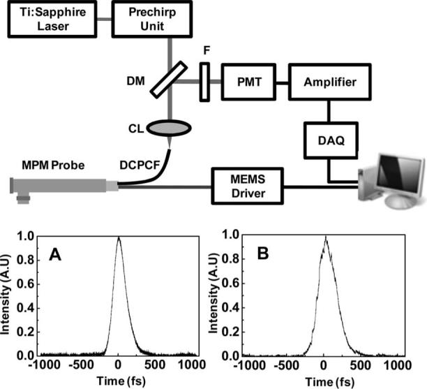
The completed probe was incorporated into the MPM system, as presented in Fig. 2. A Ti:sapphire laser provided the excitation source at a wavelength of 790 nm and a bandwidth of 10 nm. The average laser output power was 450 mW at 76 MHz. The femtosecond pulses from the laser were negatively prechirped by grating pairs in order to compensate for positive dispersion resulting from beam propagation through the core of the DCPCF. To confirm dispersion compensation, the pulse duration was measured before and after propagation through the MPM probe. Figures 2A and 2B provide plots of the pulse width directly from laser and after compensation. The 190 fs pulse (Fig. 2A) from the laser was broadened by more than 2 ps, which was compensated as 260 fs (Fig. 2B). The beam was then launched into the DCPCF using a coupling lens (NA=0.1, 5×) and reflected by a MEMS mirror. An aspheric lens (f=4.03, NA=0.62) was used to focus the scanned beam from the MEMS mirror. The fluorescence signal emitted by the sample was collected back through the cladding of the DCPCF and separated from the input beam with a dichroic mirror. The fluorescence signal was then filtered by the bandpass filter (center wavelength, 550 nm) and directed toward a photomultiplier tube (PMT). The signal from the PMT was amplified, digitized, and visualized as an image.
Fig. 2.

Schematic of MPM incorporated with probe: F, filter; DM, dichroic mirror; CL, coupling lens; DCPCF, double-clad photonic crystal fiber. To compensate the positive dispersion owing to 1 m DCPCF, prechirping units using a grating pair were used. The MEMS mirror was controlled by a sychnonized signal generated by the imaging computer: A, measurement of laser pulse duration (190 fs); B, pulse duration after prechirping units. Broadened pulse (more than 2 ps) was minimized up to 260 fs.
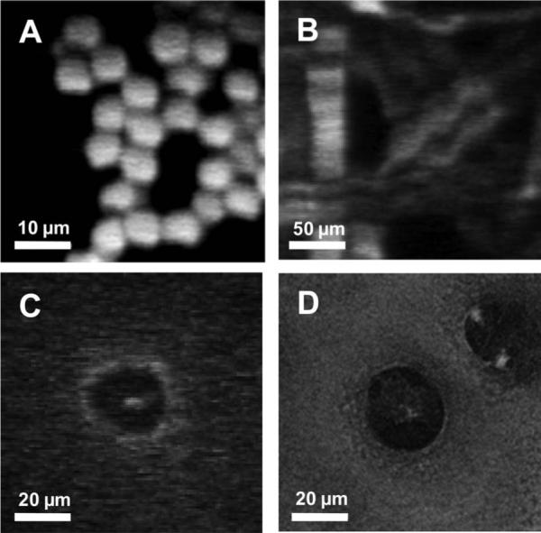
Figure 3A shows an image of 6 μm fluorescence beads. The image consists of 128×128 pixels at a scanning rate of 10 Hz. The excitation power delivered to the sample was 15 mW through the core of the DCPCF. Figure 3B depicts an MPM image of a piece of paper. Fluorescent whitening agents are commonly added to paper during manufacture to impart whiteness and brightness. The paper containing fluorescent whitening agents generates a high fluorescence signal. The acquired image visualizes the grid structure of the paper with detailed fibers. To prove the imaging capability using the developed probe for clinical study, we imaged in vitro articular cartilage of rabbit. Tissue was incubated with fluorescein solution prior to imaging. Articular cartilage contains chondrocytes that vary in number, shape, and orientation at different locations. Figure 3C shows the spherical-shaped chondrocyte around 3 mm distance from the superficial region. The center spot indicates the nucleus of the chondrocyte. The performance of our system was also compared to a commercial MPM system (Zeiss LSM 510 NLO Meta microscope). The imaging parameters of the commercial MPM were matched with the same values as our developed system: optical power at the sample, wavelength, NA of the objective lens, and scanning rate. The cartilage tissue shown in Fig. 3C was imaged again and aimed at the same site of the sample. The obtained image was correlated very well in terms of shape and size of chondrocyte, as presented in Fig. 3D. However, unmatched factors, mainly the pulse widths and sensitivity of the PMT, determined a difference of image quality.
Fig. 3.

In-vitro MPM images using the compact probe. The excitation power at the sample was 15 mW. A, Image of 6 μm fluorescent beads. B, Image of paper. Each fiber is clearly visualized. C, Image of chondrocyte in a articular cartilage. D, Image of chondrocytes by commercial MPM system.
In summary, a portable MPM probe using a MEMS mirror was designed and constructed. A dual-axis MEMS mirror takes the place of conventional scanning mirror and enables the compact probe geometry. The probe also allows efficient delivery of a short-pulse laser and collection of fluorescent signals owing to DCPCF and the large diameter of the MEMS mirror. The probe was integrated into an MPM system and provided high-resolution images comparable with a commercial system. A future version of the current device could function as an endoscopic tool by means of optimal micro optics and further reduction in packaging size. Such a compact probe may greatly expand the applications of MPM and is a promising device for high-resolution diagnostic imaging.
Acknowledgments
Advanced MEMS is gratefully acknowledged for providing the probe and control system. This work was supported by research grants from the National Science Foundation (BES-86924), National Institutes of Health (EB-00293, NCI-91717, RR-01192), and the Air Force Office of Scientific Research (FA9550-04-1-0101). Support from the Beckman Foundation is also acknowledged.
References
- 1.Denk W, Strickler JH, Webb WW. Science. 1990;248:73. doi: 10.1126/science.2321027. [DOI] [PubMed] [Google Scholar]
- 2.Zipfel WR, Williams RM, Webb WW. Nat. Biotechnol. 2003;21:1369. doi: 10.1038/nbt899. [DOI] [PubMed] [Google Scholar]
- 3.Helmchen F, Fee MS, Tank DW, Denk W. Neuron. 2001;31:903. doi: 10.1016/s0896-6273(01)00421-4. [DOI] [PubMed] [Google Scholar]
- 4.Jung JC, Schnitzer MJ. Opt. Lett. 2003;28:902. doi: 10.1364/ol.28.000902. [DOI] [PubMed] [Google Scholar]
- 5.Flusberg BA, Jung JC, Cocker ED, Anderson EP, Schnitzer MJ. Opt. Lett. 2005;30:2272. doi: 10.1364/ol.30.002272. [DOI] [PubMed] [Google Scholar]
- 6.Myaing MT, MacDonald DJ, Li X. Opt. Lett. 2006;31:1076. doi: 10.1364/ol.31.001076. [DOI] [PubMed] [Google Scholar]
- 7.Piyawattanametha W, Barretto RPJ, Ko TH, Flusberg BA, Cocker ED, Ra H, Lee D, Solgaard O, Schnitzer MJ. Opt. Lett. 2006;31:2018. doi: 10.1364/ol.31.002018. [DOI] [PMC free article] [PubMed] [Google Scholar]
- 8.Fu L, Jain A, Cranfield C, Xie H, Gu M. J. Biomed. Opt. 2007;12:040501–1. doi: 10.1117/1.2756102. [DOI] [PubMed] [Google Scholar]
- 9.Jung W, McCormick DT, Zhang J, Wang L, Tien NC, Chen Z. Appl. Phys. Lett. 2006;88:163901. [Google Scholar]
- 10.Jung W, McCormick DT, Ahn Y, Sepehr A, Brenner M, Wong B, Tien NC, Chen Z. Opt. Lett. 2007;32:3239. doi: 10.1364/ol.32.003239. [DOI] [PubMed] [Google Scholar]
- 11.Ye JY, Myaing MT, Norris TB, Thomas T, Baker J., Jr. Opt. Lett. 2002;27:1412. doi: 10.1364/ol.27.001412. [DOI] [PubMed] [Google Scholar]
- 12.Myaing MT, Ye JY, Norris TB, Thomas T, Baker JR, Jr., Wadsworth WJ, Bouwmans G, Knight JC, St P. J. Russell, Opt. Lett. 2003;28:1224. doi: 10.1364/ol.28.001224. [DOI] [PubMed] [Google Scholar]


