Abstract
The Radio Frequency Ablation Segmentation Tool (RFAST) is a software application developed using NIH's Medical Image Processing Analysis and Visualization (MIPAV) API for the specific purpose of assisting physicians in the planning of radio frequency ablation (RFA) procedures. The RFAST application sequentially leads the physician through the steps necessary to register, fuse, segment, visualize and plan the RFA treatment. Three-dimensional volume visualization of the CT dataset with segmented 3D surface models enables the physician to interactively position the ablation probe to simulate burns and to semi-manually simulate sphere packing in an attempt to optimize probe placement.
Index Terms: Ablation, Biomedical image processing, Blood vessels, Image analysis, Image registration, Image segmentation, Liver, Medical decision-making, Rendering (computer graphics)
I. Introduction
Radio frequency ablation (RFA) of non-resectable malignant tissue in a patient's liver, kidneys, and heart is a rapidly expanding research field and treatment tool for clinicians. A needle-shaped probe device is introduced into the patient percutaneously, laparoscopically or during surgery, targeting the tumor location. High-frequency alternating current is applied through the probe's tip, causing the tissue to heat and necrose.
The information contained in acquired image volumes of the target area can assist clinicians in diagnosis, procedure planning, and post-treatment monitoring. To improve the probability of success for a RFA treatment, accurate placement and monitoring of the thermal lesions are necessary. Knowledge of the spatial relationship between the neoplastic tissue, organ vasculature and other important structures within the patient's body is intimately linked to the success of treatment. Accurate probe placement for ablation-packing with the necessary overlap to ensure the neoplastic tissue and a small margin of normal organ tissue are completely necrosed can be a difficult proposition without proper image guidance and visualization.
II. The RFAST process
The Radio Frequency Ablation Segmentation Tool (RFAST) focuses on assisting clinicians with the planning and evaluation of a RFA procedure performed on malignant hepatic tissue.
RFAST provides the user with the tools necessary to isolate the treatment region within the patient's abdomen and register one data set against a second image volume. RFAST guides the user through the segmentation of the liver, vasculature, and any regions of malignant tissue. These segmentations are then extracted as surface meshes and visualized in our three-dimensional volume renderer, allowing the user to interactively position the RFA probe and determine an optimal series of needle placements to completely ablate the patient's tumor.
NIH's Medical Image Processing Analysis and Visualization (MIPAV) provides RFAST with a full-featured and mature code base to build upon [1]. MIPAV is already a mature medical imaging project with tools for image processing, segmentation, registration, fusion and visualization. RFAST reorganizes these tools in a new interface optimized for the specific needs of the RFA planning and evaluation processes. Where functionality was needed that the MIPAV source code did not provide, new generic algorithms (e.g. the Coherence Enhancing Diffusion Filter) and RFA-specific tools (e.g. the ablation simulation, planning and evaluation facilities) were implemented.
III. Pre-processing
Before RFAST begins its process of segmentation, visualization and planning, it first provides the user with the opportunity to resample, register and fuse image volumes.
A. Image retrieval
To facilitate the exchange and processing of CT, PET, MRI and ultrasound images needed in the RFA treatment process, RFAST has adopted the Digital Imaging and Communications in Medicine (DICOM) image and transfer standard. DICOM is now a mature, evolving, and widely accepted standard that supports communication of medical image information and promotes a common framework enabling networked based picture archiving and communication systems (PACS). Again, RFAST capitalizes on MIPAV significant support of the DICOM 3.0 specification to enable RFAST to query, retrieve, read, process, and write DICOM formatted images.
B. Volume reslicing and resampling
Since many image acquisitions contain more data than is necessary for the RFA planning procedure, RFAST provides tools for the removal of image slices which are judged irrelevant (i.e. those which do not contain the liver and other important structures).
The volume rendering method used in RFAST takes advantage of the rendering capabilities common in today's graphics cards to provide real-time interactive 3D texture-mapped volume rendering. Therefore, any volume the user needs to load into the RFAST volume renderer must be resampled so that each dimension is a power of two and the resampled datasets are used in subsequent processing and visualization steps. If a volume is judged to be too large to fit within the user's graphics card memory or decreased processing time is desired, the in-plane dimensions of the volume can be downsampled by a factor of two. Additionally, if more in-depth processing of the image volume is required, all of the algorithms and image processing utilities implemented within MIPAV are readily available to the user.
C. Registration and fusion
RFAST provides a number of registration methods to assist in the planning and evaluation of the RFA treatment process. The registration methods are generally broken into two broad categories: user-guided and automatic. The user-guided methods require the user (a trained expert) to identify homologous landmarks in the source image and the target image. This process can be slow and requires the user to precisely identify the landmarks, however, once the landmarks are selected the image registration process is quite fast. Two major landmark based methods are available in RFAST: rigid [2], and thin-plate splines [3]. The rigid method allows for six degrees of freedom (for the registration of 3D datasets), three degrees of rotation and three degrees of translation. The thin-plate splines method is inherently non-linear and can result in better registration of images of the abdomen where there may be non-linear changes do to breathing artifacts and organ movement. The second class of registration algorithms are the automatic methods which rely on voxel similarity measures to guide the registration. Voxel similarity methods include normalized mutual information [4], [5], cross-correlation [6], and least squares, and provide a metric that guides the registration to an acceptable solution. The range of voxel similarity measures gives the user the ability to choose the best measure for the specific registration task. For example, the normalized mutual information works well when performing a inter-modality registration task. The user can choose between multiresolution affine or non-linear B-spline methods, depending on the specific requirements. The affine method [7] provides up to twelve degrees of freedom (three rotation, three translation, three zoom and three skew) where registration time (performed on 3.0GHz Pentium 4 processor) is approximately eight to ten minutes. The non-linear method provides a more general solution but processing times can be as long as two to three hours.
Through fusing multi-modality image volumes (i.e., CT and PET) clinicians can better visualize the spatial relationship between the tumor and the important morphological features within the patient's body during treatment planning. Comparison of inter-operatively acquired morphological image volumes to pre-operative functional volumes allows clinicians to evaluate the progress of the RFA process and whether more ablations might be needed to fully necrose the treatment area. Fusion of pre and post operative image volumes is also quite useful in evaluating the effectiveness of the RFA procedure and early detection of tumor regrowth.
IV. Segmentation
A. Liver
To address the complexity of the shape of human organs and the difficulty in the discrimination of all their boundaries from boundaries of adjacent structures in CT volumes, a combination of semi-automatic and automatic algorithms is used to define volume of interest contours (VOIs) in the 3D dataset.
The livewire paradigm is one method that has proven effective and efficient in the semi-automatic segmentation of many structures of interest [8]. An initial VOI of the resampled volume is drawn to define the boundary of the liver in an image plane that bisects the liver using a livewire tool. The livewire tool minimizes a cost function composed of the image's gradient magnitude, gradient direction, and Laplacian zero crossings between the user's last click within the image slice and the current position of the mouse, allowing the user to interactively visualize and select the optimal segmentation quickly, but with decreased user-derived variability compared to a fully manual segmentation [9].
Once the structure is segmented in one slice, the user can propagate this contour to the adjacent slices in both directions using a combination of an optimization to translate, rotate and scale the VOI to the new slice, and the application of a boundary evolution algorithm [10] to the points of the VOI, to conform to the boundary of the structure in the new slice. Next, RFAST checks the image intensities along the new VOI contour and rejects the new boundary if the intensities have changed significantly when compared to the previous slice. When this occurs the user can restart the process by performing the livewire segmentation on this new slice and attempting to propagate it up or down in the volume's unsegmented slices. Once this semi-automatic segmentation process is completed, the user can quickly correct the VOI segmentation using a number of manual methods which RFAST shares with MIPAV, including levelset VOIs and manual boundary adjustment. After the liver is fully segmented, a surface mesh can be extracted and is included for visualization and planning.
B. Tumors and ablations
The VOI segmentation process can be repeated to create surfaces of other structures, including any tumor in the case of a pre-treatment image, or the ablated areas in a post-treatment volume.
An accurate segmentation of any malignant tissue within the liver is critical for accurate treatment visualization, planning and evaluation. The spatial relationship between a tumor, the two hepatic vasculature trees and other structures within the patient's torso can impact the tumor's treatment. For example, vasculature close to a tumor acts as a heat-sink as the tissue is ablated, reducing the amount and shape of necrosed tissue.
Additionally, complete ablation of all malignant tissue is essential to minimize the probability of tumor regrowth. To this end, knowledge of the tumor location and size is important when simulating ablations, since the user must devise a treatment plan which adequately covers the malignant area. In addition to ablating the diseased tissue, it is also recommended by the RFA probe manufacturers that a small margin of approximately one centimeter surrounding the tumor be ablated as well, to further decrease the possibility of tumor regrowth. Registration and fusion of a PET acquisition to a pre-treatment CT volume can also be useful in finding areas which may contain malignant tissue, but which do not appear abnormal in the CT scan.
Segmentation of ablated regions within post-treatment image volumes can also assist clinicians, allowing them to compare the treated region to the pre-treatment tumor segmentation, which is transformed into the post-treatment image volume when the two datasets are registered. This comparison gives clinicians information on the effectiveness of the RFA treatment and can alert them to situations were re-treatment may be necessary.
C. Vasculature
Segmentation of the hepatic vasculature is important to the visualization of the RFA procedure. Vasculature in close proximity to the treatment region needs to be taken into account by the clinician. These vessels act as heat-sinks, significantly altering the region of necrosed tissue depending on the location and size of the vessel. Knowledge of the hepatic vasculature's geometric information and spatial position is key to any effort to accurately model the thermal field of an ablation. Research into the computation of these temperature profiles and the corresponding regions of necrosed tissue through the use of Finite Element modeling [11]–[13] require these data. A properly segmented vasculature allows RFAST to alert the user to unfeasible treatment paths which intersect a vessel, possibly endangering the health of the patient.
All this is not to say that a perfect, manual segmentation is necessarily required. The effect a vessel has on a given ablation is a function of its proximity to the ablation and the amount of blood flowing through it. Therefore, very small vessels and those which are a great distance away from the area of malignant tissue do not require as precise a segmentation. To this end, RFAST employs an interactive method for segmentation of the vasculature. This method provides an acceptable segmentation of both the venous and arterial vasculature trees and allows for manual evaluation and refinement of the vessels most likely to have an effect on the procedure.
To begin the RFAST vasculature segmentation process, the liver must first be isolated from the remainder of the image volume using the liver segmentation created previously. To generate a maximum intensity projection (MIP) which is optimized for segmentation of the liver's vasculature tree, the liver volume is processed with both median and coherence enhancing diffusion [14], [15] filters. These filters serve to make the image volume intensities more consistent locally, allowing for an easier and more accurate segmentation of the vasculature from the remainder of the liver. The coherence enhancing diffusion filter in particular works well in this regard when its parameters are selected carefully, blurring the image only in areas which it finds to have high “vessel-ness” measures.
A MIP rendering is generated of the filtered liver volume to provide the user with a better view of the liver's internal, contrast-enhanced vasculature trees. RFAST searches for points within the MIP which are part of the vasculature based on Hounsfield values. These points are displayed to the user directly on the MIP, allowing the user to rapidly select where three-dimensional region growing within the liver's vasculature tissue should begin. The user can also click on arbitrary points within the MIP to designate them as seed points for three-dimensional region grows, also performed within the original volume. These regions are shown as “painted” and can be refined manually by the user to ensure they contain all of the vasculature. This painted region is then converted to a mask image and holes are reduced using a morphological closing operation. Finally, a surface mesh of the vascular tree is extracted from the image mask.
V. Visualization and planning
Once all the necessary surfaces are extracted, the user can visualize the RFA procedure using a multi-planar orthogonal slice view of the image volume and a three-dimensional volume rendering. The extracted mesh surfaces are added into these renderings along with one of many models representing different RFA probe needles.
A. Probe and ablation modeling
The physical characteristics of the probe, along with its appearance in the visualization are customizable to match the attributes of the wide variety of probe models that are used in ablations. The shape of the ablations generated by each probe can also be altered to match the ablation generated by the real probe.
Currently, RFAST contains several fictional RFA probes with geometries and ablation models which are intended to demonstrate the variety which its simulation framework can accommodate. Another probe model, based on probes sold under the name CoolTip by Radionics, Inc., has also been incorporated into RFAST.
This brand of RFA needle has a straight probe tip and produces ablation volumes which are approximately ellipsoidal. The size of the necrosed volume of tissue depends on the length of the exposed heating element tip, which can vary from two centimeters to seven centimeters. By ignoring the effect of the vasculature and other inhomogeneities within the liver, RFAST is able to simply approximate the CoolTip probe ablations by generating an ellipsoid-shaped surface mesh, scaled according to published experimental data [16].
More probe models from different manufacturers can easily be added through creating a visual model for the probe needle using the Java3D API and providing a method to generate an ablation surface mesh of the proper size and geometry.
B. Treatment simulation
The probe can be moved in relation to the image volume in many ways: it can be rotated about a target point (the center of the volume or the center of mass of a tumor surface), shifted in any dimension (thereby changing the target point), and moved toward or away from the target point. The user can also choose another, arbitrary target point for the probe using a tri-planar view of the image volume, which is integrated into the RFAST volume renderer.
If these probe movements result in the probe's path intersecting bone or vasculature tissue, the user is visually alerted and shown where the problematic intersection occurs. A similar indicator is shown where the probe path enters the patient's body, allowing the user to better determine the viability of a treatment path.
The same entry point can be utilized for multiple ablations – RFAST allows for the probe to be rotated and otherwise moved about its current abdominal entry point instead of the target point to more closely simulate the treatment practices of physicians. Clinicians often attempt to use a single entry point in the treatment of a patient to eliminate unnecessary complexity and minimize trauma sustained by the patient during the procedure.
RFAST can also display two orthogonal planes taken from the image volume along the path of the probe and one plane normal to the orientation of the probe needle as it is maneuvered around the volume. These planes allow the user to easily visualize the tissue which the probe will be traversing and the planes parallel to the probe's orientation can be rotated 360 degrees to show all of the nearby tissue.
C. Treatment plan evaluation
Visual analysis of the effectiveness and efficiency of a given treatment plan is important and is the first order of feedback RFAST provides its user. Portions of the target volume which are not adequately ablated are often readily apparent within RFAST's volume rendering. Unfortunately, visualization is not sufficient to detect all the possible problems with a given treatment plan on its own. A series of ablations may leave a region in the interior of the tumor untreated, while the visualization of the ablation surfaces may prevent the user from detecting the problem and taking corrective action. Quantitative and automated methods are also necessary to alert the user when a treatment plan is incomplete or impractical.
To lay the groundwork for quantitative measurements of a treatment plan, RFAST allows the user to simulate treatment of each tumor surface mesh separately. The system first creates a list of tumor surfaces and surfaces representing those tumors with expanded treatment margins. The volume of each surface is calculated, along with a three dimensional binary mask volume indicating voxels which lie within the surface's boundary. As the user positions the RFA needle and places simulated ablations within the image volume rendering, binary mask volumes are similarly generated for each ablation. These binary masks allow RFAST to calculate the volume of an ablation of arbitrary geometry.
Each ablation surface is associated with the tumor surface which it is treating. The combination of this linkage and the previously generated binary masks of the target and ablation surfaces allows RFAST to compare the desired area of treatment with the actual area of treatment for a given RFA plan. The binary masks of all of a target surface's ablations can be combined through an OR operation and the volume of this new mask can be compared to the volume of the tumor surface. If this union of the ablation masks has a volume which is less than the tumor surface volume, that is an indication that not all of the tumor is within the necrosed region and more treatment is necessary.
Since both the surfaces for the segmented tumor and the tumor with an added safety margin are present in the volume renderer, the physician has available both visual and quantitative tools to determine whether a treatment plan adequately necroses the tumor and the safety margin around it. In situations where ablation of the entirety of the tumor and surrounding tissue is not practical, whether for practical or medical reasons, the physician can ensure that a maximal amount of marginal tissue is necrosed. These same quantification methods can also be applied to assist the physician in minimizing the amount of non-diseased tissue outside the safety margin that is necrosed. Reducing the amount of normal hepatic tissue that is ablated is important in ensuring proper liver function after the procedure.
Similarly, the binary mask generated from the tumor surface and mask of the combined ablation surfaces can be directly compared to detect specific areas of malignant tissue which need further treatment. RFAST displays the areas of the tumor which have not been adequately treated as an image volume, allowing the user to easily visualize those areas which need more attention.
VI. Future work
Now that RFAST provides clinicians with tools for pre-processing, segmentation, visualization and planning for RFA procedures, there are a number of features which extend its planning and evaluation capabilities.
First of all, a simple extension to RFAST would be the addition of a greater variety of RFA probe needle models and their accompanying ablation surface mesh calculation routines. This would allow for more clinicians to use RFAST to treat a greater diversity of tumors. Experimental data collection of the ablations created by each RFA probe would be required, whether that data is already published or needs to be gathered first-hand.
RFAST already contains the foundation for the addition of a Finite Element modeling (FEM) system of the RFA procedure's tissue necrosis. FEM of the ablations requires knowledge of the vasculature geometry, due to the vessels' behavior as heat-sinks; tumor location and geometry, because of the different conductivity of malignant tissue; and the ability to simulate ablations of arbitrary geometry. To include a third-party modeling system of the region of necrosed tissue generated by an specific RFA probe needle, one would simply need to create a function, written in Java, which takes as inputs the data required for the simulation, data already gathered by RFAST, and returns a surface mesh representing the calculated volume of tissue which would likely be necrosed during the procedure. Adding this next level of sophistication to the simulation of a RFA procedure would allow clinicians to better plan the treatment of tumors which are located nearby large vessels, which may greatly affect the resulting regions of necrosed tissue.
The addition of a method for automatically packing ablations to treat each tumor would also be very useful. When devising a treatment plan for a tumor, minimizing the amount of healthy tissue necrosed while fully ablating all of the malignant tissue and the one centimeter safety margin around the tumor. There is much research in the literature on the optimized, automatic treatment planning of gamma knife radiosurgery procedures [17], [18]. Other research has been done on the automated placement of RFA ablations, modeled as spheres, within a spherical tumor volume, with the goal of minimizing the possibility of under-ablation and the resulting tumor regrowth by fully necrosing the treatment area [19], [20]. Unfortunately, neither of these approaches fully address all of the issues associated with automated ablation packing in RFA procedures.
Gamma knife radiosurgery planning methods are not directly applicable due to the fact that the path of the RFA probe to a given treatment is critically important, as, unlike radiation, the probe needle is severely restricted in its available paths. RFA probes cannot traverse bone, nor can they enter the patient's body at an angle which would go through the table the patient was placed on. Additionally, the probe should avoid traveling through organs other than the liver within the abdomen, or traversing through large vessels in the hepatic vasculature, as doing so would reduce efficacy of the treatment.
Existing methods for RFA sphere-packing are also not useful when applied to real-world procedure planning. This is chiefly due to their simplifying assumptions about the ablation geometries. The variety of RFA probe ablation shapes is great and ranges from the ellipsoid-shaped ones approximated in RFAST, to “mushroom”-shaped ablations generated by probes from other manufacturers. Secondly, these RFA sphere-packing methodologies fail to take into account the limits on probe path selection and the desirability of entry point reuse.
A RFA-specific ablation-packing scheme within RFAST would likely require input from the user to limit the search range of the optimization. After the user chooses an entry point into the patient's body which targets a specific tumor, RFAST would find a set of ablations which would fully necrose the malignant tissue and its safety margin, while avoiding unpractical probe placements. The positioning of ablations would be limited to within a few degrees of rotation around the entry point from the user's initial choice of probe placement, and to movement toward and away from the probe's target point along its path. The facilities to detect whether a given probe needle position will intersect bone or vasculature tissue are already implemented within RFAST, allowing for evaluation of the automated ablation placement. Additionally, the ability of RFAST to generate mask volumes from arbitrary ablation surface meshes should be helpful in the creation of an algorithm to pack ablations without regard to their geometries within a tumor and its surrounding safety margin. The specifics of such an algorithm, however, have yet to be determined.
Intra-operative interaction with hardware during the procedure also reveals many research possibilities, such as live probe needle tracking and display within RFAST's volume renderer, and robotic needle placement using treatment plans generated from within RFAST. The ability to translate from the coordinates of magnetic or optical position tracking devices attached to the RFA probe needle would allow for intraoperative procedure progress monitoring and evaluation from within RFAST. The clinician's progress could be compared against the pre-determined treatment plan, giving a warning when significant deviation has occurred from the plan. This would, however, require the current position of the RFA probe tracking device to be registered to the pre-operative CT acquisition, whether the scan was taken days or minutes before the procedure.
After translation between the pre-operative image volume and the magnetic or optical position tracking equipment is achieved, extension to the automated guidance of a robotic arm to perform the RFA procedure is also a possible area of research. There are, unfortunately, further significant obstacles which must be addressed before the transition from virtual planning to practical treatment automation is implementable. Steps must be taken to minimize the shifting of the patient's internal organs, especially the liver, as the procedure is performed. Additionally, adjustments need to be made to account for the movement of structures within the patient's abdomen due to respiration.
Another opportunity to incorporate intraoperative data into RFAST is the ultrasound images which some clinicians use to evaluate the progress of a procedure. The ultrasound video feed could be quickly registered to the pre-operative CT acquisition in real-time using position-tracking data obtained from a tracking device attached to the ultrasound equipment. After registration, the ultrasound data could then be displayed in RFAST's texture-mapped three-dimensional volume renderer, giving the clinician real-time information on the spatial position of the probe in relation to the tumor and other structures within the patient's abdomen.
VII. Conclusion
Through optimizing the pre-processing, segmentation, visualization tools available in MIPAV and expanding upon them when necessary, RFAST provides clinicians with the tools necessary to fully exploit the imaging technology currently available. This can result in better pre-treatment planning through volume rendering of the image volume, surface meshes of significant structures within the images, and models of the probe needles used in RFA procedures and their generated thermal lesions. Doctors can easily examine the three-dimensional spatial relationship of these elements, allowing for more accurate needle placement and more effective treatment. Providing facilities for users to register and fuse multi-modality volumes gives them more information about the location of neoplastic tissue in relation to morphological features. Non-linear registration of pre and post treatment volumes could provide for early detection of tumor regrowth. By focusing on the needs of clinicians performing RFA treatments, RFAST is able to provide an optimized user interface for procedure planning, monitoring and evaluation.
Fig. 1.
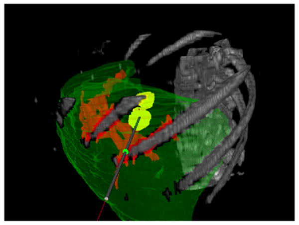
Texture volume renderer visualization with the opacity set to show the patient's ribcage and vertebrae.
Fig. 2.
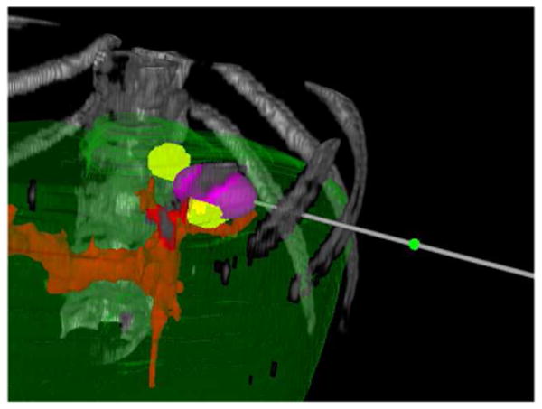
A single simulated ablation shown in the texture volume renderer.
Fig. 3.
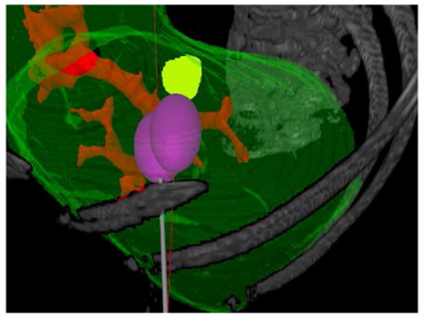
Two simulated ablations using a single entry point shown in the texture volume renderer.
Fig. 4.
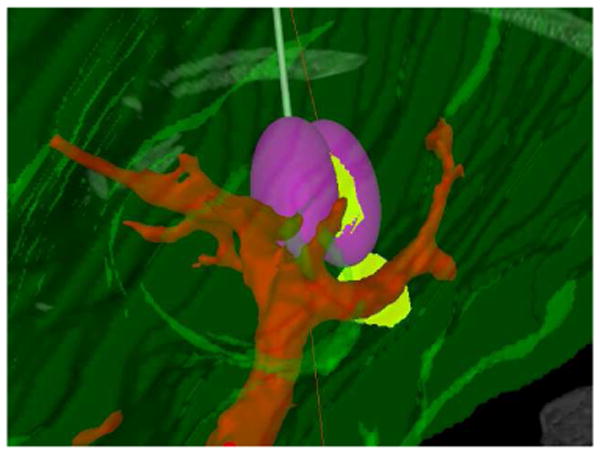
Two simulated ablations using a single entry point shown in the texture volume renderer.
Fig. 5.
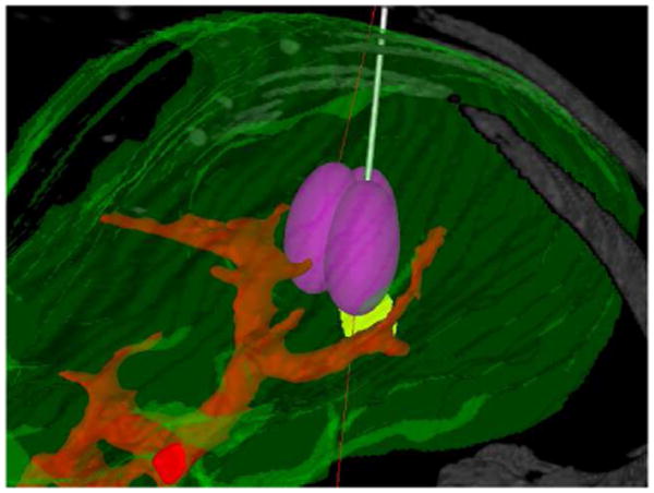
Three simulated ablations using a single entry point shown in the texture volume renderer.
Acknowledgments
This research was supported in part by the Intramural Research Program of the NIH Clinical Center.
Biographies
Evan S. McCreedy Evan obtained his bachelors degree in Computer Science from the College of William and Mary in 2004. He joined the Division of Computational Bioscience at NIH as an intern in the summer of 2002 and now works on development of MIPAV and related medical image processing projects, such as RFAST. His current research interests include parallel processing, image processing, and software engineering.
Ruida Cheng Ruida Cheng received his Computer Science degree from the University of Arizona and is presently working on his master degree in computer science at Johns Hopkins University. He has working on the development of MIPAV and related image processing and visualization projects since joining NIH in 2003. His current research interests include medical image visualization and image processing.

Paul F. Hemler Paul F. Hemler is currently an Associate Professor of Mathematics and Computer Science at Hampden-Sydney College. He have been involved in medical image analysis, processing, and visualization for the past 15 years. He has been a staff member at MIT's Lincoln Laboratory in Lexington MA, a senior research scientist at Stanford University School of Medicine, and an assistant professor in the department of Medical Engineering at Wake Forest University School of Medicine.

Anand Viswanathan Anand obtained his Biomedical Engineering degree and Masters of Science in Engineering from Johns Hopkins University. In July 2005, He became an IRTA Research Fellow for the Diagnostic Radiology Department at NIH. His current research interests include ultrasound, electromagnetic tracking, medical imaging, and medical robotics.
Bradford J. Wood Bradford J. Wood, MD is a diagnostic and interventional radiologist with a CAQ in vascular and interventional radiology. He trained at UVA, Georgetown, and Harvard and is presently a senior clinical investigator and Director of Interventional Radiology Research in the Diagnostic Radiology Department at NIH, with an adjunct appointment in the surgery branch of the National Cancer Institute. Areas of research include: tumor ablation, heat activated drug delivery, medical robotics, device navigation and multimodality procedural visualization.
Matthew J. McAuliffe Dr. Matthew McAuliffe received his Electrical Engineering degree from the University of Detroit and PhD in Biomedical Engineering from the University of North Carolina, Chapel Hill, NC. He has been at NIH since 1998 and is currently the Chief of the Biomedical Image Research and Services Section. He is the original author the MIPAV application and actively manages the continued development of the application. His current research interests include image processing, quantification, and image fusion.
References
- 1.McAuliffe MJ, Lalonde FM, McGarry D, Gandler W, Csaky K, Trus BL. Medical image processing, analysis & visualization in clinical research. CBMS '01: Proceedings of the Fourteenth IEEE Symposium on Computer-Based Medical Systems; IEEE Computer Society; 2001. p. 381. [Google Scholar]
- 2.Arun KS, Huang TS, Blostein SD. Least-squares of two 3d point sets. IEEE Trans Pattern Anal Mach Intell. 1987;9(no 5):698–700. doi: 10.1109/tpami.1987.4767965. [DOI] [PubMed] [Google Scholar]
- 3.Bookstein FL. Principal warps: thin plate splines and the decomposition of deformations. IEEE Trans Pattern Anal Mach Intell. 1989;11(no 6):567–585. [Google Scholar]
- 4.Shannon CE. The mathematical theory of communication (parts 1 and 2) Bell System Technical Journal. 1948;27:379–423. 623–656. [Google Scholar]
- 5.Hill DL, Studholme C, Hawkes DJ. Voxel similarity measures for automated image registration. In: Robb RA, editor. Proc. SPIE Vol. 2359, p. 205-216, Visualization in Biomedical Computing 1994; Sept, 1994. pp. 205–216. [Google Scholar]
- 6.Jenkinson M, Smith S. A global optimisation method for robust affine registration of brain images. Medical Image Analysis. 2001 June;5(no 2):143–156. doi: 10.1016/s1361-8415(01)00036-6. [DOI] [PubMed] [Google Scholar]
- 7.Studholme C, Hill DLG, Hawkes DJ. Automated three-dimensional registration of magnetic resonance and positron emission tomography brain images by multiresolution optimization of voxel similarity measures. Med Phys. 1997 Jan;24(no 1):25–35. doi: 10.1118/1.598130. [DOI] [PubMed] [Google Scholar]
- 8.Mortensen EN, Barrett WA. Interactive segmentation with intelligent scissors. Graphical Models and Image Processing. 1998 September;60(no 5):349–384. [Google Scholar]
- 9.Barrett WA, Mortensen EN. Interactive live-wire boundary extraction. Medical Image Analysis. 19967;1(no 4):331–341. doi: 10.1016/s1361-8415(97)85005-0. [DOI] [PubMed] [Google Scholar]
- 10.Kass M, Witkin A, Terzopoulus D. Snakes: Active contour models. International Journal of Computer Vision. 1987;1:321–331. [Google Scholar]
- 11.Consiglieri L, dos Santos I, Haemmerich D. Tehoretical analysis of the heat convection of coefficient in large vessels and the significance of thermal ablative therapies. Physics in Medicine and Biology. 2003;48:4125–4134. doi: 10.1088/0031-9155/48/24/010. [DOI] [PubMed] [Google Scholar]
- 12.Vorp DA, Steinman DA, Ethier CR. Computational modeling of arterial biomechanics. Computing in Science & Engineering. 2001 Sept/Oct;3(no 5):51–64. [Google Scholar]
- 13.Chang IA, Nguyen UD. Thermal modeling of lesion growth with radiofrequency ablation devices. BioMedical Engineering OnLine. 2004 August;3(no 27) doi: 10.1186/1475-925X-3-27. [DOI] [PMC free article] [PubMed] [Google Scholar]
- 14.Weickert J. Handbook of Computer Vision and Applications. Vol. 2. Apr, 1999. Nonlinear diffusion filtering; pp. 423–450. [Google Scholar]
- 15.Weickert J. Anisotropic Diffusion in Image Processing. Stuttgart, Germany: Teubner; 1998. [Google Scholar]
- 16.Lobik L, Leveillee RJ, Hoey MF. Geometry and temperature distribution during radiofrequency tissue ablation: an experimental ex vivo model. Journal of Endourology. 2005 March;19(no 2):242–247. doi: 10.1089/end.2005.19.242. [DOI] [PubMed] [Google Scholar]
- 17.Shepard DM, Chin LS, DiBiase SJ, Naqvi SA, Lim J, Ferris MC. Clinical implementation of an automated planning system for gamma knife radiosurgery. Int J Radiat Oncol Biol Phys. 2003 Aug;56(no 5):1488–1494. doi: 10.1016/s0360-3016(03)00440-1. [DOI] [PubMed] [Google Scholar]
- 18.Wu Q, Chankong V, Jitprapaikulsam S, Wessels BW, Einstein DB, Mathayomchan B, Kinsella TJ. Real-tim inverse planning for gamma knife radiosurgery. Medical Physics. 2003 Nov;30(no 11):2988–2995. doi: 10.1118/1.1621463. [DOI] [PubMed] [Google Scholar]
- 19.Dodd GD, III, Frank MS, Aribandi M, Chopra S, Chintapalli KN. Radiofrequency thermal ablation: computer analysis of the size of the thermal injury created by overlapping ablations. American Journal of Roentgenology. 2001 October;177:777–782. doi: 10.2214/ajr.177.4.1770777. [DOI] [PubMed] [Google Scholar]
- 20.Khajanchee YS, Streeter D, Swanstrom LL, Hansen PD. A mathematical model for preoperative planning of radiofrequency ablation of hepatic tumors. Surgical Endoscopy. 2004;18:696–701. doi: 10.1007/s00464-003-8180-3. [DOI] [PubMed] [Google Scholar]


