Abstract
The effects of different parameters on the mechanical behaviour of the lumbar spine were in most cases determined deterministically with only one uncertain parameter varied at a time while the others were kept fixed. Thus most parameter combinations were disregarded. The aim of the study was to determine in a probabilistic finite element study how intervertebral rotation, intradiscal pressure, and contact force in the facet joints are affected by the input parameters implant position, implant ball radius, presence of scar tissue, and gap size in the facet joints. An osseoligamentous finite element model of the lumbar spine ranging from L3 vertebra to L5/S1 intervertebral disc was used. An artificial disc with a fixed center of rotation was inserted at level L4/L5. The model was loaded with pure moments of 7.5 Nm to simulate flexion, extension, lateral bending, and axial torsion. In a probabilistic study the implant position in anterior–posterior (ap) and in lateral direction, the radius of the implant ball, and the gap size of the facet joint were varied. After implanting an artificial disc, scar tissue may develop, replacing the anterior longitudinal ligament. Thus presence and absence of scar tissue were also simulated. For each loading case studied, intervertebral rotations, intradiscal pressures and contact forces in the facet joints were calculated for 1,000 randomized input parameter combinations in order to determine the probable range of these output parameters. Intervertebral rotation at implant level varies strongly for different combinations of the input parameters. It is mainly affected by gap size, ap-position and implant ball radius for flexion, by scar tissue and implant ball radius for extension and lateral bending, and by gap size and implant ball radius for axial torsion. For extension, intervertebral rotation at implant level varied between 1.4° and 7.5°. Intradiscal pressure in the adjacent discs is only slightly affected by all input parameters. Contact forces in the facet joints at implant level vary strongly for the different combinations of the input parameters. For flexion, forces are 0 in 63% of the cases, but for small gap sizes and large implant ball radii they reach values of up to 533 N. Similar results are found for extension with a maximum predicted force of 560 N. Here the forces are mainly influenced by gap size, implant ball radius and scar tissue. The forces vary between 0 and 300 N for lateral bending and between 0 and 200 N for axial torsion. The parameters that have the greatest effect in both loading cases are the same as those for extension. Intervertebral rotation and contact force in the facet joints depend strongly on the input parameters studied. The probabilistic study shows a large variation of the results and likelihood of certain values. Clinical studies will be required to show whether or not there is a strong correlation of parameter combinations that cause high facet joint forces and low back pain after total disc replacement.
Keywords: Artificial disc, Finite element analysis, Probabilistic study, Lumbar spine
Introduction
Degenerative disc disease is an indication of total disc replacement. Several types of artificial discs are on the market. Most of them have metallic endplates, which are fixed to the adjacent vertebral bodies. Usually the endplates are linked by a ball-and-socket-joint allowing rotation within the artificial disc. Often a polyethylene inlay takes over the ball part. The inlay is fixed to the caudal endplate (Prodisc-L™, Synthes; Paoli, Pennsylvania), movable in anterior/posterior direction (Activ-L™, B.Braun Aesculap; Tuttlingen, Germany) or movable in a plane parallel to the endplate (Mobidisc™, LDR Médical; Troyes, France). In some disc types, a metallic ball is fixed to the caudal endplate (Maverick™, Medtronik Sofamor Danek; Minneapolis, Minnesota; Flexicore™, Stryker Corp.; Kalamazoo, MI, USA). The Charité™ artificial disc (DePuy Spine; Raynham, MA, USA) has a lentoid sliding core of polyethylene, encased between the biconcave metallic endplates. Devices with a fixed center of rotation are semi-constrained and do not allow pure translation, except when the alignment within the surrounding joint is not respected and lift-off occurs. Clinical success rates amount to about 80% and apply similarly to all disc types mentioned [3, 9–11]. The reasons for the unsatisfying results are not exactly known.
The effect of an artificial disc on the mechanical behavior of the lumbar spine has been studied by several groups using the finite element method [4, 6, 7, 12, 19, 20, 26]. Mostly deterministic models were used by varying one parameter at a time, such as position of the implant, while the others were kept fixed. Combinations, e.g., of extreme values of different parameters were not covered by these studies. However, these combinations may lead to unfavorable intervertebral motions and high facet joint loads and thus to low back pain.
In probabilistic studies, uncertainties and natural variations are incorporated into the model [8]. The values of each input parameter are sampled randomly from the appropriate distribution and used in the model [2]. Calculations are performed for a great number of combinations. Thus, a large range of possible results is determined, and parameter combinations that lead to unfavorable results can be discovered. An advantage of obtaining a distribution over a single value obtained from a deterministic model is that confidence limits, giving an indication of the spread of the output parameter, can be found [2]. With the help of statistic methods the probability of certain results can be determined.
During surgery, the surgeon aims mostly at placing the artificial disc in a central position. A deviation of up to 3 mm of this position in anterior/posterior and in lateral direction is common. The radius of ball and socket varies considerably for different implant types but does normally not depend on implant size. For example, the Maverick™ disc has a relatively small radius while that of the Mobidisc™ is large. An anterior approach is used mostly for the insertion of the artificial disc. Therefore, the anterior longitudinal ligament (ALL) has to be transected. This ligament is the most important structure utilized to limit intervertebral rotation during extension. After insertion of an artificial disc, scar tissue may develop and take over the function of the ALL [15]. The gap size of the facet joints varies from patient to patient and is, in most cases, not exactly known [1]. The aim of the present investigation was to determine in a probabilistic finite element study the effects of implant position, implant ball radius, existence of scar tissue, and gap size in facet joints on intervertebral rotations, intradiscal pressures, and contact forces in the facet joints.
Material and methods
FE model of intact lumbar spine
A three-dimensional, nonlinear, osseoligamentous lumbar spine segment ranging from the vertebra L3 to the disc L5/S1 was used. The model has been validated in previous studies using experimental data from in vitro and in vivo studies [16, 26, 27]. The geometry was taken from CTs. The annulus fibrosus of the intervertebral discs was modeled as a fiber-reinforced hyperelastic composite (neo-Hookean, C10 = 0.3448, D1 = 0.3) [5]. The fibers were embedded in the ground substance in concentric rings around the nucleus pulposus in two times seven layers with alternating orientations of about 30° and 150° to the mid-cross-sectional plane of the disc. Fiber stiffness decreased from the outer shell to the center [23]. The nucleus pulposus was modeled as an incompressible fluid-filled cavity. The curved facet joints had a thin cartilaginous layer which was simulated using soft contact with exponentially increasing contact force and decreasing contact gap [22]. The facet joints could transmit only compressive forces. At full closure, the joints had the same stiffness as the surrounding bone. The orientation of the facet joints was taken from the literature [14]. All eight ligaments from the lumbosacral region (anterior and posterior longitudinal ligament, flaval ligament, facet capsules, intertransverse, interspinous, supraspinous and iliolumbar ligament) were included in the model and represented by tension-only spring elements with nonlinear material properties. In this study, the vertebrae were assumed to be rigid in order to reduce computer time. The material properties of the different soft tissues were taken from the literature (Table 1) [5, 13, 19, 21, 23, 27] and are specified in detail elsewhere [18, 19, 21, 27].
Table 1.
Material properties and element types used for the different tissues
| Component | Material properties | Element type | References |
|---|---|---|---|
| Vertebra | Rigid | ||
| Ground substance of annulus fibrosus | Hyperelastic, neo-Hookean C10 = 0.3448, D1 = 0.3 | 8-Node hex | [5] |
| Fibres of annulus fibrosus | Nonlinear and dependent on the distance from the disc centre | Spring | [23] |
| Nucleus pulposus | Incompressible | Fluid | [4, 21] |
| Ligaments | Nonlinear | Spring | [13, 21] |
| Cartilage of endplate | Hyperelastic, neo-Hookean C10 = 0.3448, D1 = 0.3 | 8/6-Node hex | [5] |
| Cartilage of facet joint | Soft contact | [21, 22] |
FE model with artificial disc
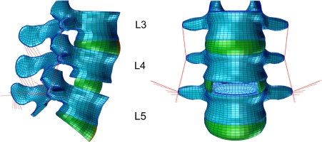
The L4/5 disc of the intact model was almost totally removed, leaving only the lateral parts of the annulus fibrosus in place (Fig. 1). The anterior and posterior longitudinal ligaments were transected. An artificial disc with a fixed center of rotation (similar to Prodisc) was integrated in a central position. A perfect bond was assumed between the prosthetic endplates and the adjacent vertebrae. No friction was simulated within the artificial disc. The artificial disc was modeled by the use of kinematic coupling [20, 25], simulating an idealized behavior of the implant. This method was realized with connector elements, which keep the nodes of the adjacent endplates at the allowed kinematics. The spinal kinematics are only slightly different from those obtained when modelling the disc implant conventionally with volumetric elements. Kinematic coupling strongly reduces the model modification time in parameter and probabilistic studies as well as the computer time for finite element analyses. However, it does not allow lift-off in the implant. Furthermore, it does not take into account implant deformations and hence it does not allow calculation of the stresses in the implant. Stresses calculated in the bone close to the implant are very often imprecise. The disc modeled allowed unlimited rotational motions.
Fig. 1.
Finite element model with artificial disc at level L4/5
Boundary and loading conditions
The inferior side of the L5/S1 intervertebral disc was rigidly fixed. The L3 vertebra was loaded with pure moments of 7.5 Nm in the three main anatomical planes to simulate flexion, extension, lateral bending to the right, and left axial torsion [24].
Probabilistic study
In the probabilistic study, the following five input variables were randomized simultaneously.
Position of the artificial disc in anterio-posterior direction (ap-position): A truncated Gaussian distribution with a mean value of 0 mm and a standard deviation of 1 mm was assumed. The range was limited to 3 mm from the central position in both directions.
Position of the artificial disc in lateral direction: Also in lateral direction, a truncated Gaussian distribution with a mean value of 0 mm and a standard deviation of 1 mm was assumed. The range was limited to 3 mm from the central position in both directions.
Radius of the implant ball: For the implant ball, a radius lying within a range between 5 and 20 mm was assumed. The radii of the current implant types are within this range. A uniform distribution of the radii was simulated. With increasing implant ball radius, the center of rotation of the artificial disc moves caudally to keep the most cranial point of the implant ball at the same position.
Gap size of the facet joints: A truncated Gaussian distribution with a mean value of 0.5 mm and a standard deviation of 0.3 mm were assumed. The range allowed was between 0.1 and 1.5 mm.
Scar tissue replacing the ALL: Only the two cases ‘scar tissue’ and ‘no scar tissue’ were allowed. Equal distribution of the two cases was simulated. The scar tissue had the same width and stiffness as the intact ALL.
The Monte Carlo method was used to generate randomized input parameters and 1,000 finite element calculations were performed for each of the four loading cases. The program NESSUS (Southwest Research Institute, San Antonio, Texas, USA) was employed to randomize and calculate probabilistic results. In a preliminary study, random samples of 100 calculations already led to similar probability distributions as did the 1,000 calculations while there were only minor differences between 500 and 1,000 random samples.
Output parameters of the probabilistic study were intervertebral rotations in the loading plane, intradiscal pressure and contact forces in the facet joints at all levels. Lateral bending and axial rotation causes different loads in the left and right facet joint. The higher value is always shown in this study. Scatter diagrams and curves for the cumulated probability are presented. The finite element program ABAQUS, version 6.7 (SIMULIA Inc., Providence, Rhode Island, USA), was used with the pre- and post-processor PATRAN (MSC Software, Marburg, Germany).
Results
Intervertebral rotations
The levels adjacent to the artificial disc were seen to be only slightly affected by the various input parameters for all loading cases studied.
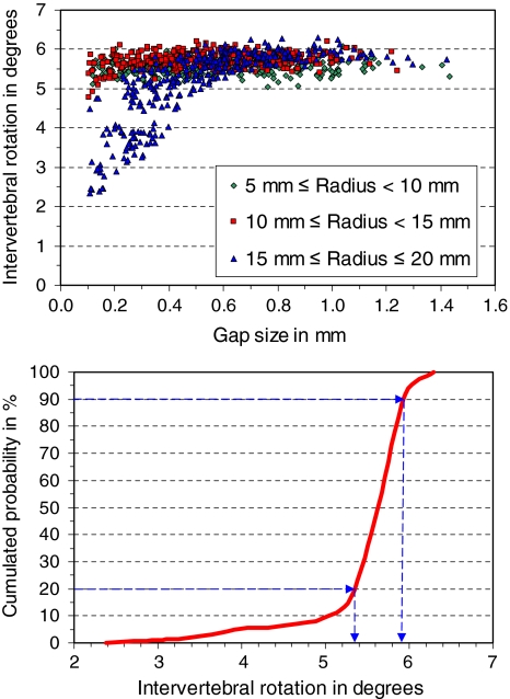
At the implant level, intervertebral rotation during flexion varies between 2.4° and 6.4° (Fig. 2). In 20% of the cases, the rotation is less than 5.35° and in 90% less than 5.9°. That means that intervertebral rotation is between 5.35° and 5.9° in 70% of the cases. Intervertebral rotation is mainly influenced by gap size, ap-position, and implant ball radius. Values of less than 5.0° are predicted for gap sizes less than 0.5 mm in combination with implant ball radii greater than 14 mm.
Fig. 2.
Scatter diagram (top) and cumulated probability of intervertebral rotation at implant level for loading case flexion (bottom). In the scatter diagram, intervertebral rotations are shown for 1,000 input parameter combinations depending on facet joint gap size and implant radius. In the lower diagram the cumulated probability of intervertebral rotation is given. It shows that in 20% of the cases intervertebral rotation is less than 5.35° and in about 70% it is between 5.35° and 5.9°
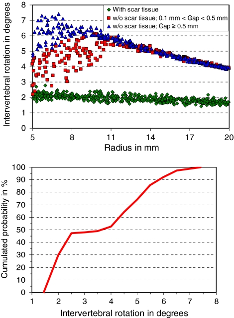
For extension, the intervertebral rotation varies between 1.4° and 7.5° (Fig. 3). In nearly 50% of all cases, it is less than 2.5°. These are the cases where scar tissue is assumed to be present. Implant ball radius has a small effect on intervertebral rotation. A larger radius leads normally to smaller rotations. Without scar tissue, intervertebral rotation is mostly greater than 4.0°. For implant ball radii greater than 11 mm there is nearly a linear decrease of intervertebral rotation. A small implant ball radius in combination with no scar tissue and large gaps in the facet joints leads to the highest rotations.
Fig. 3.
Scatter diagram (top) and cumulated probability of intervertebral rotation at implant level for loading case extension (bottom). In the scatter diagram the influence of implant radius, presence of scar tissue and gap size of the facet joint on intervertebral rotation is shown
For lateral bending, intervertebral rotation varies between 4.0° and 7.0°. In 40% of the cases, the rotation is less than 4.8°, and in another 40%, the rotation is greater than 5.8°. Intervertebral rotation is mainly affected by scar tissue and implant ball radius. If there is scar tissue, intervertebral rotation is low. The rotation decreases with increasing implant ball radius.
For axial torsion, intervertebral rotation varies between 0.6° and 2.8°. It is mainly affected by gap size and implant ball radius. Intervertebral rotation increases with increasing gap size and increasing implant ball radius.
Intradiscal pressure
Intradiscal pressure in the adjacent discs was only slightly affected by the input parameters. This is the case for all loading cases studied.
Forces in the facet joints
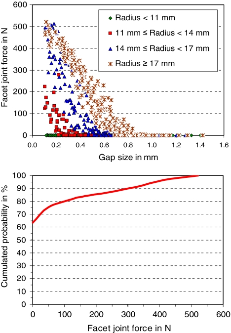
For flexion, contact forces in the facet joints at the levels adjacent to the artificial disc are zero for all combinations of the input parameters. At the implant level, the force varies between 0 and 533 N. In 63% of the cases, the force is zero (Fig. 4). Gap size and implant ball radius are the variables which mostly affect facet joint force. Forces are zero for facet joint gaps greater than 1 mm as well as for implant ball radii smaller than 11.5 mm. Forces greater than 400 N are only predicted for gaps less than 0.3 mm.
Fig. 4.
Scatter diagram (top) and cumulated probability of facet joint force for loading case flexion (bottom). In 63% of the cases the facet joint force was zero
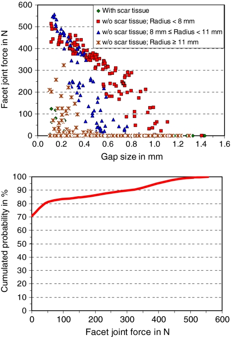
For extension, facet joint forces are about 13 N at level L3/4 and about 29 N at level L5/S1 for all combinations of the input parameters. At the level of the artificial disc, facet joint force varies between 0 and 560 N (Fig. 5). In 70% of the cases, the force is zero. Facet joint forces are mainly influenced by gap size, implant ball radius and scar tissue. High forces are predicted for combinations of small implant ball radii, small gap sizes and no scar tissue. Forces higher than 400 N are only calculated for gaps less than 0.4 mm in combination with no scar tissue.
Fig. 5.
Scatter diagram (top) and cumulated probability of facet joint force for loading case extension (bottom)
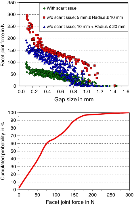
For lateral bending, facet joint forces are about 8 N at level L3/4 and 35 N at level L5/S1 for all combinations of the input parameters. At implant level, the force varies between 0 and 300 N (Fig. 6). The forces are mainly influenced by gap size, scar tissue and implant ball radius. When scar tissue is assumed, facet joint forces are less than 100 N. Forces higher than 200 N are predicted only for gaps less than 0.3 mm in combination with an implant ball radius less than 10.5 mm.
Fig. 6.
Scatter diagram (top) and cumulated probability of facet joint force for loading case lateral bending (bottom)
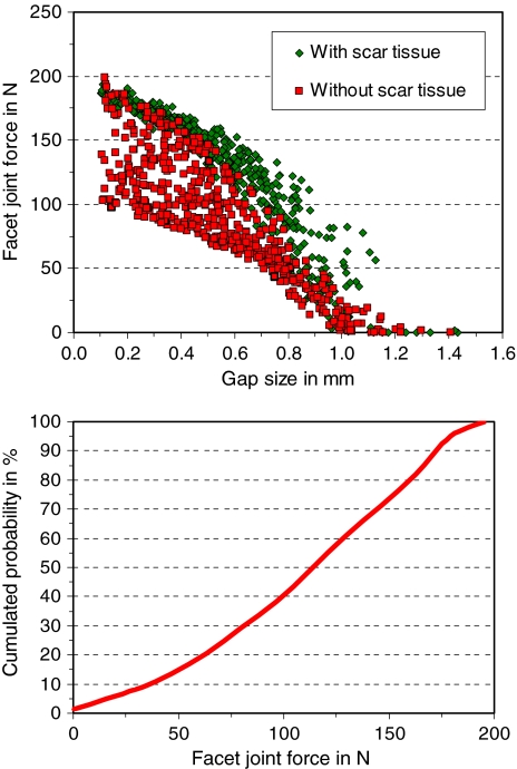
For axial torsion, facet joint forces are about 85 N at level L3/4 and 48 N at level L5/S1 for all combinations of the input parameters. At the level of the artificial disc, the forces vary between 0 and 200 N (Fig. 7). Forces are mainly affected by gap size, scar tissue and implant ball radius. High forces are predicted for a small gap, existence of scar tissue and a small implant ball radius with the gap size being the most influencing factor. Forces greater than 120 N are predicted for gaps less than 0.55 mm when there is no scar tissue and for gaps less than 0.85 mm when there is scar tissue.
Fig. 7.
Scatter diagram (top) and cumulated probability of facet joint force for loading case axial torsion (bottom)
Discussion
In this probabilistic study, the effects of implant position, implant ball radius, gap size in the facet joints and existence of scar tissue on intervertebral rotations, intradiscal pressures and contact forces in the facet joints were determined.
Although being quite extensive, this study still has some limitations. The large number of possible input variables disallows to study all combinations of them. Only one spine geometry was studied although the geometry may significantly affect some results. Using patient-specific models would drastically increase the computer time needed for the calculations. It is presently also practically impossible to validate these models. The vertebrae were assumed to be rigid although in reality they would deform under loading. Pure moments were applied to simulate the motion of the spine, and muscle forces were neglected. Only one type of artificial disc was studied. The artificial disc with a fixed centre of rotation was simulated assuming kinematic coupling thus not allowing elastic deformations within the disc. Lift-off in the disc may occur when facets come to contact or the range of motion of the implant is exceeded. Our kinematic model did not allow lift-off. Only one stiffness was assumed for the scar tissue. Due to these and other simplifications, the calculated absolute values are not necessarily very precise. The calculated trends, however, should be affected only slightly by these assumptions.
The levels adjacent to the artificial disc were basically unaffected by the various input parameters. This is due to the load-controlled loading protocol. The applied loads were always the same, and this assured that all levels see the same moment. A motion-controlled protocol with a pre-determined motion would have had an effect on the adjacent levels depending among others on the number of model segments. This dependency is one reason why motion-controlled loading protocols are seldom used. It is still a matter of debate, which loading protocol is the most realistic one.
For flexion, intervertebral rotation was among 70% of the cases between 5.35° and 5.9°. Lower values were calculated for small facet joint gaps in combination with large implant ball radii. A large implant ball radius leads to apparent translation of the cranial vertebra in anterior direction. This reduces the gap in the facet joints and thus the possible range of motion at that level. The contact forces in the facet joints were zero in 63% of the cases. For small gaps in combination with large implant ball radii, the forces increased up to 533 N. Apparent translation in the anterior direction of the cranial vertebra relative to the caudal vertebra—in the case of a large implant ball radius as well as a small gap—leads to early contact in the facet joints and thus to high contact forces.
For extension, intervertebral rotation is mainly affected by scar tissue. If it is present, the rotation is small. Without scar tissue the rotation was much higher. This demonstrates the importance of ALL and scar tissue for limiting rotation during extension. The greatest rotations were predicted when no scar tissue was assumed in combination with small implant ball radii and large gaps in the facet joints. A large gap allows greater rotations prior to contact in the facet joint. In the case of small implant ball radius, the center of rotation is close to the natural center of rotation. Facet joint forces were zero in 70% of the cases. Small implant ball radii, small gaps in the facet joints and the absence of scar tissue led to contact forces of up to 560 N. A small implant ball radius and a small facet joint gap lead to early contact and high forces in the facet joints. The absence of scar tissue increases intervertebral rotation and thus has a similar effect to that of a small implant ball radius.
It is remarkable that for flexion and extension, calculated facet joint forces were zero in about two-thirds of the cases but higher than 400 N in about 5% of the cases. Very high contact forces may lead to facet joint arthrosis and thus to low back pain.
For lateral bending, intervertebral rotation is affected mainly by scar tissue and implant ball radius. The scar tissue was assumed to have the same lateral dimension as the ALL. Therefore, it is effective also for lateral bending. With increasing implant ball radius, the apparent translation also increases, and this reduces the gap, thus leading to smaller rotations. Facet joint forces are mainly affected by gap size, scar tissue and implant ball radius. When scar tissue was present, intervertebral rotation and thus facet joint forces were small. Forces up to 300 N were predicted for small gaps in combination with small implant ball radii since both lead to early contact in facet joints.
Intervertebral rotation is small for axial torsion and affected mainly by gap size and implant ball radius. A small gap leads to earlier contact in the facet joints, which reduces intervertebral rotation. Axial torsion is accompanied by coupled motion in the frontal plane. Therefore, also the implant ball radius affects intervertebral rotation for axial torsion. Facet joint forces are mainly affected by gap size, scar tissue and implant ball radius. A small gap and a small radius close the gap earlier and therefore cause higher contact forces in the facet joint.
Intradiscal pressure was only slightly influenced by the various input parameters studied. Thus this global parameter is not very sensitive to these input parameters. Intradiscal pressure is mostly influenced by the axial spinal load [17].
For flexion, higher facet joint forces are predicted for large ball radii than for small ones. For extension, lateral bending and axial rotation it is the other way round. Joint kinematics may significantly alter as facets come to contact and thereafter as this articulation continues. This may lead to lift-off in the disc that reduces the force increase in the facet joints. Lift-off occurs easier in implants with large ball radii than with small ones. On the other hand, a small ball radius develops high resistance against lift-off that leads to high shear forces at the interface between implant and vertebral endplates during axial rotation. Lift-off in the disc may damage the articulating surfaces and increase the wear rate. Thus both, high facet joint forces and lift-off in the implant are potentially harmful for the patient. A model that prevents lift-off in the implant may overestimate the contact force in the facet joint.
For the loading cases chosen, the position of the implant revealed in most cases only a minor effect on the output variables studied. This seems to be in contradiction to earlier studies [12, 19, 20, 26] where a considerable effect of implant position had been predicted. However, effects of implant position found in the present study are small in relation to the influence of the other input parameters studied.
This study shows that intervertebral rotation and contact force in the facet joints can vary widely depending on implant ball radius, gap size of facet joint and presence of scar tissue. Some combinations of the input variables may lead to very high forces in the facet joints that may cause facet joint arthrosis and subsequently low back pain. Further studies will be necessary in order to prove that artificial discs with extreme implant ball radii may thus lead more often to clinical problems in patients with small facet joint gaps but without scar tissue.
Acknowledgment
The study was financially supported by the Deutsche Forschungsgemeinschaft, Bonn, Germany (Ro 581/17-2).
References
- 1.Cramer GD, Gregerson DM, Knudsen JT, Hubbard BB, Ustas LM, Cantu JA (2002) The effects of side-posture positioning and spinal adjusting on the lumbar Z joints: a randomized controlled trial with sixty-four subjects. Spine 27:2459–2466. doi:10.1097/00007632-200211150-00008 [DOI] [PubMed]
- 2.Dar FH, Meakin JR, Aspden RM (2002) Statistical methods in finite element analysis. J Biomech 35:1155–1161. doi:10.1016/S0021-9290(02)00085-4 [DOI] [PubMed]
- 3.David T (2007) Long-term results of one-level lumbar arthroplasty: minimum 10-year follow-up of the CHARITE artificial disc in 106 patients. Spine 32:661–666. doi:10.1097/01.brs.0000257554.67505.45 [DOI] [PubMed]
- 4.Dooris AP, Goel VK, Grosland NM, Gilbertson LG, Wilder DG (2001) Load-sharing between anterior and posterior elements in a lumbar motion segment implanted with an artificial disc. Spine 26:E122–E129. doi:10.1097/00007632-200103150-00004 [DOI] [PubMed]
- 5.Eberlein R, Holzapfel GA, Schulze-Bauer CAJ (2000) An anisotropic model for annulus tissue and enhanced finite element analysis of intact lumbar disc bodies. Comput Methods Biomech Biomed Eng 4:209–229. doi:10.1080/10255840108908005
- 6.Goel VK, Grauer JN, Patel T, Biyani A, Sairyo K, Vishnubhotla S, Matyas A, Cowgill I, Shaw M, Long R, Dick D, Panjabi MM, Serhan H (2005) Effects of charite artificial disc on the implanted and adjacent spinal segments mechanics using a hybrid testing protocol. Spine 30:2755–2764. doi:10.1097/01.brs.0000195897.17277.67 [DOI] [PubMed]
- 7.Grauer JN, Biyani A, Faizan A, Kiapour A, Sairyo K, Ivanov A, Ebraheim NA, Patel T, Goel VK (2006) Biomechanics of two-level Charite artificial disc placement in comparison to fusion plus single-level disc placement combination. Spine J 6:659–666. doi:10.1016/j.spinee.2006.03.011 [DOI] [PubMed]
- 8.Haldar A, Mahadevan S (2000) Probability, reliability, and statistical methods in engineering design. Wiley, New York
- 9.Le Huec JC, Mathews H, Basso Y, Aunoble S, Hoste D, Bley B, Friesem T (2005) Clinical results of Maverick lumbar total disc replacement: two-year prospective follow-up. Orthop Clin North Am 36:315–322. doi:10.1016/j.ocl.2005.02.001 [DOI] [PubMed]
- 10.Mayer HM (2005) Total lumbar disc replacement. J Bone Joint Surg Br 87:1029–1037. doi:10.1302/0301-620X.87B8.16151 [DOI] [PubMed]
- 11.Mayer HM, Wiechert K, Korge A, Qose I (2002) Minimally invasive total disc replacement: surgical technique and preliminary clinical results. Eur Spine J 11(Suppl 2):S124–S130 [DOI] [PMC free article] [PubMed]
- 12.Moumene M, Geisler FH (2007) Comparison of biomechanical function at ideal and varied surgical placement for two lumbar artificial disc implant designs: mobile-core versus fixed-core. Spine 32:1840–1851. doi:10.1097/BRS.0b013e31811ec29c [DOI] [PubMed]
- 13.Nolte LP, Panjabi MM, Oxland TR (1990) Biomechanical properties of lumbar spinal ligaments. In: Heimke G, Soltesz U, Lee AJC (eds) Clinical implant materials, advances in biomaterials, vol 9. Elsevier, Heidelberg, pp 663–668
- 14.Panjabi MM, Oxland T, Takata K, Goel V, Duranceau J, Krag M (1993) Articular facets of the human spine. Quantitative three-dimensional anatomy. Spine 18:1298–1310. doi:10.1097/00007632-199308000-00009 [DOI] [PubMed]
- 15.Pitzen T, Kettler A, Drumm J, Nabhan A, Steudel WI, Claes L, Wilke HJ (2007) Cervical spine disc prosthesis: radiographic, biomechanical and morphological post mortal findings 12 weeks after implantation. A retrieval example. Eur Spine J 16:1015–1020. doi:10.1007/s00586-007-0312-3 [DOI] [PMC free article] [PubMed]
- 16.Rohlmann A, Bauer L, Zander T, Bergmann G, Wilke HJ (2006) Determination of trunk muscle forces for flexion and extension by using a validated finite element model of the lumbar spine and measured in vivo data. J Biomech 39:981–989. doi:10.1016/j.jbiomech.2005.02.019 [DOI] [PubMed]
- 17.Rohlmann A, Neller S, Claes L, Bergmann G, Wilke H-J (2001) Influence of a follower load on intradiscal pressure and intersegmental rotation of the lumbar spine. Spine 26:E557–E561. doi:10.1097/00007632-200112150-00014 [DOI] [PubMed]
- 18.Rohlmann A, Zander T, Bergmann G (2005) Comparison of the biomechanical effects of posterior and anterior spine-stabilizing implants. Eur Spine J 14:445–453. doi:10.1007/s00586-004-0784-3 [DOI] [PMC free article] [PubMed]
- 19.Rohlmann A, Zander T, Bergmann G (2005) Effect of total disc replacement with ProDisc on the biomechanical behavior of the lumbar spine. Spine 30:738–743. doi:10.1097/01.brs.0000157413.72276.c4 [DOI] [PubMed]
- 20.Rohlmann A, Zander T, Bock B, Bergmann G (2008) Effect of position and height of a mobile core type artificial disc on the mechanical behaviour of the lumbar spine. Proc Inst Mech Eng 222:229–239. doi:10.1243/09544119JEIM241 [DOI] [PubMed]
- 21.Rohlmann A, Zander T, Schmidt H, Wilke H-J, Bergmann G (2006) Analysis of the influence of disc degeneration on the mechanical behaviour of a lumbar motion segment using the finite element method. J Biomech 39:2484–2490. doi:10.1016/j.jbiomech.2005.07.026 [DOI] [PubMed]
- 22.Sharma M, Langrana NA, Rodriguez J (1995) Role of ligaments and facets in lumbar spinal stability. Spine 20:887–900. doi:10.1097/00007632-199504150-00003 [DOI] [PubMed]
- 23.Shirazi-Adl A, Ahmed AM, Shrivastava SC (1986) Mechanical response of a lumbar motion segment in axial torque alone and combined with compression. Spine 11:914–927. doi:10.1097/00007632-198611000-00012 [DOI] [PubMed]
- 24.Wilke HJ, Wenger K, Claes L (1998) Testing criteria for spinal implants: recommendations for the standardization of in vitro stability testing of spinal implants. Eur Spine J 7:148–154. doi:10.1007/s005860050045 [DOI] [PMC free article] [PubMed]
- 25.Zander T, Rohlmann A, Bergmann G (2006) Comparison of conventional and kinematic modeling of an artificial disc. In: 7th International symposium on computer methods in biomechanics and biomedical engineering. Antibes Juan Les Pins, France. ISBN 0-9549670-2-X
- 26.Zander T, Rohlmann A, Bock B, Bergmann G (2007) Biomechanische Konsequenzen von verschiedenen Positionierungen bewegungserhaltender Bandscheibenimplantate. Eine Finite-Elemente-Studie an der Lendenwirbelsäule. Orthopade 36:205–211. doi:10.1007/s00132-007-1056-9 [DOI] [PubMed]
- 27.Zander T, Rohlmann A, Calisse J, Bergmann G (2001) Estimation of muscle forces in the lumbar spine during upper-body inclination. Clin Biomech (Bristol, Avon) 16:73–80. doi:10.1016/S0268-0033(00)00108-X [DOI] [PubMed]


