

Abstract
Electron cryotomography was used to analyze the structure of the Lyme disease spirochete, Borrelia burgdorferi. This methodology offers a new means for studying the native architecture of bacteria by eliminating the chemical fixing, dehydration, and staining steps of conventional electron microscopy. Using electron cryotomography, we noted that membrane blebs formed at the ends of the cells. These blebs may be precursors to vesicles that are released from cells grown in vivo and in vitro. We found that the periplasmic space of B. burgdorferi was quite narrow (16.0 nm) compared to those of Escherichia coli and Pseudomonas aeruginosa. However, in the vicinity of the periplasmic flagella, this space was considerably wider (42.3 nm). In contrast to previous results, the periplasmic flagella did not form a bundle but rather formed a tight-fitting ribbon that wraps around the protoplasmic cell cylinder in a right-handed sense. We show how the ribbon configuration of the assembled periplasmic flagella is more advantageous than a bundle for both swimming and forming the flat-wave morphology. Previous results indicate that B. burgdorferi motility is dependent on the rotation of the periplasmic flagella in generating backward-moving waves along the length of the cell. This swimming requires that the rotation of the flagella exerts force on the cell cylinder. Accordingly, a ribbon is more beneficial than a bundle, as this configuration allows each periplasmic flagellum to have direct contact with the cell cylinder in order to exert that force, and it minimizes interference between the rotating filaments.
Spirochetes are a monophyltic phylum with a unique morphology (8, 35) These bacteria have a protoplasmic cell cylinder, which includes the plasma membrane and peptidoglycan layer, and an outer membrane. The region between the plasma membrane and the outer membrane constitutes the periplasmic space. The periplasmic flagella, which are subterminally attached to the ends of the protoplasmic cell cylinder, reside in this space. A given periplasmic flagellum is attached at only one end, extends toward the center of the cell, and is rotated by a basal motor anchored to the protoplasmic cell cylinder. The periplasmic flagella at each end form a group of filaments, and depending on the species, each group contains from one to hundreds of periplasmic flagella.
The motility of Borrelia burgdorferi, the Lyme disease spirochete, is quite complex (see references 10, 25, and 26 for recent reviews on spirochete motility). This species is capable of swimming both in low-viscosity media and also in viscous gel-like media that inhibit the motility of most other bacteria (19, 23). A typical B. burgdorferi cell runs, stops, flexes (pauses and forms a distorted shape), and reverses direction. Several lines of evidence indicate that during a run, the two groups of 7 to 11 periplasmic flagella rotate asymmetrically; i.e., one group rotates clockwise (CW), and the other rotates counter-clockwise (CCW) (10, 24, 32). (As a frame of reference, a given flagellum is viewed from its end along the filament toward its insertion into the protoplasmic cell cylinder.) A cell in the flexing mode is thought to have its groups of periplasmic flagella rotating in the same direction; i.e., either both rotate CW or both rotate CCW (32). During a running interval, the cell has a flat-wave appearance, with waves of constant amplitude being propagated from its anterior to its posterior end (19). Rotation of the two groups of periplasmic flagella in opposite directions generates backward-moving waves along the cell body that propel the cell forward (10, 18, 19, 19, 25; see http://stock.cabm.rutgers.edu/blast/video1.mov). B. burgdorferi has many motility and chemotaxis genes in common with those of rod-shaped bacteria (16, 25); it is chemotactic to many compounds, including glucosamine, N-acetylglucosamine, and glutamate (1). However, the paradigm for spirochete chemotaxis is notably different from that of other bacteria such as Escherichia coli and Salmonella enterica serovar Typhimurium (10). For example, B. burgdorferi rotates its groups of periplasmic flagella asymmetrically during a run (10, 24), whereas for E. coli and S. enterica serovar Typhimurium, all the flagella rotate CCW during the run (44). In addition, although CheY and CheA homologs are involved in B. burgdorferi chemotaxis (1, 24, 32), the nature of the signal that coordinates rotation of the two groups of periplasmic flagella is unknown (10).
The complex geometry of B. burgdorferi is beginning to be understood. B. burgdorferi cells are approximately 10 to 20 μm long and 0.33 μm in diameter (18, 19). The periplasmic flagella attached to one end of the cell are long enough to overlap with those of the other end (20). Because the cell cylinder is rod shaped in mutants that lack the periplasmic flagella and the flat-wave morphology is regained in genetically complemented strains that regain the periplasmic flagella, these organelles are concluded to have a skeletal function (31, 41). Purified periplasmic flagella are tightly coiled left-handed helices, with most having a helix pitch of 1.48 μm and a helix diameter of 0.28 μm (11). In addition, the periplasmic flagella undergo a helical transformation as a function of pH, as found with many flagella of other bacteria (S. Satoshi, S. I. Aizawa, M. Motaleb, and N. W. Charon, unpublished). In high-voltage electron micrographs of intact cells, the periplasmic flagella appear as a left-handed helical bundle with a helix pitch equal to the cell's wavelength (18). Although the bundle wraps around the body axis (i.e., the center of the cell cylinder, as if it were a sausage) in a right-handed sense, along the cell axis (i.e., since the cell resembles a sine wave, the cell axis is defined as an abscissa) it is left handed (18). Because the shapes of the isolated periplasmic flagella and cell cylinders are so markedly different from those seen in the intact cells, they evidently exert force on one another to influence each other's shape. Recent experiments and calculations using elasticity theory, coupled with measurements of the mechanical properties of purified periplasmic flagella and protoplasmic cell cylinders employing laser tweezers, indicate that the flat-wave cell morphology is a natural consequence of the interaction of helical periplasmic flagella and the rod-shaped cell cylinder (C. Dombrowski, W. Kan, M. A. Motaleb, N. W. Charon, R. E. Goldstein, and C. W. Wolgemuth, submitted for publication).
Cryoelectron microscopy and electron cryotomography, also referred to as cryoelectron tomography, offer a new methodology for studying the architecture of bacteria (22, 30, 45, 47). Previous electron microscopic analysis used specimens of cells that were chemically fixed and stained; this methodology has been shown to introduce artifacts. For example, electron microscopy of hydrated sections of E. coli and Pseudomonas aeruginosa indicated that the periplasmic space is markedly thinner than indicated by results previously obtained using fixed cells (28). Here we analyzed the structure of B. burgdorferi using electron cryotomography and compared our results to those recently reported for Treponema primitia and Treponema denticola (21, 34). We found not only that is its periplasmic space quite thin but that the periplasmic flagella do not form a bundle as previously thought (18, 31). Instead, the periplasmic flagella assemble into a very tightly packed flat ribbon that also widens the periplasmic space in the domain where they reside. Furthermore, we show how the ribbon configuration of the assembled periplasmic flagella is optimal for both swimming and forming the flat-wave morphology.
MATERIALS AND METHODS
Strains, culture conditions, and sample preparation.
The high-passage B. burgdorferi strain B31A was used for all analyses (6). Cells were grown in BSK complete medium (Sigma-Aldrich) at 34°C in an atmosphere of 3.0% CO2 (31). To prepare cells for electron cryotomography, approximately 1.5 ml of late-logarithmic-phase cells was centrifuged at 1,200 × g for 5 minutes in a microcentrifuge at room temperature. Approximately 1.4 ml of the supernatant fluid was discarded, and the cell pellet was gently resuspended by pipetting up and down in the remaining 100 μl and then cooled in ice. To prepare grids, first a thin carbon coat was evaporated onto Quantifoil electron microscopy specimen grids (R3.5/1; Quantifoil Microtools, Jena, Germany). The grids were immediately treated with a 10-nm colloidal gold solution to provide fiducial markers for alignment of the tomographic tilt series (36). Approximately 5 μl of the cell suspension was applied to the grid without dilution or washing. The excess medium was blotted with filter paper. The grid was immediately plunge-frozen into liquid ethane (13) and stored under liquid nitrogen for future examination.
Electron microscopy and tomographic reconstruction.
Images were recorded at −178°C, using a JEOL JEM4000FX instrument equipped with a Gatan GIF2002 energy filter. The microscope was operated at a 400-kV acceleration voltage in zero-loss energy-filtered mode. Single-axis tilt series were collected with a 1° increment and a 120° angular range. The thickness of the ice layer was 300 to 400 nm, as measured by electron energy-loss spectroscopy (14). The total electron dose for a tilt series was 70 to 90 e−/Å2, with the higher dose used with thicker specimens. The calculated resolution in the x-y plane was 8 nm. The calculated z (depth) resolution was 12 nm, due to the elongation factor from the “missing wedge” caused by the limited tilt range (37). The underfocus value, 15 μm, was chosen to maximize the transfer of information at the expected resolution limit in order to optimize the signal-to-noise ratio (29). All image processing was done using SPIDER (15), and the reconstructions were computed by weighted back-projection. Isosurface models were traced on a WACOM Cintiq 20WSX tablet (Wacom Co., Saitama, Japan) using AMIRA software (Mercury Computer Systems, Chelmsford, MA). To confirm chirality determinations, previously embedded Leptonema illini (formerly Leptospira illini), which is a known right-handed helical spirochete, was analyzed in the same manner as frozen B. burgdorferi cells (9, 18). The constructed images were originally found to be reversed from left to right (mirror images), and thus the final images as presented here were corrected for this reversal. A total of eight cells were analyzed, and measurements of specific parameters were made only from clearly defined images.
RESULTS
Overall cell morphology.
Electron cryotomography was used to analyze B. burgdorferi cells. Cells were propagated in growth medium, concentrated by centrifugation, dropped onto electron microscopy grids with a support film perforated with small holes, and immediately plunged into liquid ethane. Because the spirochetes are flexible, distortion of a cell occurred at the edges of the holes of the support film. The analyses we report are exclusively on those regions of the cells which fell across the holes. B. burgdorferi cells are considerably longer than the diameter of the grid holes. Consequently, only a relatively small region of the cell (2 to 3 μm, which is less than 25% of the cell length) was analyzed in a given tomogram.
The cells in general had a flat-wave appearance as seen in living or fixed cells. The large size of the spirochetes (peak-to-peak wave amplitude of approximately 780 nm [18]) and the shallow water layer (approximately 300 to 400 nm) resulted in the flat wave lying parallel to the grid. We compared the shape and diameter (dic) of the inner cell, as measured between the center of the plasma membrane at each side of the cell, in regions where the cell was curved (bend region) to those in regions that were more linear (interbend region). Our rationale is that bending of the cell could cause compression and distortion. Because the total cell diameter varied in the regions where the periplasmic flagella reside (see below), dic was used to test for compression. We found that there was no obvious distortion of the inner cell; all were circular. In addition, the dic was 285 ± 49 nm within the bends (n = 9 bends on seven cells), and 294 ± 35 nm in the interbend regions (n = 7 regions on seven cells). These results suggest that bending of the cells did not dramatically alter the inner diameter of the cell.
The general shape of the cells was similar in many respects to previous determinations using light microscopy, standard transmission electron microscopy, and high-voltage electron microscopy (18, 19). All cells appeared intact, with an attached outer membrane, plasma membrane, and periplasmic space, and the periplasmic flagella were clearly evident (Fig. 1 and 2a; see Movie S1 in the supplemental material). Cells were circular in cross section, with a diameter of approximately 310 nm in regions without periplasmic flagella, which compares reasonably well with results determined using high-voltage electron microscopy (330 nm) (18). At the ends of the cells, we often saw a bulb-like formation referred to as a bleb (Fig. 3). These blebs did not contain periplasmic flagella and had contents that appeared slightly denser than the cytoplasm. In addition, these structures were separated from the rest of the cell body and were continuous with the outer membrane.
FIG. 1.
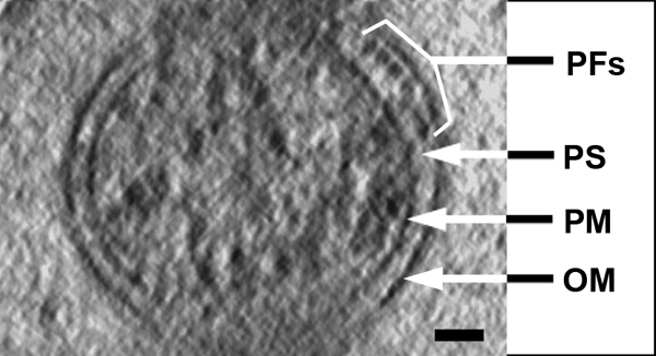
Electron cryotomography cross-section, 1.8 nm thick. The outer membrane (OM), plasma membrane (PM), periplasmic flagella (PFs), and periplasmic space (PS) are identified. Note the circular shape of the plasma membrane, the ribbon formation of the periplasmic flagella, and that the periplasmic space is wider in the domain where the periplasmic flagella reside. Bar, 50 nm.
FIG. 2.

(a) A 1.8-nm-thick longitudinal slice of a cell body. The outer membrane (OM), plasma membrane (PM), periplasmic flagella (PFs), and periplasmic space (PS) are identified. Bar, 200 nm. (b) Three-dimensional view of sections of a cell, showing that the periplasmic space (arrows) widens in the domain where the periplasmic flagella (red) reside. Blue represents plasma membrane, and brown represents outer membrane.
FIG. 3.
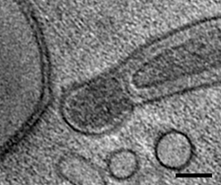
A 1.8-nm-thick longitudinal slice of a cell end. The ends of the cell were often bulb shaped. Bar, 100 nm.
Outer membrane and periplasmic space.
The outer membrane was noticeably different than that seen in chemically fixed and stained cells. While the outer membrane sometimes appears as having an irregular ruffled or uneven appearance in standard sections of fixed cells (see Fig. 3 in reference 18 and Fig. 4 in reference 31), it was quite smooth in appearance in the tomograms (Fig. 1 and 2a). The width of the periplasmic space was significantly greater in regions containing periplasmic flagella than in regions where there were no periplasmic flagella (Fig. 1 and 2a and b; see Movies S1 and S2 in the supplemental material). As measured between the centers of the outer membrane and plasma membrane, the width of the periplasmic space was 22.7 ± 3.9 nm in regions without periplasmic flagella (n = 17 spaces on eight cells) and 49.0 ± 6.9 nm in regions containing periplasmic flagella (n = 11 spaces on eight cells). The periplasmic space as measured between the inner and outer membranes was 16.0 ± 3.7 nm (n = 17 spaces on eight cells) in regions without the periplasmic flagella and 42.3 ± 6.8 nm (11 spaces on eight cells) in regions with the flagella.
FIG. 4.

A 9-nm-thick longitudinal slice of a cell end, showing four basal bodies in an approximately linear arrangement (arrowheads). The dark centers of the basal bodies are the regions where the filaments are seen to emanate by tomography. The putative peptidoglycan layer is indicated by the arrow. Bars, 200 nm in main image and 100 nm in inset.
Arrangement of basal bodies.
The basal bodies of the periplasmic flagella were evident only at the ends of the cells in a subterminal region (Fig. 4). The outer surfaces of the basal bodies (i.e., those parts of the basal bodies that directly face the periplasmic space), with the hook region exposed, were approximately 38 nm in diameter, which is similar to those reported for T. primitia (35 nm) but somewhat greater than those of T. denticola (29 nm) (21, 33). Each basal body appeared as a ring, with a dense region in the center. Flagellar filaments could be seen emanating from the dark center of the basal bodies and were seen to curve toward the center of the cell by tomography (not shown). The arrangement of basal bodies near the ends of the cell body was similar to that seen in negatively stained preparations as forming a somewhat linear arrangement parallel to the long axis of the cell (2, 7, 20), and they were found to lie along a line in the terminal bending region of the cell. The spacing between the four adjacent basal bodies as seen in Fig. 4 was approximately 90.8 ± 4.2 nm. In most tomograms, the peptidoglycan layer was not evident, but occasionally this putative wall layer was seen within the periplasmic space (Fig. 4).
Arrangement of the periplasmic flagella.
The periplasmic flagella were clearly visible in the tomograms, and their appearance was quite different than that seen in fixed cells. These organelles formed an elegantly constructed ribbon (Fig. 1, 2b, and 5a and b; see Movies S1, S2, and S3 in the supplemental material). The width of the ribbon was directly dependent on the number of periplasmic flagella and ranged from 92.9 nm to 160.9 nm, with a mean of 120.0 ± 26.7 nm (Fig. 6). The contribution of each periplasmic flagellum and surrounding region to the width of the ribbon was a mean of 19.2 ± 1.7 nm (range of 16.7 to 20.6 nm). Because previous results for unsheathed B. burgdorferi periplasmic flagella indicated a diameter of approximately 16 nm (20), evidently there is little space (3.0 nm or less) between neighboring periplasmic flagella within the ribbon. Significantly, the flat-ribbon formation by the periplasmic flagella is markedly different from that of stained and fixed cells. Previous results indicated that these structures formed a round bundle of 67 nm in diameter, and in thin sections they appeared as irregularly arranged filaments (18, 31). We found that an occasional filament was separated from the ribbon and was located on the opposite side of the cell cylinder (Fig. 2). In one ribbon of 158.27 nm that was composed of nine periplasmic flagella, one of the flagellar filaments in the middle region appeared to terminate. The space that it would occupy is evident in the tomogram; the remaining flagellar filaments moved to fill in the vacated space (Fig. 7). Specifically, the adjoining filaments are 19.0 nm apart at the point where the filament first disappears and 7.4 nm apart at a distance of 141 nm. These results suggest that there are forces acting on the filaments to bring the adjoining filaments together. In one case, we observed a wide ribbon close to the plasma membrane and another narrower ribbon with fewer filaments in one region close to the outer membrane (Fig. 2b). In all preparations, the ribbon wrapped around the body axis in a right-handed sense (Fig. 5a and b; see Movies S1, S2, and S3 in the supplemental material), which is in agreement with the high-voltage electron microscopy analysis (18). In addition, the angle subtended by the ribbon was approximately 1.13 rad in the interbend regions (Fig. 5a), which is also in agreement with the high-voltage electron microscopy analyses (18).
FIG. 5.

(a) A 1.8-nm-thick longitudinal slice of a ribbon of nine periplasmic flagella. The ribbon wraps around the cytoplasmic cylinder in a right-handed sense (bottom of cell as viewed from the top). Bar, 200 nm. (b) Three-dimensional view of sections of a cell, showing that the periplasmic flagella (red) form a ribbon and wrap around the cell cylinder (blue) in a right-handed sense. The outer membrane is not shown.
FIG. 6.
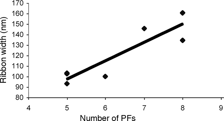
Ribbon formation. The width of the ribbons as a function of the number of periplasmic flagella (PFs) is shown. The coefficient of correlation was 0.90.
FIG. 7.
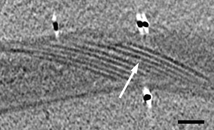
A 1.8-nm-thick longitudinal slice of a ribbon of nine periplasmic flagella. In this case, one of the flagella terminates (arrow) within the ribbon. Bar, 200 nm.
DISCUSSION
Electron cryotomography revealed that B. burgdorferi produced outer membrane blebs, and these structures were located at the ends of the cells. These blebs contained electron-dense material. B. burgdorferi is known to spontaneously generate membrane vesicles when grown in vitro and in vivo (12, 17, 37a). These vesicles, which are purified by passing culture supernatants though a 2-μm filter, are less than 0.25 μm in diameter and have been shown to contain DNA and several outer membrane-associated proteins, such as OspA and OspB, and an 83-kDa protein (12, 17, 43). In many species of bacteria, vesicles are postulated to play important roles in protein secretion, virulence, and promotion of cell-cell communication in biofilms (5, 27, 42). In B. burgdorferi, vesicles are believed to be able to readily penetrate tissues and initiate inflammation (43). Little is known about the precise details of how these structures are formed in other bacteria, but they are associated with the formation of blebs on the bacterial surface (27). In B. burgdorferi, we found that the blebs containing dense material are an extension of the outer membrane, which is in agreement with previous results of others using transmission electron microscopy (17). We find, however, that these blebs are located primarily at the ends of cells and not along the length of the cell as previously described (17).
The width of the periplasmic space in the region where no periplasmic flagella reside is consistent with what is found for T. denticola but less than in other gram negative bacteria. To compare our results with published values, we made two measurements. If we measured this space between the region of highest density of both the outer membrane and inner membrane, it was 22.7 nm. This is the easier measurement to make, because the region of the membrane of highest density is quite clear. On the other hand, if we just measured the space between the inner and outer membranes, it was considerably less, i.e., 16.0 nm. However, in this case, it is more difficult to determine the boundaries of the membrane, as some clarity is lost. When measuring between the outer and inner membranes, electron microscopy of ultramicrotome sections of frozen-hydrated cells revealed a periplasmic space of 24 nm for P. aeruginosa and 22 nm for E. coli (28), but as with our results, there was considerable variability. In T. denticola, the periplasmic space between the membranes was reported to be 15 to 22 nm (21), which is similar to our results with B. burgdorferi. For T. primitia, the periplasmic space was found to be 28 nm, as measured by the line of highest density between the membranes, which is somewhat wider than for B. burgdorferi. In T. primitia, two layers of wall are believed to be present in the periplasmic space (34), which is different from what is reported for B. burgdorferi.
The periplasmic space in B. burgdorferi contains the peptidoglycan layer, but we were not able to consistently visualize this structure, apparently due to its generally low density in this organism. Nevertheless, we know that peptidoglycan is present in these bacteria from chemical analyses, susceptibility to lysozyme after outer membrane disruption, and sensitivity to specific peptidoglycan wall-acting antibiotics (3, 39, 40, 46). Recent experiments suggest that the peptidoglycan of B. burgdorferi is quite flexible compared to sacculi from E. coli (Dombrowski et al., submitted), which may be related to a decrease in peptidoglycan cross-linking compared to that in other bacteria. In contrast to B. burgdorferi, both T. primitia and T. denticola have relatively rigid helical cell cylinders, and in both cases the peptidoglycan can be more readily visualized (21, 34, 38).
The periplasmic space in the vicinity where the periplasmic flagella reside was notably wider (42.3 nm) than in the region without these organelles (16.0 nm). Similar results of an increase width in the periplasmic space where the periplasmic flagella reside have been noted for T. primitia and T. denticola (21, 34). In T. denticola, the increase in width in this region was less than the diameter of the periplasmic flagella, and the suggestion was made that the peptidoglycan layer was thinner in that region. (21, 34). In contrast, in B. burgdorferi, this space is greater than the diameter of the periplasmic flagella (16 nm [20]). Therefore, our results suggest that the outer membrane fits tightly about the cell cylinder and that the periplasmic space widens due to the obstruction produced by the periplasmic flagella. In addition, in the bend regions of the cell, the periplasmic flagella may pull in toward the cell axis, causing the periplasmic space to widen more than the diameter of the filaments (see, for example, Fig. 3 in reference 18).
In contrast to the observations with plastic-embedded cells, which indicated that the periplasmic flagella form a bundle in the periplasmic space (31), electron cryotomography revealed that the periplasmic flagella form a tight ribbon in this space as they wrap around the cell cylinder. The periplasmic flagella are reported to have diameters of 16 nm (unsheathed) and 21 nm (sheathed) (20). The sheath is associated with FlaA, and it is localized proximal to the hook region (S. Shabata, S. Aizawa, M. Motaleb, and N. Charon, unpublished data). Given a diameter of 16 nm per filament, we estimate that there is approximately 3 nm between each filament in the ribbon. In addition, in agreement with the high-voltage electron microscopy of embedded cells (18), the ribbon was found to wrap around the body axis in a right-handed sense. These results indicate that each periplasmic flagellum is tightly associated with the cell cylinder, and thus each can equally participate in dictating the flat-wave morphology.
One obvious question is the following: how does the tight ribbon of periplasmic flagella form? Perhaps the spacing of the insertion of the periplasmic flagella is critical for ribbon formation, as these organelles are inserted on a line along the subterminal ends of the cell (2, 7, 20), which we find are approximately 90 nm apart. In addition, formation of the ribbon may depend on having active periplasmic flagella that rotate in a manner similar to bundle formation in E. coli and S. enterica (44). Previous results indicate that B. burgdorferi cells incubated in the cold or cells treated with the iononophore carbonyl cyanide-m-chlorophenylhydrazone, which dissipates the proton gradient, become immotile but still retain the flat-wave morphology (19, 31). One possible explanation for these results is that cells treated in this manner could have already formed the ribbon structure before treatment. Thus, flagellar rotation may be necessary to form but not maintain the ribbon structure. Although we precooled the cells in ice before preparing the grids, motile cells prepared without precooling still had the flat-ribbon configuration of the periplasmic flagella (J. Benach, T. LaRocca, M. Marko, and C. Hsieh, unpublished data). Thus, the ribbon configuration is not the result of cooling the cells in ice. We observed that if a filament is terminated before the others in a ribbon, the adjoining periplasmic flagella move to occupy the space. These results suggest that a force brings the periplasmic flagella together in a ribbon, and it may be that flagellar rotation helps produce this force. We expect that future experiments targeting genes that result in mutants that retain their periplasmic flagella but result in paralysis will allow us to determine the role of flagellar rotation and ribbon formation. Several questions remain unanswered. In Fig. 2, one of the periplasmic flagella is separated from the ribbon. Is this separation a consequence of that filament rotating in the opposite direction relative to the others? In addition, we observed that in one ribbon there was a region where there were two layers of ribbons. It is not known if the periplasmic flagella from one end form the double layer or if one layer is derived from the filaments from the other end. Finally, if most of the periplasmic flagella interact with the peptidoglycan layer as in a ribbon, how does an individual filament affect cell shape? Perhaps mutant analysis would allow the determination of how cell shape is influenced by the number of periplasmic flagella.
A final interesting question is the following: what role does this ribbon structure play in the motility of B. burgdorferi? We assume that the shape of the cell is explicitly tied to motility; i.e., optimal swimming is dependent on the flat-wave shape. Theoretical work on the morphology of B. burgdorferi suggests that the flat-wave shape depends strongly on the stiffness of the flagella compared to that of the cell cylinder (Dombrowski et al., submitted). If this model is correct, then there is a minimum number of flagella required to produce a flat-wave shape with a reasonable amplitude. If motility requires that the rotation of the flagella exerts force directly on the cell cylinder to generate the backward-moving flat waves, then a ribbon is clearly beneficial. As can be seen in Fig. 8a, and as is consistent with the results presented in this study, seven periplasmic flagella lie in a ribbon along the top side of the cell cylinder and rotate CCW. Each flagellum pushes against the cell cylinder to generate a backward-moving wave. This wave may be the result of the periplasmic flagella pushing against the cell cylinder with some slippage as they rotate. In addition, the torque generated may also cause a counter rotation of the cell cylinder (4, 10, 18, 19). Since each flagellum is in contact with the cell cylinder, each imparts an equal force and torque to the cell cylinder. Furthermore, since there is a small space between each flagellum, there is little interaction between the rotating flagella. Figure 8b represents what is observed in cells fixed in plastic (18, 31). The bundle configuration of flagella requires that some of the flagella are not in contact with the cell cylinder. For these flagella to exert an equal force and torque on the cell cylinder, their rotation must be conveyed to the cell cylinder through interaction with other flagella. However, the rotation of a flagellum that is in contact with another flagellum and rotating in the same direction impedes and interferes with the motion of the neighboring flagellum. Therefore, a bundle configuration would likely decrease the rotation of the flagella and lead to a smaller force and torque being applied to the cell cylinder. We expect that a detailed understanding of both ribbon formation and its physical interaction with the cell cylinder will lead to a more complete mechanical model of how flagellar rotation and wave deformations drive motility.
FIG. 8.

Cartoon comparison of the effectiveness of a periplasmic flagellar ribbon compared to that of a bundle. (a) Cross-sectional view of the ribbon configuration observed in electron cryotomography images. (b) Schematic of a bundle configuration of periplasmic flagella, which represents a configuration similar to that seen in plastic-embedded cells (18, 31). The cell body is gray, and its surface is dashed. The periplasmic flagella are rotating CCW. See text for details.
Supplementary Material
Acknowledgments
This research was supported by Public Health Service grant AI-29743 awarded to N.W.C., Public Health Service grant GM 0072004 awarded to C.W.W., Public Health Service grant AR054582 awarded to M.A.M., National Science Foundation grant DMS 0201063 to S.F.G., and Public Health Service grant P41 RR01219, which supports the Wadsworth Center's Resource for Biological Complexity as a National Biotechnological Resource.
We are grateful for resources from the University of Minnesota Supercomputing Institute. We also appreciate the unpublished information from S. I. Aizawa, S. Shibata. J. Benach, and T. LaRocca. We thank D. Dorward for helpful information.
Footnotes
Published ahead of print on 14 November 2008.
Supplemental material for this article may be found at http://jb.asm.org/.
REFERENCES
- 1.Bakker, R. G., C. Li, M. R. Miller, C. Cunningham, and N. W. Charon. 2007. Identification of specific chemoattractants and genetic complementation of a Borrelia burgdorferi chemotaxis mutant: a flow cytometry-based capillary tube chemotaxis assay. Appl. Environ. Microbiol. 731180-1188. [DOI] [PMC free article] [PubMed] [Google Scholar]
- 2.Barbour, A. G., and S. F. Hayes. 1986. Biology of Borrelia species. Microbiol. Rev. 50381-400. [DOI] [PMC free article] [PubMed] [Google Scholar]
- 3.Beck, G., J. L. Benach, and G. S. Habicht. 1990. Isolation, preliminary chemical characterization, and biological activity of Borrelia burgdorferi peptidoglycan. Biochem. Biophys. Res. Commun. 16789-95. [DOI] [PubMed] [Google Scholar]
- 4.Berg, H. C. 1976. How spirochetes may swim. J. Theor. Biol. 56269-273. [DOI] [PubMed] [Google Scholar]
- 5.Beveridge, T. J. 1999. Structures of gram-negative cell walls and their derived membrane vesicles. J. Bacteriol. 1814725-4733. [DOI] [PMC free article] [PubMed] [Google Scholar]
- 6.Bono, J. L., A. F. Elias, J. J. Kupko III, B. Stevenson, K. Tilly, and P. Rosa. 2000. Efficient targeted mutagenesis in Borrelia burgdorferi. J. Bacteriol. 1822445-2452. [DOI] [PMC free article] [PubMed] [Google Scholar]
- 7.Bourret, R. B., N. W. Charon, A. M. Stock, and A. H. West. 2002. Bright lights, abundant operons—fluorescence and genomic technologies advance studies of bacterial locomotion and signal transduction: review of the BLAST meeting, Cuernavaca, Mexico, 14 to 19 January 2001. J. Bacteriol. 1841-17. [DOI] [PMC free article] [PubMed] [Google Scholar]
- 8.Canale-Parola, E. 1984. The spirochetes, p. 38-70. In N. R. Krieg and J. G. Holt (ed.), Bergey's manual of systematic bacteriology. Williams and Wilkins, Baltimore, MD.
- 9.Carleton, O., N. W. Charon, P. Allender, and S. O'Brien. 1979. Helix handedness of Leptospira interrogans as determined by scanning electron microscopy. J. Bacteriol. 1371413-1416. [DOI] [PMC free article] [PubMed] [Google Scholar]
- 10.Charon, N. W., and S. F. Goldstein. 2002. Genetics of motility and chemotaxis of a fascinating group of bacteria: the spirochetes. Annu. Rev. Genet. 3647-73. [DOI] [PubMed] [Google Scholar]
- 11.Charon, N. W., S. F. Goldstein, S. M. Block, K. Curci, J. D. Ruby, J. A. Kreiling, and R. J. Limberger. 1992. Morphology and dynamics of protruding spirochete periplasmic flagella. J. Bacteriol. 174832-840. [DOI] [PMC free article] [PubMed] [Google Scholar]
- 12.Dorward, D. W., T. G. Schwan, and C. F. Garon. 1991. Immune capture and detection of Borrelia burgdorferi antigens in urine, blood, or tissues from infected ticks, mice, dogs, and humans. J. Clin. Microbiol. 291162-1170. [DOI] [PMC free article] [PubMed] [Google Scholar]
- 13.Dubochet, J., M. Adrian, J. J. Chang, J. C. Homo, J. Lepault, A. W. McDowall, and P. Schultz. 1988. Cryo-electron microscopy of vitrified specimens. Q. Rev. Biophys. 21129-228. [DOI] [PubMed] [Google Scholar]
- 14.Egerton, R. F. 1986. Electron energy-loss spectroscopy in the electron microscope. Plenum, New York, NY.
- 15.Frank, J., M. Radermacher, P. Penczek, J. Zhu, Y. Li, M. Ladjadj, and A. Leith. 1996. SPIDER and WEB: processing and visualization of images in 3D electron microscopy and related fields. J. Struct. Biol. 116190-199. [DOI] [PubMed] [Google Scholar]
- 16.Fraser, C. M., S. Casjens, W. M. Huang, G. G. Sutton, R. Clayton, R. Lathigra, O. White, K. A. Ketchum, R. Dodson, E. K. Hickey, M. Gwinn, B. Dougherty, J. F. Tomb, R. D. Fleischmann, D. Richardson, J. Peterson, A. R. Kerlavage, J. Quackenbush, S. Salzberg, M. Hanson, R. van Vugt, N. Palmer, M. D. Adams, and J. Gocayne. 1997. Genomic sequence of a Lyme disease spirochaete, Borrelia burgdorferi. Nature 390580-586. [DOI] [PubMed] [Google Scholar]
- 17.Garon, C. F., D. W. Dorward, and M. D. Corwin. 1989. Structural features of Borrelia burgdorferi—the Lyme disease spirochete: silver staining for nucleic acids. Scanning Microsc. Suppl. 3109-115. [PubMed] [Google Scholar]
- 18.Goldstein, S. F., K. F. Buttle, and N. W. Charon. 1996. Structural analysis of Leptospiraceae and Borrelia burgdorferi by high-voltage electron microscopy. J. Bacteriol. 1786539-6545. [DOI] [PMC free article] [PubMed] [Google Scholar]
- 19.Goldstein, S. F., N. W. Charon, and J. A. Kreiling. 1994. Borrelia burgdorferi swims with a planar waveform similar to that of eukaryotic flagella. Proc. Natl. Acad. Sci. USA 913433-3437. [DOI] [PMC free article] [PubMed] [Google Scholar]
- 20.Hovind-Hougen, K. 1984. Ultrastructure of spirochetes isolated from Ixodes ricinus and Ixodes dammini. Yale J. Biol. Med. 57543-548. [PMC free article] [PubMed] [Google Scholar]
- 21.Izard, J., C. E. Hsieh, R. J. Limberger, C. A. Mannella, and M. Marko. 2008. Native cellular architecture of Treponema denticola revealed by cryo-electron tomography. J. Struct. Biol. 16310-17. [DOI] [PMC free article] [PubMed] [Google Scholar]
- 22.Jensen, G. J., and A. Briegel. 2007. How electron cryotomography is opening a new window onto prokaryotic ultrastructure. Curr. Opin. Struct. Biol. 17260-267. [DOI] [PubMed] [Google Scholar]
- 23.Kimsey, R. B., and A. Spielman. 1990. Motility of Lyme disease spirochetes in fluids as viscous as the extracellular matrix. J. Infect. Dis. 1621205-1208. [DOI] [PubMed] [Google Scholar]
- 24.Li, C., R. G. Bakker, M. A. Motaleb, M. L. Sartakova, F. C. Cabello, and N. W. Charon. 2002. Asymmetrical flagellar rotation in Borrelia burgdorferi nonchemotactic mutants. Proc. Natl. Acad. Sci. USA 996169-6174. [DOI] [PMC free article] [PubMed] [Google Scholar]
- 25.Li, C., M. A. Motaleb, M. Sal, S. F. Goldstein, and N. W. Charon. 2000. Spirochete periplasmic flagella and motility. J. Mol. Microbiol. Biotechnol. 2345-354. [PubMed] [Google Scholar]
- 26.Limberger, R. J. 2004. The periplasmic flagellum of spirochetes. J. Mol. Microbiol. Biotechnol. 730-40. [DOI] [PubMed] [Google Scholar]
- 27.Mashburn-Warren, L. M., and M. Whiteley. 2006. Special delivery: vesicle trafficking in prokaryotes. Mol. Microbiol. 61839-846. [DOI] [PubMed] [Google Scholar]
- 28.Matias, V. R., A. Al-Amoudi, J. Dubochet, and T. J. Beveridge. 2003. Cryo-transmission electron microscopy of frozen-hydrated sections of Escherichia coli and Pseudomonas aeruginosa. J. Bacteriol. 1856112-6118. [DOI] [PMC free article] [PubMed] [Google Scholar]
- 29.McEwen, B. F., M. Marko, C. E. Hsieh, and C. Mannella. 2002. Use of frozen-hydrated axonemes to assess imaging parameters and resolution limits in cryoelectron tomography. J. Struct. Biol. 13847-57. [DOI] [PubMed] [Google Scholar]
- 30.Morris, D. M., and G. J. Jensen. 2008. Toward a biomechanical understanding of whole bacterial cells. Annu. Rev. Biochem. 77583-613. [DOI] [PubMed] [Google Scholar]
- 31.Motaleb, M. A., L. Corum, J. L. Bono, A. F. Elias, P. Rosa, D. S. Samuels, and N. W. Charon. 2000. Borrelia burgdorferi periplasmic flagella have both skeletal and motility functions. Proc. Natl. Acad. Sci. USA 9710899-10904. [DOI] [PMC free article] [PubMed] [Google Scholar]
- 32.Motaleb, M. A., M. R. Miller, C. Li, R. G. Bakker, S. F. Goldstein, R. E. Silversmith, R. B. Bourret, and N. W. Charon. 2005. CheX is a phosphorylated CheY phosphatase essential for Borrelia burgdorferi chemotaxis. J. Bacteriol. 1877963-7969. [DOI] [PMC free article] [PubMed] [Google Scholar]
- 33.Murphy, G. E., J. R. Leadbetter, and G. J. Jensen. 2006. In situ structure of the complete Treponema primitia flagellar motor. Nature 4421062-1064. [DOI] [PubMed] [Google Scholar]
- 34.Murphy, G. E., E. G. Matson, J. R. Leadbetter, H. C. Berg, and G. J. Jensen. 2008. Novel ultrastructures of Treponema primitia and their implications for motility. Mol. Microbiol. 671184-1195. [DOI] [PMC free article] [PubMed] [Google Scholar]
- 35.Paster, B. J., and F. E. Dewhirst. 2000. Phylogenetic foundation of spirochetes. J. Mol. Microbiol. Biotechnol. 2341-344. [PubMed] [Google Scholar]
- 36.Penczek, P., M. Marko, K. Buttle, and J. Frank. 1995. Double-tilt electron tomography. Ultramicroscopy 60393-410. [DOI] [PubMed] [Google Scholar]
- 37.Radermacher, M., and W. Hoppe. 1980. Properties of 3-D reconstructions from projections from conical tilting compared to single-axis tilting, p. 132-133. In P. Brederoo and G. Boom (ed.), Proceedings of the 7th European Congress on Electron Microscopy, vol. 1. Seventh European Congress on Electron Microscopy Foundation, Leiden, The Netherlands. [Google Scholar]
- 37a.Radolf, J. D., K. W. Bourell, D. R. Akins, J. R. Brusca, and M. V. Norgard. 1994. Analysis of Borrelia burgdorferi membrane architecture by freeze-fracture electron microscopy. J. Bacteriol. 17621-31. [DOI] [PMC free article] [PubMed] [Google Scholar]
- 38.Ruby, J. D., H. Li, H. Kuramitsu, S. J. Norris, S. F. Goldstein, K. F. Buttle, and N. W. Charon. 1997. Relationship of Treponema denticola periplasmic flagella to irregular cell morphology. J. Bacteriol. 1791628-1635. [DOI] [PMC free article] [PubMed] [Google Scholar]
- 39.Sal, M. S., C. Li, M. A. Motalab, S. Shibata, S. Aizawa, and N. W. Charon. 2008. Borrelia burgdorferi uniquely regulates its motility genes and has an intricate flagellar hook-basal body structure. J. Bacteriol. 1901912-1921. [DOI] [PMC free article] [PubMed] [Google Scholar]
- 40.Sartakova, M., E. Dobrikova, and F. C. Cabello. 2000. Development of an extrachromosomal cloning vector system for use in Borrelia burgdorferi. Proc. Natl. Acad. Sci. USA 974850-4855. [DOI] [PMC free article] [PubMed] [Google Scholar]
- 41.Sartakova, M. L., E. Y. Dobrikova, M. A. Motaleb, H. P. Godfrey, N. W. Charon, and F. C. Cabello. 2001. Complementation of a nonmotile flaB mutant of Borrelia burgdorferi by chromosomal integration of a plasmid containing a wild-type flaB allele. J. Bacteriol. 1836558-6564. [DOI] [PMC free article] [PubMed] [Google Scholar]
- 42.Schooling, S. R., and T. J. Beveridge. 2006. Membrane vesicles: an overlooked component of the matrices of biofilms. J. Bacteriol. 1885945-5957. [DOI] [PMC free article] [PubMed] [Google Scholar]
- 43.Shoberg, R. J., and D. D. Thomas. 1993. Specific adherence of Borrelia burgdorferi extracellular vesicles to human endothelial cells in culture. Infect. Immun. 613892-3900. [DOI] [PMC free article] [PubMed] [Google Scholar]
- 44.Turner, L., W. S. Ryu, and H. C. Berg. 2000. Real-time imaging of fluorescent flagellar filaments. J. Bacteriol. 1822793-2801. [DOI] [PMC free article] [PubMed] [Google Scholar]
- 45.Wolgemuth, C., S. F. Goldstein, and N. W. Charon. 2008. Electron cryotomography reveals novel structures of a recently cultured termite gut spirochete. Mol. Microbiol. 671181-1183. [DOI] [PubMed] [Google Scholar]
- 46.Wormser, G. P., R. B. Nadelman, R. J. Dattwyler, D. T. Dennis, E. D. Shapiro, A. C. Steere, T. J. Rush, D. W. Rahn, P. K. Coyle, D. H. Persing, D. Fish, and B. J. Luft. 2000. Practice guidelines for the treatment of Lyme disease. Clin. Infect. Dis. 31(Suppl. 1)1-14. [DOI] [PubMed] [Google Scholar]
- 47.Zhang, P., C. M. Khursigara, L. M. Hartnell, and S. Subramaniam. 2007. Direct visualization of Escherichia coli chemotaxis receptor arrays using cryo-electron microscopy. Proc. Natl. Acad. Sci. USA 1043777-3781. [DOI] [PMC free article] [PubMed] [Google Scholar]
Associated Data
This section collects any data citations, data availability statements, or supplementary materials included in this article.