Abstract
A hybrid dose-computation method is designed which accurately accounts for multileaf collimator (MLC)-induced intensity modulation in intensity modulated radiation therapy (IMRT) dose calculations. The method employs Monte Carlo (MC) modeling to determine the fluence modulation caused by the delivery of dynamic or multisegmental (step-and-shoot) MLC fields, and a conventional dose-computation algorithm to estimate the delivered dose to a phantom or a patient. Thus, it determines the IMRT fluence prediction accuracy achievable by analytic methods in the limit that the analytic method includes all details of the MLC leaf transport and scatter. The hybrid method is validated and benchmarked by comparison with in-phantom film dose measurements, as well as dose calculations from two in-house, and two commercial treatment planning system analytic fluence estimation methods. All computation methods utilize the same dose algorithm to calculate dose to a phantom, varying only in the estimation of the MLC modulation of the incident photon energy fluence. Gamma analysis, with respect to measured two-dimensional (2D) dose planes, is used to benchmark each algorithm’s performance. The analyzed fields include static and dynamic test patterns, as well as fields from ten DMLC IMRT treatment plans (79 fields) and five SMLC treatment plans (29 fields). The test fields (fully closed MLC, picket fence, sliding windows of different size, and leaf-tip profiles) cover the extremes of MLC usage during IMRT, while the patient fields represent realistic clinical conditions. Of the methods tested, the hybrid method most accurately reproduces measurements. For the hybrid method, 79 of 79 DMLC field calculations have γ ≤1 (3% /3 mm) for more than 95% of the points (per field) while for SMLC fields, 27 of 29 pass the same criteria. The analytic energy fluence estimation methods show inferior pass rates, with 76 of 79 DMLC and 24 of 29 SMLC fields having more than 95% of the test points with γ ≤1 (3% /3 mm). Paired one-way ANOVA tests of the gamma analysis results found that the hybrid method better predicts measurements in terms of both the fraction of points with γ ≤1 and the average gamma for both 2% /2 mm and 3% /3 mm criteria. These results quantify the enhancement in accuracy in IMRT dose calculations when MC is used to model the MLC field modulation.
Keywords: IMRT, MLC, dose computation, Monte Carlo simulation, fluence
I. INTRODUCTION
Although the clinical advantages of highly conformal intensity modulated radiotherapy (IMRT) dose distributions have led to the widespread application of IMRT, improvements in the achievable accuracy in IMRT treatment-planning dose calculations have remained an investigational challenge.1 Routine IMRT quality assurance (QA) measurements in homogeneous phantoms are common practice for monitor unit (MU) and dose distribution verification and often indicate dose differences exceeding 5% in modulated regions of the treatment field.2 To achieve accurate dose calculations for IMRT, it is important to reduce the sources of such dose errors.
In general, the dose-computation process can be subdivided into two components: (1) Prediction of the radiation fluence incident upon the patient or the phantom and (2) prediction of the energy deposition caused by that fluence within the patient or the phantom. The accuracy in the estimation of the dose deposition is limited by the dose-computation algorithm used, particularly in relation to how it models the patient heterogeneities and the lateral spread of charged particles. For homogeneous treatment sites or geometries (phantoms), even radiological path-length correction methods may be adequate.3 When comparing measured and computed dose distributions in a homogeneous flat phantom, heterogeneity corrections in the dose-calculation algorithm should not affect the calculation accuracy, hence, observed dose deviations are a result of errors in the fluence prediction, errors in the dose spread within the phantom, or errors in measurements. For properly commissioned pencil beam (PB) and superposition/convolution (SC) algorithms, the lateral dose spread is adequately considered,3 leaving prediction of the incident energy fluence as a major cause of dose discrepancies.
In IMRT dose calculations, the energy fluence incident upon the patient/phantom can be expressed as an open-field (nonmodulated) energy fluence, combined with the energy fluence modulation caused by a field-shaping or modulating device, such as a multileaf collimator (MLC). While beam modeling and consequential fitting, at the time of commissioning of the treatment-planning system (TPS), allow accurate prediction of the open-field radiation fluence, the prediction of the MLC modulation requires additional modeling and validation. Several authors have described algorithms for converting MLC leaf-motion patterns into fluence-modification values for both multisegmential4,5 (step-and-shoot) and dynamic6-16 IMRT delivery. The accuracy of these algorithms varies with the complexity of the intensity modulation present in the IMRT field, with the rigor of the employed assumptions, and with the commissioning precision of the algorithm.
The computational schemes that model the modification of the incident fluence by the MLC for IMRT can be divided into analytic and Monte Carlo (MC) models. The analytic methods typically convert leaf positions (or trajectories) into (energy) fluence transmission maps (matrices) via techniques that are often called trajectory-to-fluence algorithms. The energy fluence transmission matrices are used to attenuate the primary nonmodulated (open field) incident energy fluence, which results in dose intensity modulation. The analytic algorithms often utilize simplifications in the MLC geometry when determining the MLC transmission factor and leaf-end modeling.4-9,11,14,15 Monte Carlo-based radiation-transport algorithms from the other hand can include detailed geometry description of the MLC and directly consider the impact of the MLC on the primary and scatter fluence on a particle-by-particle basis,6,10,12,13,16 hence producing an accurate representation of the fluence modulation produced by the MLC. The impact of the differences between the algorithms on the dosimetric accuracy would also be expected to depend upon the complexity of the IMRT fields and, correspondingly, the MLC leaf sequences.17
Analytic trajectory-to-fluence algorithms have developed in tandem with the development of IMRT. Early trajectory-to-fluence models9 did not incorporate scatter properties of the MLC, treating the collimator with an averaged transmission coefficient with no geometric corrections for the leaf shape and other technical leaf features, such as tongue-and-groove design or interleaf distance. The numerical algorithms developed for these models included the option for nonzero transmission of the MLC.7 Later developments8 provided a more general description which accounts for the tongue-and-groove leaf features present in most MLC designs. The MLC tongue-and-groove effect was studied14 through intensity map (transmission matrix) generation4 which were created4 by utilizing an analytic ray-tracing technique of the primary radiation through a detailed leaf geometry. The study concluded that the tongue-and-groove effect, in a single IMRT field, can be as high as 10% of the maximum dose in a given dose distribution. Although methods have been designed to minimize tongue-and-groove effects in leaf trajectories, these effects can not be entirely eliminated.11
In addition to the analytic methods, computationally more intensive MC-based MLC transport schemes were developed. These algorithms also evolved from simplified to more realistic modeling of the MLC geometry and the radiation transport physics. Studies with geant12 modeled the Varian 80-leaf MLC for photon-based dose computation. The leaf edges, parallel to the leaf motion, were modeled with the tongue-and-groove design, but the rounded leaf tips were approximated as planes focused on the source. This approximation required the use of an effective leaf-tip offset to the MLC positions to approximate the dosimetric effect of the rounded leaf ends. EGS418 component modules within BEAM19 were used to model MLCs, again, with geometry approximations.13 Using MCNP,20 a detailed study of the radiation transport through MLCs21 investigated MLC leakage and scatter using MC simulations. Due to the time intensiveness of full MC radiation transport through the MLC, particularly for dynamic IMRT, a clinically applicable MLC model for MC-based IMRT dose calculation and verification was developed,6 in which the problem of detailed MLC modeling was solved by subdividing the complex leaf geometry into simple geometrical regions. Only the primary and the first Compton scatter radiation were taken into account, while pair production and electron interactions were disregarded. In spite of these approximations the model was found to be accurate to within 1% or 1 mm for extreme and clinical test cases.
Detailed calculations, such as MC, are expected to most accurately estimate inter- and intraleaf scatter and attenuation, as shown in previous works comparing MC modeling of MLC scatter and leakage with respect to film-based measurements.6,10 While analytic methods of increasing complexity are expected to improve IMRT fluence prediction and hence agreement between predicted and measured IMRT dose distributions, in the end, the analytic methods are limited by the approximations made within. In the limit of including all details of the MLC geometry and of the incident particle fluence transport through the MLC in an analytic model, the analytic model itself becomes, in effect, a MC model.
This work introduces a hybrid computation method, which utilizes a detailed MC simulation of the accelerator head (BEAM19) and the MLC6 to predict the modulation of the energy fluence, incident upon a patient/phantom, and a conventional dose-computation algorithm to estimate the resultant dose within the patient/phantom. Thus, this hybrid method determines the IMRT fluence prediction accuracy, achievable by the analytic methods in the limit that the analytic method includes all details of the MLC leaf transport and scatter. The hybrid method is benchmarked by comparing in-phantom measured dose distributions with analytic methods of varying complexity, including those incorporated within the PINNACLE3 (Philips Medical Systems, Milpitas, CA) commercial TPS.
All of the computation methods, investigated in this study, employ the same dose-computation algorithm to calculate doses to a phantom. The only variable parameter is the estimation of the MLC modification of the incident photon energy fluence. Thus, the effect of the incident energy fluence prediction is isolated, independently of the dose-computation algorithm used. Therefore, the presented results directly quantify the achieved dosimetric improvements in the modeling of the MLC by a MC technique.
II. MATERIALS AND METHODS
A. Hybrid method
The hybrid method invokes MC transport to estimate the photon energy fluence modification caused by the MLC and, subsequently, utilizes an analytic dose-calculation algorithm to compute the dose in a phantom or a patient. A flow diagram, illustrating the functional operations of the MC transport through the MLC, is shown in Fig. 1. An incident phase-space of photons (particles), below the primary jaws, is created with the user code BEAM19 and is read by a distribution module (Box 1), although in general, any commissioned MC source algorithm could be utilized. Particles are simulated with and without intensity modulation. The particles transiting through the MLC are modeled (Box 2a) using an MC algorithm published in the literature.6 The modeling of the energy fluence incident on the patient plane in the absence of intensity modulation is presented in Fig. 1 (Boxes 2b and 3b). Particles, from the source, are transported in a vacuum to the isoplane. The isoplane includes the isocenter point and is perpendicular to the line connecting the isocenter and the accelerator target (z-direction). The nonmodulated particle is scored into an incident energy fluence matrix ψ0(xi, yi) (Fig. 1, Box 3b), according to its spatial coordinates xi and yi. The scoring matrix has a dimension of 40×40 cm2, projected at the isocenter, and is divided into 401×401 equally spaced bins, thus having a spatial resolution of 0.1×0.1 cm2. At the beginning of the simulation, all of the elements of that matrix are set to zero. For each particle, the appropriate bin of the matrix is updated according to Eq. (1)
| (1) |
where Ei is the energy, wi is the statistical weight, and xi and yi are the spatial coordinates on the isocenter plane of the ith simulated particle.
Fig. 1.
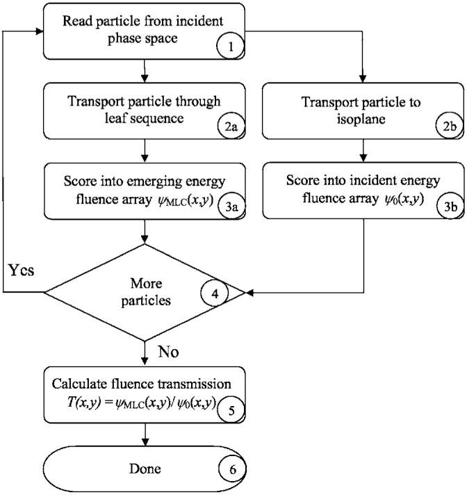
Flow diagram of the hybrid method used to determine the IMRT fluence modulation for a given MLC leaf sequence. See text for a detailed description of the process flow.
Fig. 2.
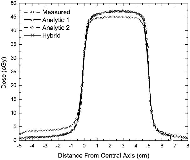
Measured and calculated profiles for 6 MV beam for the test case when the leaf tips are positioned on the central axis.
The modulated fluence modeling is outlined in Fig. 1 (Boxes 2a and 3a). Note that for each particle incident upon the MLC (Fig. 1, Box 2a), two particles can emerge: A primary and a scattered particle. Each exiting particle is scored into the emerging energy fluence matrix ψMLC(xi, yi) (Fig. 1, Box 3a), according to a procedure identical to the one for the nonmodulated particles [cf. Eq. (1)]. The emerging energy fluence matrix has the same dimensions and resolution as the nonmodulated energy fluence matrix and is also located at the isoplane.
The MC transport iterates over steps 1-3 to process all particles from the incident phase-space (Fig. 1, Box 4). Following completion of particle transport, the ratio of the modulated energy fluence to the nonmodulated energy fluence is computed (Fig. 1, Box 5) for each bin of the scoring matrices, thus forming an energy fluence transmission matrix Ti,j,
| (2) |
In case there are no incident particles scored in a particular bin (i, j) of the energy fluence transmission matrix, the denominator in Eq. (2) equals zero. Under these circumstances, the transmission coefficient Ti,j (for the bin of interest) is set to zero, thus preventing the unrealistic situation of infinite transmission. The resultant transmission matrix is utilized in the dose calculations according to Eq. (3)
| (3) |
where ψIncident on Patient(xi, yj) is the photon energy fluence incident upon the patient, and ψOpen Field(xi, yj) is the TPS photon energy fluence in the absence of MLC fluence modulation.
The hybrid method accounts for the effects of leaf transmission and scatter as well as inter- and intraleaf leakage. However, the information about the directional distribution of the scattered photons and the differential beam hardening12,21 of the photon beam, due to the MLC, is lost. The later facts are an inherent limitation of the transmission matrix approach with respect to MC particle-by-particle simulation approach.
The hybrid method can be used to calculate dose from arbitrary MLC leaf-motion profiles, including fixed MLC geometries and SMLC and DMLC IMRT fields. Furthermore, it can be used with an arbitrary dose-calculation algorithm. For the purposes of this study, it was linked to the SC dose-computation engines available in the PINNACLE3 TPS, with the intensity modulation imported as a transmission compensator matrix into the TPS.22 The integration was accomplished using Pinnacle’s scripting language, allowing the process to proceed automatically using a single button click from the TPS. Given the complete integration with the treatment-planning environment, this algorithm is presently applicable for routine IMRT patient calculations or pretreatment QA verification of IMRT delivery.
B. Analytic methods
Two in-house analytic methods (termed Analytic 1 and 2) were used to compute energy fluence transmission matrices Ti,j. The methods are based on a published analytic trajectory-to-fluence algorithm.7 Both methods estimate the total energy fluence transmission of beam rays integrated over the leaf motion, including open, closed, and rounded leaf-tip attenuation. In both methods, the head scatter and the finite source size are modeled with three Gaussian terms, in which the fitting parameters are determined by matching film dosimetry and ion chamber measurements. The tongue-and-groove leaf design is not modeled by either method, however, the average interleaf leakage is taken into account. In Analytic 1, the averaged rounded leaf-tip attenuation is modeled by incorporating the transmission through the actual leaf-tip shape, calculated for a leaf tip located on the central axis assuming a point source of radiation. In Analytic 2, the average rounded leaf-tip transmission was determined from published MC simulations,21 thus including source size effects and head-scattered photons in the leaf-tip transmission. The Analytic 2 method also includes an MC-derived term,21 that accounts for the scattered photons originating from the MLC leaves, which is not included in Analytic 1. The Analytic 1 method was used in previously reported dosimetric evaluations of clinically applied IMRT fields,23 while the Analytic 2 method was used as the basis of the DMLC IMRT module in PINNACLE3 V7.4 (and higher). In the implementation of the Analytic 2 method in PINNACLE3 (versions 7.4 and higher) an improvement was made, such that the TPS method included modeling of the tongue-and-groove leaf design.24
C. Method Validation
The hybrid method was validated with respect to in-phantom measurements and was compared with analytic algorithms of increasing complexity, including two in-house analytical algorithms clinically used at our institution, as well as with the analytic algorithms incorporated in PINNACLE3 v6.2b and PINNACLE3 v7.6c TPS. Measurements were taken with 6 and 18 MV photon fields, from a Varian (Varian Medical Systems, Palo Alto, California) 21EX accelerator equipped with a Millennium 120-leaf collimator, incident on a flat water-equivalent phantom (at 100 source-to-axis distance SAD, 5 cm depth). The test fields included fully blocked MLC (closed) field; static fields with every other MLC leaf crossing the beam aperture (picket-fence fields); sliding window (gap) fields with fixed aperture;6,21 and clinically derived DMLC and SMLC patient IMRT fields. Table I lists the test fields, as well as the computational algorithms with which the measurements were compared. For the clinically derived patient fields seventy nine DMLC IMRT fields were obtained from nine head-and-neck23 and one prostate DMLC IMRT treatments performed at our institution. The DMLC hybrid results were benchmarked with respect to the measurements, the two analytic methods (Analytic 1 and 2), and with PINNACLE3 v7.6c. The twenty nine SMLC IMRT fields were selected from four prostate patients and one head-and-neck patient treated in our clinic and planned with PINNACLE3 v6.2b. The SMLC IMRT hybrid results were benchmarked with respect to measurements, PINNACLE3 v6.2b and PINNACLE3 v7.6c computations.
Table I.
The fields (6 and 18 MV photons) used in the validation calculations are provided. A label is given for each test-field class, the jaw settings, the multileaf collimator (MLC) settings, the monitor units per field (MU), and the calculation method used. The calculation methods are indicated by letter abbreviations: Hybrid (HM), Analytic 1 (A1), Analytic 2 (A2), Pinnacle segmented multileaf collimator (SMLC) implemented in PINNACLE3 v6.2b (pinn v6.2b), and Pinnacle SMLC and sliding window (DMLC) implemented in PINNACLE3 v7.6c (pinn v7.6c).
| Label | Jaws (cm2) | MLC setup | MU | Calculation methods |
|---|---|---|---|---|
| Leaf tips | 10×24 | Leaf tips on CAX | 50 | HM, A1, A2 |
| Even teeth | 10×24 | odd retracted | 100 | HM, A1, A2 |
| Odd teeth | 10×24 | even retracted | 100 | HM, A1, A2 |
| Closed | 10×24 | closeda | 999 | HM, A1, A2 |
| Closed 5×5 | 5×5 | closed | 100 | HM, A1, A2 |
| Closed 10×10 | 10×10 | closed | 100 | HM, A1, A2 |
| Closed 15×15 | 15×15 | closed | 100 | HM, A1, A2 |
| Closed 20×20 | 20×20 | closed | 100 | HM, A1, A2 |
| Open | 10×10 | open | 100 | HM, A1, A2 |
| 1 mm gap | 13×10 | 1 mm sliding window | 100 | HM, A1, A2 |
| 10 mm gap | 13×10 | 1 cm sliding window | 100 | HM, A1, A2 |
| 100 mm gap | 13×10 | 10 cm sliding window | 100 | HM, A1, A2 |
| Clinical DMLC IMRT fieldsb | variable | field specific | Variable, 80-150 | HM, A1, A2, pinn v7.6c |
| Clinical SMLC IMRT fieldsc | variable | field specific | Variable, 80-150 | HM, pinn v6.2b, pinn v7.6c |
MLC leaves are blocking the field with the leaf tips positioned behind the jaws.
Total of 79 patient sliding window (DMLC) intensity modulated radiation therapy (IMRT) fields. 70 of these fields required split beams for delivery.
Total of 29 patient segmented multileaf collimator (SMLC) IMRT fields.
The film-based measurements were conducted by transferring the MLC sequences, in the form of MLC-controller instruction files, to a Varian 21EX MLC controller computer. The irradiated test films, Kodak XV2 ready-pack films (East-man Kodak Company, Rochester, New York), were placed at a source-to-film distance (SFD) of 100 cm, between two 5×30×30 cm3 polystyrene slabs. The MLC instruction files and machine settings used to deliver each beam were identical to those used in the calculations. For all measurements and calculations, the gantry (IEC system) and collimator angles were set to 0°. Film-calibration data were obtained during each measurement session by exposing 6 and/or 18 MV photon 10×10 cm2 open fields with monitor units (MU) varying from 0 to 90 MU, in 10 MU intervals. Calibration conditions were the same as those for the test-field measurements; films were placed at 5 cm depth with 5 cm of backscatter material at a 100 cm SFD. All measurement and calibration films used in a given measurement session were taken from the same box of film and processed sequentially in the same session to minimize the errors associated with variations in film lots and film-processing conditions. Processed films were scanned with a Vidar VXR 12+ film scanner into electronic image files. The optical density image files were analyzed with an in-house developed software, which converts the images into dose files, based on the optical densities from the calibration curves. The dose results were stored in 2D matrices with 0.2×0.2 cm2 resolution. Film localization was achieved by fiducial marks (derived by the accelerator light field) outside the field area on each film. The MUs used for the static and sliding window test fields (Table I) were chosen to give doses in the linear range (10-70 cGy) of the Kodak XV2 film. The SMLC and DMLC patient test fields had maximum doses in the 60-80 cGy range.
For each calculation, a dose grid of 0.2×0.2×1.0 cm3 was used, thus matching the film measurement geometry. The resultant doses computed with the hybrid method were compared with Analytic 1, Analytic 2, and PINNACLE3 v.7.6c calculated doses for DMLC IMRT fields and with PINNACLE3 v6.2b and PINNACLE3 v7.6c computed doses for SMLC IMRT fields.
Quantitative comparisons of the calculation-to-measurement results were performed by conducting gamma analyses, following the techniques described by several authors.25-27 The observed endpoints were the average gamma and the fractional number of points within each field with gamma less than one. Average gamma values for a given field were computed according to Eq. (4)
| (4) |
where M (typically ∼104) is the number of dose points in the planar dose image within a rectangular field defined by the primary jaws, and γj is the computed gamma value for each of these points. Two sets of dose difference and distance-to-agreement (DTA) acceptance criteria, namely 2% /2 mm and 3% /3 mm, were employed in the gamma analysis. Histogram data of the obtained results for all patient fields were generated for each beam delivery type (DMLC/SMLC).
For overall analysis, the average of the average gamma over all fields was calculated using Eq. (5),
| (5) |
where is the average gamma for the ith field and N is the number of fields (79 for the DMLC comparisons, and 29 for the SMLC comparisons). Similarly [cf. Eq. (5)], averages of the fraction of points with γ ≤1 were computed. One-way paired ANOVA analysis was performed to determine if the observed deviations between the hybrid method and each analytic method were statistically significant.
III. RESULTS
The 12 validation test fields (Table I) were designed to test the extrema of conditions that an MLC-modulated field may exhibit in a clinical operation. The “leaf-tip” field consists of a field collimated by the primary jaws to a 10×10 cm2 aperture, with the MLC leaves from one bank blocking one-half of the field, with the blocking leaves’ tips aligned to the central axis (CAX) of the field. A dose profile along the direction of travel of the leaves for this field is plotted in Fig. 2. The figure shows the dose in the open portion of the field (∼45 cGy, from 50 MU, 6 MV photons) on the right of the plot (positive distance from CAX) and the dose under the MLC (negative distance from CAX) on the left of the plot. Visual inspection of the dose profiles in Fig. 2 demonstrates that the Analytic 2 and the hybrid methods compare favorably with the measured dose profile.
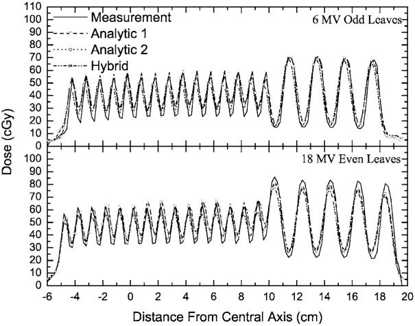
In the picket-fence fields, the primary jaws (set to 10×24 cm2, at 100 SAD) define a photon field, which is subsequently blocked by every other MLC leaf. Two variants of this approach were utilized, with even-numbered or odd-numbered MLC leaves blocking the radiation field. These two cases differ in that in one, the thicker portion of the (Varian 120 leaf MLC) leaf’s “T” shape is toward the target, while in the other it is toward the isocenter. This test provides the greatest challenge for the particle-tracking approximations implemented in the MC MLC model.6 Dose profiles perpendicular to the travel of the leaves are plotted in Fig. 3. Similar results were obtained, but are not plotted for the 6 MV “even” and 18 MV “odd” configurations. The dose profiles in Fig. 3 demonstrate that Analytic 1, Analytic 2, and the hybrid methods fit the measured dose profile, reproducing the features of peaks and valleys in the picket-fence-type irradiation field. However, the hybrid method outperforms the analytic methods, with gamma analysis (2% /2 mm criteria) results indicating that 81% of the points have γ ≤1 for the analytic methods, while more than 92% of the points have γ ≤1 for the hybrid method. Similarly, the results for the 3% /3 mm criteria show that the analytic methods have 92%-93% of the points with γ ≤1, while virtually all points (more than 99.2%) have γ ≤1 in the case of the hybrid method.
Fig. 3.
Measured and calculated profiles for selected picket-fence fields. The source-to-axis distance (SAD) of 100 cm is the same for both energies, while the depth for the 6 MV beam is 5 and 10 cm for the 18 MV beam.
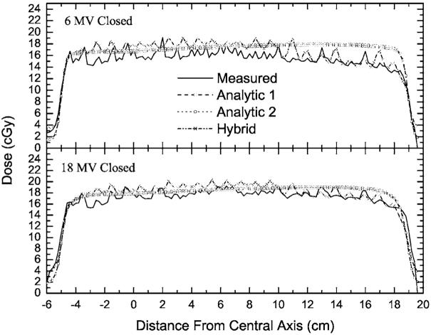
An investigation of intra- and interleaf leakage was conducted by using test fields in which the primary jaws (set again to 10×24 cm2, at 100 SAD) formed a field which was fully blocked by the MLC leaves. Such an MLC-blocked field represents an upper limit on the fractional contribution to the dose from radiation passing through, and scattered from, the MLC. Dose profile perpendicular to the direction of the leaves’ travel are plotted in Fig. 4, for a 6 MV beam (at a depth of 5 cm) and for an 18 MV beam (at a depth of 10 cm). The profiles are obtained by averaging a 9-voxel-wide (1.8 cm) rectangular strip (centered on the isocenter) in order to reduce the measurement noise. The same averaging was used for the calculated profiles. The measured dose undulations on the profiles (for 999 MU per field) were reproduced by the hybrid method, while they were not reproduced by the Analytic 1 or the Analytic 2 methods, since the later two methods do not account for differences between intra- and interleaf leakage. However, the average MLC leakage is predicted well by the analytic methods.
Fig. 4.
The measured and calculated profiles for a field completely blocked by the multi-leaf collimator (MLC). The source-to-axis distances (SADs) are the same as in Fig. 3. The depths for both energies are the same as the depths in Fig. 3.
The hybrid method reproduces the dose undulations, although the heights of these undulations vary from the measured undulations due to gap differences specific to each MLC. The reduction in the MLC transmission dose in the region where the thick (1 cm) leaves in the 120-leaf MLC are located (at distance grater than 10 cm from CAX) is also reproduced. In the thin leaf region (0.5 cm, between -5 cm and +10 cm), the dose predicted by the hybrid method is higher than the measured dose. Comparing the integral doses in the region from -4 cm to +9 cm (6 MV) shows that the hybrid method result is 8% higher than the measured result. However, the MLC transmission itself is only 1.6%-2.0%, thus, during an IMRT field delivered at an efficiency of 20% (five times the MUs required for a given dose compared with open-field delivery), the dose in the blocked region is less than 10% of the in-field dose. An 8% error in the dose on that 10% fraction corresponds to only a 0.8% error in terms of the in-field dose. Nonetheless, this quantity could be forced to match by slightly modifying the density of tungsten used within the MLC model.6,28 Similarly, between 10 and 18 cm (below the thick MLC leaves), the integral difference is 4%, corresponding to a less than 0.4% error in the in-field dose. Note that the Analytic 1 and 2 methods predict a constant transmission through the MLC bank, since they only account for the average transmission.
The effect of MLC scatter radiation on the MLC leakage is evaluated by measuring and computing the transmission through the closed MLC, while the primary jaws are set to square-field sizes ranging from 5×5 cm2 to 20×20 cm2 (Table I). The transmission is obtained by evaluating the ratio of the doses from these fields to their counterparts where the MLC is retracted6,21 (open). The results from these evaluations are plotted in Fig. 5 and are compared with benchmark ionization chamber measurements.21 Note that measurement data can not be obtained for fields wider than the maximum allowable leaf extension (14.5 cm), hence, the previously published MCNP20 MC calculations were utilized at all four field sizes (5×5 cm2 to 20×20 cm2) to provide a complete benchmark for all calculation settings. Calculations and measurements were averaged over the central 3×3 cm2 area to reduce the noise in the calculations (MC) and the measurement uncertainties. As can be seen from the plotted results, the Analytic 1 method does not predict well the average MLC leakage due to scatter, while all of the other methods agree well with the measurements.
Fig. 5.
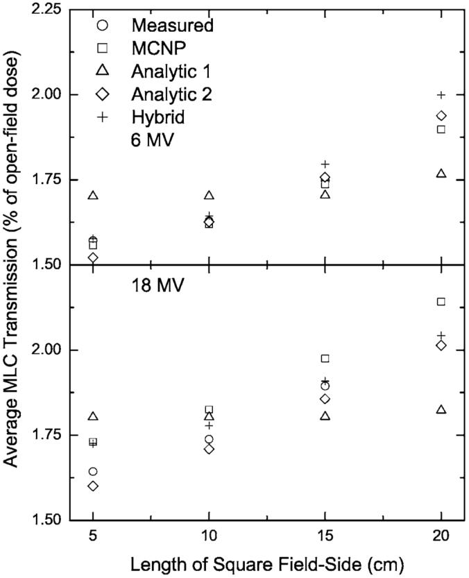
Measured and calculated leaf leakage for closed squared fields of different sizes. The leakage was averaged over the central 3×3 cm2 and normalized to the open-field dose, averaged in the same way.
Sliding window tests are generated by constant MLC opening that uniformly moves across a 10×10 cm2 field. The investigated window sizes were 1, 10, and 100 mm. In Table II, calculated and measured doses are compared for these sliding window tests. It has been shown that such tests are sensitive to the MLC leaf-tip contribution to the dose28,29 as well as to any leaf-positioning offsets or backlash.6 Also displayed in the table are the results of the closed-field tests. For the closed field, the maximum deviation from the measurements was 5% for Analytic 1 method, however, using the arguments presented above, this is acceptable because it corresponds to only 0.5% of the open-field dose for a typical IMRT field. The computation results from Analytic 2 method agree better with the closed-field measurement results, since the input data was adjusted to match the measurements. For the sliding windows, the hybrid method shows a 2.9% difference for the 1 mm gap field, while for larger gaps no difference is observed. The analytic methods, on the other hand, are severely challenged by the sliding window tests, which display a 15% difference for the 1 mm gap and a 6% difference for the 10 mm gap.
Table II.
Measured and computed doses at a depth of 5 cm in a phantom at 95 cm source-to-surface distance (SSD) for fields in which the multileaf collimator (MLC) was configured to block the entire radiation field (closed) and for fields created by sliding a window of the size indicated. The jaws are set to 10×10 cm2 for the closed field and 13×10 cm2 for the sliding window fields. Doses are given as percentages of the dose from a 10×10 cm2 open field.
| 6 MV |
18 MV |
|||||||
|---|---|---|---|---|---|---|---|---|
| Window width | Measured | Hybrid | Analytic 1 | Analytic 2 | Measured | Hybrid | Analytic 1 | Analytic 2 |
| Closed | 1.64 | 1.69 | 1.72 | 1.63 | 1.74 | 1.80 | 1.80 | 1.71 |
| 1 mm | 4.71 | 4.85 | 4.24 | 4.03 | 4.98 | 5.07 | 4.33 | 4.22 |
| 10 mm | 12.6 | 12.6 | 11.8 | 11.9 | 12.8 | 12.8 | 12.1 | 12.1 |
| 100 mm | 57.4 | 57.4 | 57.2 | 57.2 | 57.5 | 57.5 | 57.3 | 57.3 |
The above validation test fields are suitable to identify limitations in the calculation methods. However, they do not represent clinical planning-based fields, such as those derived from SMLC or DMLC IMRT treatment plans. To address clinical and QA endpoints in validation of the calculation methods presented herein, comparisons are made involving SMLC and DMLC IMRT fields, as used for patient treatment.
The DMLC IMRT head-and-neck patients are a subset of a patient cohort reported for a simultaneously integrated boost treatment protocol,23 while the prostate plan represents a typical prostate plan from our institution. The DMLC patient fields involve extensive intensity modulation. The size of the fields, used for treatment of the examined sites, ranges between 10×10 cm2 and 15×20 cm2. Most of these plans involve splitting of the beams30 in order to accommodate the 14.5 cm maximum leaf travel of the 120-leaf Millennium MLC.
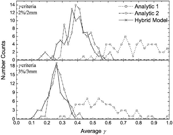
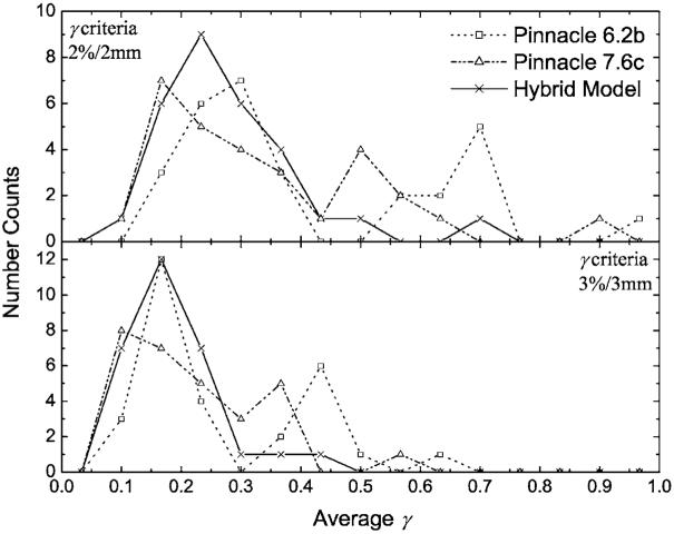
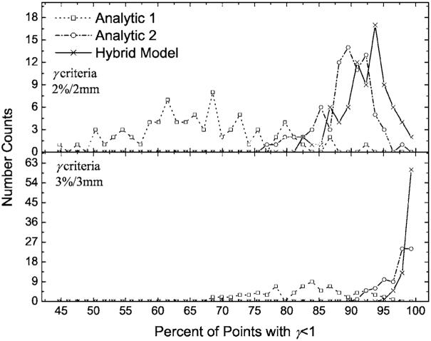
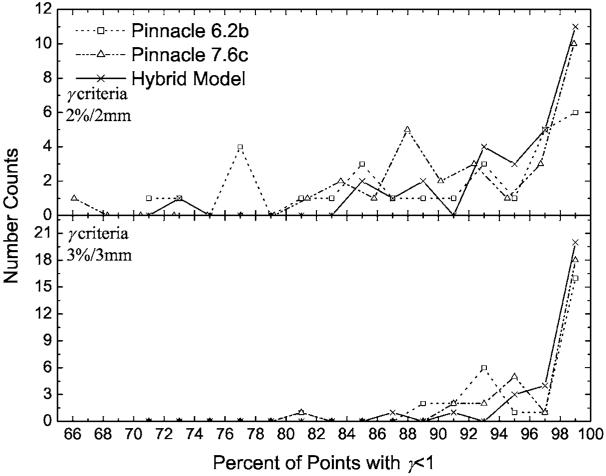
The overall accuracy of the hybrid, Analytic 1, and Analytic 2 methods, as well as the PINNACLE3 algorithms were evaluated by performing gamma analysis. The per-field results were binned for each field type. DMLC results are presented in Fig. 6 and 7 for the SMLC cases. Similarly, the histogram data for fractions of points with γ ≤1 are plotted for the DMLC fields in Fig. 8 and for the SMLC fields in Fig. 9. With an increase in the complexity of the MLC models, from Analytic 1 to the hybrid method, the agreement between calculations and measurements, in terms of fraction of points with γ ≤1 and , improves.
Fig. 6.
The number of dynamic multileaf collimator (DMLC) fields with an observed for Analytic 1, Analytic 2, and the hybrid methods. Data were binned into 0.025 intervals for plotting purposes. The top panel is for gamma acceptance criteria of 2% /2 mm, while the bottom panel is for acceptance criteria of 3% /3 mm. With an increase in the rigor of the MLC modeling by the analytic methods, the difference between the analytic and Monte Carlo modeling of the MLC decreases.
Fig. 7.
The number of segmented multileaf collimator (SMLC) fields with an observed for PINNACLE3 v6.2b, PINNACLE3 v7.6c, and the hybrid methods. Data were binned into 0.067 intervals for plotting purposes. PINNACLE3 v7.6c performs better than PINNACLE3 v6.2b, however, they hybrid method best reproduces the film measurements.
Fig. 8.
The number of dynamic multileaf collimator (DMLC) fields with γ ≤1 for the same fields as in Fig. 6. Data were binned into 1.4% intervals for plotting purposes. As in Fig. 6 with an increase in the sophistication of the analytic MLC modeling methods, a greater fraction of the points (for each field) have γ ≤1.
Fig. 9.
The number of segmented multileaf collimator (SMLC) fields with γ ≤1 for the same fields as in Fig. 7. Data were binned into 2% intervals for plotting purposes. PINNACLE3 v7.6c computed doses have more points per image with γ ≤1, than PINNACLE3 6.2b computed doses. However, the hybrid method demonstrates closer agreement with measurements than either PINNACLE3 implementation.
The average of the values (with their corresponding standard deviations) was evaluated [cf. Eq. (5)] over all fields for each of the calculation methods. Similarly, the average of the fraction of the points with γ ≤1 for each calculation and delivery (DMLC or SMLC) method was calculated along with its associated standard deviation. These results are summarized in Table III and Figs. 6 and 8. The results indicate that as the gamma tolerance changes from 3% /3 mm to 2% /2 mm, the deviation between the methods increases. In addition, the incorporation of the tongue-and-groove effect in the DMLC IMRT module of PINNACLE3 v7.6c improved the gamma results (not presented in graphical form) with respect to the Analytic 2 method. For the common clinical criteria of 3% /3 mm, 76 (out of 79) fields have more than 95% of the points with γ ≤1 for PINNACLE3 v7.6c, while for Analytic 2, only 67 (out of 79) pass the same criteria. Moreover, the and the averages of the fractions of points with γ ≤1, for PINNACLE3 v7.6c DMLC, fall in between the corresponding results for the hybrid and the Analytic 2 methods (cf. Table III), demonstrating the incremental improvement attained by incorporating the tongue-and-groove modeling. Similarly, the PINNACLE3 v7.6c results are better than the results obtained with PINNACLE3 v6.2b (cf. Fig. 9 and Table III). The hybrid method showed the lowest and the highest fractional number of points with γ ≤1 over all five methods in both DMLC and SMLC IMRT fields. For all 79 DMLC fields, the hybrid method had more than 95% of the points with γ ≤1 for the 3% /3 mm criteria and for the 29 SMLC fields, in all but two cases, more than 95% of the points had γ ≤1. For the more restrictive 2% /2 mm criteria, greater improvements in the and the average fraction of the points with γ ≤1 were observed with the hybrid method than for the 3% /3 mm criteria. For both criteria, the hybrid method results are superior to all analytic method results.
Table III.
Averages of the average γ values and averages of the fraction of points with γ<1 with 2% /2 mm and 3% /3 mm criteria for the 79 dynamic multileaf collimator (DMLC) and 29 segmented multileaf collimator (SMLC) intensity modulated radiation therapy (IMRT) fields. The one-standard deviation for each quantity is given in parenthesis. For each IMRT type, one-way paired ANOVA tests indicated that the improved gamma results for the hybrid method is statistically significant.
| 2% /2 mm |
3% /3 mm |
||||
|---|---|---|---|---|---|
| IMRT type | Method | % pass γ<1 | % pass γ<1 | ||
| DMLC | Hybrid | 0.38 (±0.08) | 92.2 (±3.7) | 0.25 (±0.05) | 99.0 (±0.9) |
| DMLC | PINNACLE3 7.6c | 0.4 (±0.1) | 90.0 (±4.3) | 0.27 (±0.08) | 98.2 (±2.3) |
| DMLC | Analytic 2 | 0.41 (±0.08) | 89.0 (±4.2) | 0.28 (±0.05) | 97.0 (±2.2) |
| DMLC | Analytic 1 | 0.85 (±0.2) | 66.1 (±9.7) | 0.56 (±0.14) | 83.0 (±7.1) |
| SMLC | Hybrid | 0.27 (±0.1) | 94.5 (±6.1) | 0.19 (±0.08) | 98.3 (±2.8) |
| SMLC | PINNACLE3 7.6c | 0.34 (±0.2) | 92.2 (±7.7) | 0.22 (±0.12) | 97.1 (±4.3) |
| SMLC | PINNACLE3 6.2b | 0.41 (±0.22) | 89.2 (±9.5) | 0.27 (±0.14) | 96.0 (±4.9) |
A statistical significance of the improved averages, listed in Table III, was established by performing paired one-way ANOVA tests between the hybrid and each analytic method results. In each case, the improvement in the hybrid method average value was found to be statistically significant, with typical p-values of <0.001, and a maximum p-value of 0.02 (PINNACLE v7.6c SMLC 3% /3 mm fraction of points with γ ≤1). Thus, it can be concluded that the hybrid method better reproduces measured in-phantom planar dose distributions based on and an average percentage of points with γ ≤1.
IV. DISCUSSION
A hybrid computation method, which uses a detailed MC simulation of the accelerator head (BEAM19) and the MLC,6 and is coupled with an analytic dose computation algorithm to estimate the resultant dose, was presented and evaluated. Detailed testing of the performance of this calculation method with respect to film-based 2D-measured dose distributions and analytic and commercially available methods was performed. The design and the performance of the hybrid method make it especially suitable for accurately calculating doses from DMLC and SMLC IMRT fields with high modulation. Under the conditions investigated, the method showed that at 3% /3 mm gamma acceptance criteria, at least 95% of the points for each DMLC field, and for 27 (out of 29) SMLC fields, had γ ≤1. The method is more accurate than our in-house and commercial, clinically implemented, analytic methods. It is also robust in calculating highly modulated doses, modeling equally well SMLC and DMLC fields. The observed residual differences between the measured and the calculated doses are small and can not be identified as if arising from measurements or calculations. Comparisons of film to film measurements for identical fields, for a few test cases, showed that at 2% /2 mm and 3% /3 mm criteria the fraction of the points with γ ≤1 can be as low as 93% and 97%, respectively. Note, it is expected that residual errors may persist between the hybrid method and a full MC treatment of the MLC and the patient as a result of inherent limitations in the transmission matrix approach, such as neglecting the differential beam hardening12,21 and loss of information regarding the directional dependence of the MLC scattered radiation.
This study demonstrated that the fraction of points with γ ≤1 increases with an increase in the rigor with which the analytic methods model the MLC characteristics. Furthermore, the presented results revealed that the proposed hybrid method has the best accuracy, which is expected since it directly accounts for field-specific MLC leakage and scattered radiation. The hybrid method places an upper limit on the dosimetric accuracy that can be obtained when intensity modulation is included in dose computations via energy fluence transmission matrices.
In terms of computation time, a benchmark of the hybrid and the analytic methods showed two orders of magnitude difference, that is: 600 versus 5 CPU seconds for a typical DMLC IMRT field, respectively. Note, that the analytic methods which employ more rigorous modeling of the MLC transmission properties (e.g., tongue-and-groove), require additional computation time, thus reducing the time difference. Additionally, as implemented in this report, the majority of time with the hybrid model is spent transporting particles through the accelerator head using the user code BEAM.19 This time-consuming portion of the calculation could easily be replaced with a multiple source model.31 Numerical experiments on a few test cases, using a multiple source model,31 indicated that the hybrid method computation time may be reduced by five to ten times (depending on the field size) without compromising the accuracy of the resultant transmission matrices.
While the clinical significance of the improvement in fluence-to-trajectory converters, such as the hybrid method presented here, can not be determined from in-phantom studies, their potential significance can be inferred in part from previous comparisons between full MC and full analytic dose computations. A comparative study32 between full MC dose calculations (MC used for both fluence estimation and patient calculation) and dose calculations performed with the Analytic 1 method coupled with PINNACLE3 v6.2b SC algorithm, demonstrated that 5% dose deviations were common. Although the source of the differences was not conclusively identified, a major contributor to the observed discrepancies was likely the incident photon energy fluence estimation. If either, Analytic 2, PINNACLE3 7.6, or the hybrid method were used, discrepancies with respect to full MC simulations would be expected to be reduced. However, a detailed analysis of the relative importance of the incident energy fluence prediction and patient heterogeneities on dose calculation accuracy for clinical cases is left to a future study.
V. CONCLUSIONS
A dose-calculation method that accurately accounts for intensity modulation caused by dynamic or step-and-shoot IMRT fields, delivered with MLCs, has been developed. Monte Carlo radiation-transport techniques are used to determine the transmission of the energy fluence through the MLC, and a conventional (Superposition/Convolution) dose-computation technique is used to compute dose to a phantom. Comparisons with in-phantom film dose measurements and with analytic fluence estimation methods reveal that the hybrid method better predicts measurements based upon gamma analyses for static and dynamic test cases. By using a Monte Carlo technique to compute the energy fluence modulation, an upper limit on the accuracy, that can be obtained when intensity modulation is included in the dose computation via an energy fluence transmission matrix, is obtained.
ACKNOWLEDGMENTS
This work was supported by Grant No. R01CA98524 from the National Institutes of Health. The authors would like to thank Mrs. Devon Murphy Stein for her meticulous editing of the manuscript.
References
- 1.Galvin JM, Ezzell G, Eisbrauch A, Yu C, Butler B, Xiao Y, Rosen I, Rosenman J, Sharpe M, Xing L, Xia P, Lomax T, Low DA, Palta J. Implementing IMRT in clinical practice: a joint document of the American Society for Therapeutic Radiology and Oncology and the American Association of Physicists in Medicine. Int. J. Radiat. Oncol., Biol., Phys. 2004;58(5):1616–34. doi: 10.1016/j.ijrobp.2003.12.008. [DOI] [PubMed] [Google Scholar]
- 2.Low DA. Quality assurance of intensity-modulated radiotherapy. Semin. Radiat. Oncol. 2002;12(3):219–28. doi: 10.1053/srao.2002.33700. [DOI] [PubMed] [Google Scholar]
- 3.CWG I. Intensity-modulated radiotherapy: current status and issues of interest. Int. J. Radiat. Oncol., Biol., Phys. 2001;51(4):880–914. doi: 10.1016/s0360-3016(01)01749-7. [DOI] [PubMed] [Google Scholar]
- 4.Chen Y, Boyer AL, Ma CM. Calculation of x-ray transmission through a multileaf collimator. Med. Phys. 2000;27(8):1717–26. doi: 10.1118/1.1286555. [DOI] [PubMed] [Google Scholar]
- 5.Chen Y, Hou Q, Galvin JM. A graph-searching method for MLC leaf sequencing under constraints. Med. Phys. 2004;31(6):1504–11. doi: 10.1118/1.1737512. [DOI] [PubMed] [Google Scholar]
- 6.Siebers JV, Keall PJ, Kim JO, Mohan R. A method for photon beam Monte Carlo multileaf collimator particle transport. Phys. Med. Biol. 2002;47(17):3225–49. doi: 10.1088/0031-9155/47/17/312. [DOI] [PubMed] [Google Scholar]
- 7.Spirou SV, Chui CS. Generation of arbitrary intensity profiles by dynamic jaws or multileaf collimators. Med. Phys. 1994;21(7):1031–41. doi: 10.1118/1.597345. [DOI] [PubMed] [Google Scholar]
- 8.Webb S, Bortfeld T, Stein J, Convery D. The effect of stair-step leaf transmission on the ‘tongue-and-groove problem’ in dynamic radiotherapy with a multileaf collimator. Phys. Med. Biol. 1997;42(3):595–602. doi: 10.1088/0031-9155/42/3/011. [DOI] [PubMed] [Google Scholar]
- 9.Yu CX, Symons MJ, Du MN, Martinez AA, Wong JW. A method for implementing dynamic photon beam intensity modulation using independent jaws and a multileaf collimator. Phys. Med. Biol. 1995;40(5):769–87. doi: 10.1088/0031-9155/40/5/005. [DOI] [PubMed] [Google Scholar]
- 10.Belec J, Patrocinio H, Verhaegen F. Development of a Monte Carlo model for the Brainlab microMLC. Phys. Med. Biol. 2005;50(5):787–99. doi: 10.1088/0031-9155/50/5/005. [DOI] [PubMed] [Google Scholar]
- 11.Dirkx ML, Heijmen BJ, van Santvoort JP. Leaf trajectory calculation for dynamic multileaf collimation to realize optimized fluence profiles. Phys. Med. Biol. 1998;43(5):1171–84. doi: 10.1088/0031-9155/43/5/009. [DOI] [PubMed] [Google Scholar]
- 12.Fix MK, Manser P, Born EJ, Mini R, Ruegsegger P. Monte Carlo simulation of a dynamic MLC based on a multiple source model. Phys. Med. Biol. 2001;46(12):3241–57. doi: 10.1088/0031-9155/46/12/312. [DOI] [PubMed] [Google Scholar]
- 13.Liu HH, Verhaegen F, Dong L. A method of simulating dynamic multileaf collimators using Monte Carlo techniques for intensity-modulated radiation therapy. Phys. Med. Biol. 2001;46(9):2283–98. doi: 10.1088/0031-9155/46/9/302. [DOI] [PubMed] [Google Scholar]
- 14.Deng J, Pawlicki T, Chen Y, Li J, Jiang SB, Ma CM. The MLC tongue-and-groove effect on IMRT dose distributions. Phys. Med. Biol. 2001;46(4):1039–60. doi: 10.1088/0031-9155/46/4/310. [DOI] [PubMed] [Google Scholar]
- 15.van Santvoort JP, Heijmen BJ. Dynamic multileaf collimation without ‘tongue-and-groove’ underdosage effects. Phys. Med. Biol. 1996;41(10):2091–105. doi: 10.1088/0031-9155/41/10/017. [DOI] [PubMed] [Google Scholar]
- 16.Aaronson RF, DeMarco JJ, Chetty IJ, Solberg TD. A Monte Carlo based phase space model for quality assurance of intensity modulated radiotherapy incorporating leaf specific characteristics. Med. Phys. 2002;29(12):2952–8. doi: 10.1118/1.1523409. [DOI] [PubMed] [Google Scholar]
- 17.Mohan R, Arnfield M, Tong S, Wu Q, Siebers J. The impact of fluctuations in intensity patterns on the number of monitor units and the quality and accuracy of intensity modulated radiotherapy. Med. Phys. 2000;27(6):1226–37. doi: 10.1118/1.599000. [DOI] [PubMed] [Google Scholar]
- 18.Nelson WR, Hirayama H, Rogers DWO. SLAC-265, Stanford Linear Accelerator Center. 1985. The EGS4 Code System. [Google Scholar]
- 19.Rogers DW, Faddegon BA, Ding GX, Ma CM, We J, Mackie TR. BEAM: a Monte Carlo code to simulate radiotherapy treatment units. Med. Phys. 1995;22(5):503–24. doi: 10.1118/1.597552. [DOI] [PubMed] [Google Scholar]
- 20.Briesmeister JF. LA-13181, Los Alamos National Laboratory. 1997. MCNP—A General Monte Carlo N-Particle Transport Code, Version 4B. [Google Scholar]
- 21.Kim JO, Siebers JV, Keall PJ, Arnfield MR, Mohan R. AMonte Carlo study of radiation transport through multileaf collimators. Med. Phys. 2001;28(12):2497–506. doi: 10.1118/1.1420734. [DOI] [PubMed] [Google Scholar]
- 22.Wu Q, Mohan R. Algorithms and functionality of an intensity modulated radiotherapy optimization system. Med. Phys. 2000;27(4):701–11. doi: 10.1118/1.598932. [DOI] [PubMed] [Google Scholar]
- 23.Wu Q, Mohan R, Morris M, Lauve A, Schmidt-Ullrich R. Simultaneous integrated boost intensity-modulated radiotherapy for locally advanced head-and-neck squamous cell carcinomas. I: dosimetric results. Int. J. Radiat. Oncol., Biol., Phys. 2003;56(2):573–85. doi: 10.1016/s0360-3016(02)04617-5. [DOI] [PubMed] [Google Scholar]
- 24.Philips . Philips Pinnacle Manual Release 7.4. 2004. Pinnacle Physics Instructions for Use; pp. 4-15–4-22. [Google Scholar]
- 25.Van Dyk J, Barnett RB, Cygler JE, Shragge PC. Commissioning and quality assurance of treatment planning computers. Int. J. Radiat. Oncol., Biol., Phys. 1993;26(2):261–73. doi: 10.1016/0360-3016(93)90206-b. [DOI] [PubMed] [Google Scholar]
- 26.Low DA, Harms WB, Mutic S, Purdy JA. A technique for the quantitative evaluation of dose distributions. Med. Phys. 1998;25(5):656–61. doi: 10.1118/1.598248. [DOI] [PubMed] [Google Scholar]
- 27.Harms WB, Sr., Low DA, Wong JW, Purdy JA. A software tool for the quantitative evaluation of 3D dose calculation algorithms. Med. Phys. 1998;25(10):1830–6. doi: 10.1118/1.598363. [DOI] [PubMed] [Google Scholar]
- 28.Arnfield MR, Siebers JV, Kim JO, Wu Q, Keall PJ, Mohan R. A method for determining multileaf collimator transmission and scatter for dynamic intensity modulated radiotherapy. Med. Phys. 2000;27(10):2231–41. doi: 10.1118/1.1312190. [DOI] [PubMed] [Google Scholar]
- 29.LoSasso T, Chui CS, Ling CC. Physical and dosimetric aspects of a multileaf collimation system used in the dynamic mode for implementing intensity modulated radiotherapy. Med. Phys. 1998;25(10):1919–27. doi: 10.1118/1.598381. [DOI] [PubMed] [Google Scholar]
- 30.Wu Q, Arnfield M, Tong S, Wu Y, Mohan R. Dynamic splitting of large intensity-modulated fields. Phys. Med. Biol. 2000;45(7):1731–40. doi: 10.1088/0031-9155/45/7/302. [DOI] [PubMed] [Google Scholar]
- 31.Fix MK, Keall PJ, Dawson K, Siebers JV. Monte Carlo source model for photon beam radiotherapy: photon source characteristics. Med. Phys. 2004;31(11):3106–21. doi: 10.1118/1.1803431. [DOI] [PubMed] [Google Scholar]
- 32.Sakthi N, Keall P, Mihaylov I, Wu Q, Wu Y, Williamson J, Schmidt-Ulrich R, Siebers J. Monte Carlo-based dosimetry of head- and-neck patients treated with SIB-IMRT. Int. J. Radiat. Oncol., Biol., Phys. 2006;64(3):968–77. doi: 10.1016/j.ijrobp.2005.09.049. [DOI] [PubMed] [Google Scholar]


