Abstract
The goal of metabolomics analyses is the detection and quantitation of as many sample components as reasonably possible in order to identify compounds or “features” that can be used to characterize the samples under study. When utilizing electrospray ionization to produce ions for analysis by mass spectrometry (MS), it is important that metabolome sample constituents be efficiently separated prior to ion production, in order to minimize ionization suppression and thereby extend the dynamic range of the measurement, as well as the coverage of the metabolome. Similarly, optimization of the MS inlet and interface can lead to increased measurement sensitivity. This perspective review will focus on the role of high resolution liquid chromatography (LC) separations in conjunction with improved ion production and transmission for LC-MS-based metabolomics. Additional emphasis will be placed on the compromise between metabolome coverage and sample analysis throughput.
Keywords: liquid chromatography, electrospray ionization, ion mobility spectroscopy, mass spectrometry, metabolomics
Introduction
The majority of early metabolomics studies utilized nuclear magnetic resonance (NMR) spectroscopy- [1, 2] and gas chromatography (GC)-based approaches [3, 4]. However, investigators have also applied high performance liquid chromatography (HPLC) coupled with UV detection [5], pyrolysis-mass spectrometry (MS) [6], and inductively-coupled plasma (ICP) atomic emission and ICP-MS [7] among other techniques. Current metabolomics studies rely almost exclusively on 1H NMR, GC-MS and LC-MS due to the technological maturity of the instrumentation and the recent independent advancements made in all three fields. This perspective review will highlight the application of high-efficiency (peak capacity ∼103) LC interfaced with MS via electrospray ionization (ESI), focusing on increased production and delivery of analyte ions to the detector.
High-Resolution LC and Nanoflow Separations
The goal of metabolomics experiments is the detection and quantitation of as many sample components as reasonably possible in order to determine or identify “features” (characterized by m/z and retention time) that can be used to describe a disease, growth condition, or other external perturbation. Inherent to this approach is the high sample complexity of metabolite extracts when employing global extraction protocols. One of the disadvantages to utilizing ESI for interfacing LC to MS in metabolic profiling and metabolomics studies is the occurrence of ionization suppression [8] during co-elution of two or more compounds with dramatic differences in proton affinities or surface activities, particularly if high analyte concentrations are present [9-12]. This can produce signal intensities that are not linearly related to the analyte concentrations or lead to the inability to detect analytes. Other contributing factors include solvent matrix effects (i.e., where solvent components “compete” with analytes for ionization) and erratic electrospray behavior as a result of increased liquid conductivity from various salts and charged species [8]. The effect of ionization suppression on analyte molecules can be greatly minimized through improved front-end LC separations and reduced LC operating flow rates (both of which lead to more efficient ESI), as well as decreased sample loading to the LC column. Thus, the front-end separation efficiency, quantified by the separation peak capacity (i.e., the theoretical number of resolved peaks that can be fit into the separation space [13]), determines the coverage and completeness of analysis. Increased LC peak capacities allow highly complex samples to be better characterized through reduction of co-eluting species and increased eluent concentration, potentially reducing ionization suppression and resulting in an overall increase in the dynamic range of the measurement. This increase is generally due to improved detection of lower abundance species, which are ultimately better resolved from species that are present either in higher abundance or that have higher proton affinities or surface activities.
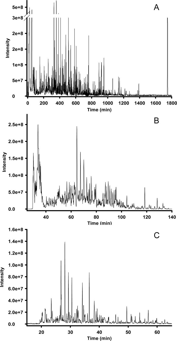
As has been reported for LC-MS analyses of proteolytically digested proteins, separation peak capacities on the order of 102 are typically viewed as moderate-efficiency, 103 as high-efficiency, and 104 as ultra-high-efficiency [14, 15]. Reversed-phase LC is the only 1D format to date that has been reported to achieve high-efficiency separations of global metabolite extracts: Shen et al. [16] recently reported LC peak capacities of ∼1500 in microbial metabolome analyses utilizing reversed-phase capillary LC coupled with Fourier transform ion cyclotron resonance (FTICR) MS, and Plumb and colleagues [17] described LC peak capacities of ∼1000 in a 1 h analysis of the rat urine metabolome using ultra-performance liquid chromatography (UPLC) in conjunction with elevated temperatures and high linear mobile phase velocities. Both of these studies utilized small-particle (≤ 3 μm) packed columns, which required operating pressures in excess of 10,000 psi to maintain the optimum mobile phase linear velocity across the column. The use of small diameter packing materials provides increased LC separation efficiency through a decrease in the height equivalent to a theoretical plate, resulting in an increase in the number of theoretical plates per column [18]. Alternatively, silica- and polymer-based reversed-phase monolithic capillary columns have been utilized in metabolomics applications [19, 20], providing 105 theoretical plates at a modest pressure drop in separations of standard compounds [21]. The effect of peak capacity on the number of metabolite features detected during LC-MS analyses is demonstrated in Figure 1, which shows three chromatograms with differing peak capacities from reversed-phase capillary LC-FTICR MS analysis of the same metabolite extract. The separation shown in Figure 1A produced a peak capacity of ∼1500 over 30 h at a flow rate of ∼70 nL/min and resulted in the detection of ∼5000 features after downstream data processing. Decreasing the separation efficiency to peak capacities of ∼500 (Figure 1B) and ∼350 (Figure 1C) at similar flow rates resulted in significant concomitant decreases in the number of detected features for the same sample, with ∼2000 and 450 features identified, respectively, after downstream data processing. It is apparent that, as the separation efficiency decreases, the ion intensity for the detected features becomes less uniform due to decreased chromatographic resolution and, to some uncertain extent, increased ionization suppression of co-eluting species; several high-abundance species begin to dominate the chromatograms in Figures 1B and 1C, while low-abundance species begin to recede to the baseline. While it is desirable to routinely achieve separation peak capacities of ∼103, the characteristic longer analysis times are not amenable to high-throughput metabolomics experiments where tens to hundreds of samples might be available or necessary for study. To increase the throughput of high-efficiency LC separations for metabolomic applications, multi-column systems have been developed [22]. Alternatively, Plumb et al. [17] have addressed this issue through the use of UPLC and high column temperatures, achieving high-efficiency separations in 1 h and moderate- to high-efficiency separations (peak capacity of ∼700) in as little as 10 min. However, the relatively high flow rates (0.8 mL/min) may minimize the utility of this approach for sensitive ESI-MS measurements, particularly in sample-limited situations.
Figure 1. Analysis of the Shewanella oneidensis metabolome utilizing reversed-phase capillary LC coupled with FTICR MS.
High-resolution capillary LC separation of the S. oneidensis metabolome was performed using an 11 Tesla FTICR as the mass detector. The operating pressure of the LC was 20,000 psi and the reversed-phase C18 capillary columns are as follows: (A) 50 μm i.d. × 2 m, 3 μm dP, (B) 50 μm i.d. × 50 cm, 2 μm dP, (C) 50 μm i.d. × 20 cm, 1.4 μm dP. Peak-capacities of ∼1500, ∼500, and ∼350 were calculated for the separations shown in A, B, and C, respectively. Adapted from reference 28: Biomarkers Med., 1, T. Metz, Q. Zhang, J. Page, Y. Shen, S. Callister, J. Jacobs, and R. Smith, Future of liquid chromatography-mass spectrometry in metabolic profiling and metabolomic studies for biomarker discovery, 159−185, 2007, with permission from Future Medicine.
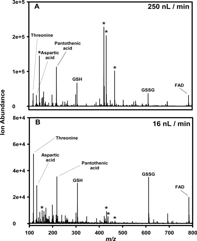
While high-efficiency front-end separations minimize ionization suppression and increase coverage of the detectable metabolome by LC-MS-based methods, of equal importance is the use of low LC flow rates in order to increase ionization efficiency (defined as the number of analyte ions created divided by the number of analyte molecules delivered to the ESI emitter) and, therefore, the overall sensitivity of the measurement [10, 23, 24]. Lower LC flow rates create smaller charged droplets during ESI, and, consequently, the smaller droplets enable more efficient solvent evaporation [25, 26], while also increasing the number of available charges per analyte [26] and reducing matrix suppression effects [10, 11]. Typical capillary LC separations utilize columns with inner diameters of 150−360 μm and operating flow rates of 1−10 μL/min. The electrospray source coupled with such front-end separations typically leads to droplets with an initial diameter of ≥1 μm, and Wilm and Mann have calculated that such droplets contain more than 150,000 analyte molecules for analyte concentrations of 0.5 μM [25]. The relatively large size of these initial charged droplets are related to the origin of “matrix” and ionization suppression effects and require additional desolvation and fission events to produce gas-phase ions, leading to increased ion losses in the ESI interface and incomplete ion production [27]. In contrast, improved ESI efficiency at very low flow rates (∼20 nL/min [28]) is generally due to a more uniform ion intensity for analytes with different proton affinities or surface activities. This is illustrated in Figure 2, which shows negative-ESI MS spectra acquired for an equimolar mixture of metabolites. At the lower nanoflow rate, more uniform ion intensities are observed for all components of the mixture; in addition, background ions formed from solvent clusters are often greatly diminished in intensity [29]. Thus, the combination of high-resolution LC separations and low flow rates will greatly reduce ionization suppression effects, leading to improved coverage, sensitivity, and quantitation.
Figure 2. Comparison of ion intensities for a metabolite mixture analyzed by two nano-ESI flow rates.
An equimolar mixture (10 μM) of threonine, aspartic acid, pantothenic acid, reduced glutathione (GSH), oxidized glutathione (GSSG), and flavin adenine dinucleotide (FAD) in water:acetonitrile (50:50, v/v) was electrosprayed in negative-ESI mode. (A) flow rate of 250 nL/min, (B) flow rate of 16 nL/min. Ions due to solvent are indicated by *. Reproduced from reference 28: Biomarkers Med., 1, T. Metz, Q. Zhang, J. Page, Y. Shen, S. Callister, J. Jacobs, and R. Smith, Future of liquid chromatography-mass spectrometry in metabolic profiling and metabolomic studies for biomarker discovery, 159−185, 2007, with permission from Future Medicine.
Improved Ion Production and Transmission
Improving the sensitivity for detecting and identifying metabolites can enable new applications. For example, improving measurement sensitivity can lead to high quality characterization of mass limited samples, such as micro-dissected cells, micro-biopsies, or even single cells. The sensitivity of ESI-MS is largely determined by the ionization efficiency and the transmission efficiency (i.e., the ability to transfer the ions from atmospheric pressure to the low-pressure region of the mass analyzer) [30, 31].
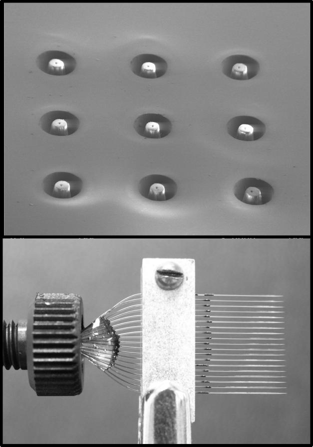
Ionization efficiency is affected by a number of factors, including flow rate, solvent composition, and analyte properties. A straight forward approach to improving ionization efficiency is to reduce the flow rate along with the size of the ES emitter, as discussed above. However, performing LC at flow rates compatible with the nano-ESI regime has been difficult and, for the most part, prevented by the difficulty of packing narrow-bore capillaries (eg., 5 to 30 μm i.d.) with small LC particles [27]. Further, the low tolerance for dead volumes in such small capillaries does not allow the use of conventional valving and sample loading techniques [32]. One method to overcome this limitation is to split the flow post-column such that the majority of eluent is diverted to waste, while greatly reducing the flow rate at the ES emitter [33]; however, a major drawback to this approach is that most of the sample is never analyzed. An alternative is to divide the flow from the LC column among multiple ES emitters, enabling several simultaneous nano-ESs to replace the single higher flow rate ES. This has been demonstrated with microfabricated devices [34, 35] and arrays of chemically etched fused silica tubing [36]. Figure 3 shows two types of these devices created in our laboratory: a laser-machined polycarbonate microfluidic chip (top frame) and an array of chemically etched 10 μm i.d. emitters (bottom frame). These devices have been demonstrated to provide stable multi-electrosprays with increased ES currents, improved quantitation, and ∼10-fold increase in sensitivity [36]. The multi-ES emitters disperse the ion/droplet plume across a larger area, which requires the use of a multi-inlet source to provide effective sampling [36, 37]. Other approaches have improved the ionization efficiency through the addition of energy to the ES droplets with a heated nitrogen background gas or by heating the inlet to increase desolvation and liberate more analyte ions [38-41].
Figure 3. Pictures of two multi-ES emitter devices.
The top frame is an electron micrograph of a nine-ESI nozzle chip laser-machined in polycarbonate. The bottom frame is an array of 19 chemically etched silica capillary emitters.
ESI-MS sensitivity is further limited by very low ion transmission efficiencies, with the largest losses occurring at the inlet and skimmer [28, 31, 42]. Ion loss at the MS inlet is caused mainly by the limited area of the inlet compared to the size of the droplet/ion plume. Large i.d. orifices or capillaries can be used to increase the sampling area; however, increased pumping capacity is also necessary to maintain the vacuum requirements of the instrument [23, 43]. The sampling area can also be increased by using multiple inlets in conjunction with an electrodynamic ion funnel interface [36, 44], providing an additional stage of pumping operated at a relatively higher pressure and requiring only one additional rough pump [37]. Other approaches have focused the ES ion/droplet plume to a smaller area increasing the charge density at the inlet with static DC fields [45-47] or air amplifiers [48, 49] with varying levels of success.
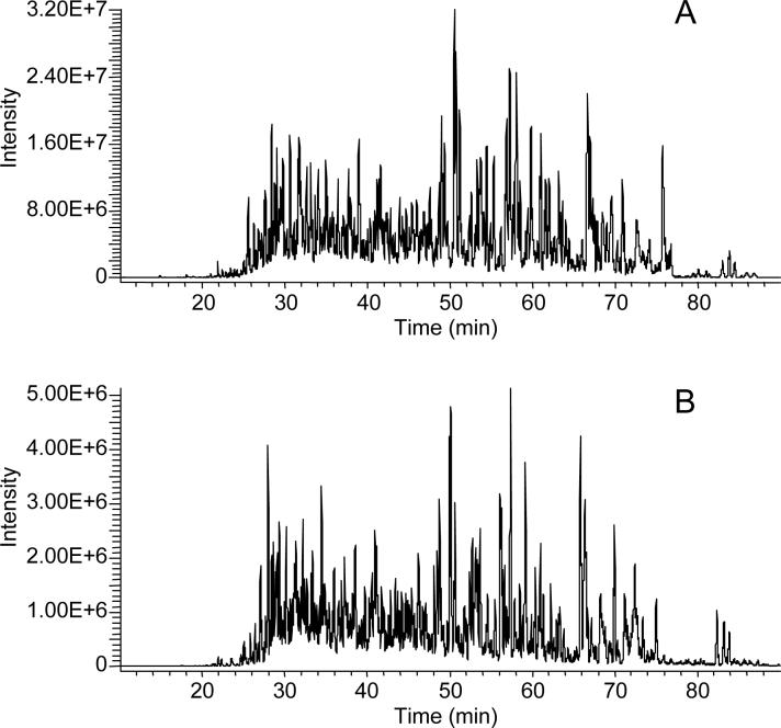
Ion loss at the skimmer in the ESI interface occurs from a mismatch of the size of the ion plume (due to the supersonic expansion of the gas jet exiting the inlet) and the area sampled by the orifice of the skimmer, which is typically ∼1 mm. To reduce ion losses in this region, the electrodynamic ion funnel was developed as an alternative to the skimmer [50-52]. The ion funnel is an adaptation of a stacked ring ion guide [53], where the exit of the ion guide decreases linearly in ring diameter down to the i.d. of the conductance limiting orifice. This allows the entire ion plume from the jet expansion to be sampled and a majority of the buffer gas to be pumped away while the ions are captured, focused, and transmitted. Recently, the ion funnel was adapted and implemented on a linear ion trap MS [54]. That study showed that improving ion transmission efficiency reduced the ion trap injection or “fill” times by ∼90%. Figure 4 shows LC-MS chromatograms from the analysis of a microbial protein digest with (Fig. 4A) and without (Fig. 4B) the ion funnel interface, which provided a ∼7-fold improvement in sensitivity. This improvement was most pronounced at lower sample concentrations, where extended ion accumulation times are required, resulting in a ∼2-fold increase in the number of protein identifications based on downstream analysis of MS/MS spectra. The ion funnel interface was also coupled to a hybrid linear ion trap-FTICR MS and showed a 25 to 50% increase in duty cycle by decreasing the accumulation times needed to reach the larger ion populations required for high resolution mass analyzers [54]. While these initial examples highlight the benefits of the ion funnel in peptide analyses, analogous benefits can be obtained in the analysis of metabolites.
Figure 4. LC-MS chromatograms from the analysis of a microbial protein digest.
A 1 μg sample of S. oneidensis cellular proteins was analyzed by LC-MS on a commercial linear ion trap with (A) and without (B) an electrodynamic ion funnel interface. Adapted from reference 47: Int. J. Mass Spectrom., 265, J. Page, K. Tang, and R. Smith, An electrodynamic ion funnel interface for greater sensitivity and higher throughput with linear ion trap mass spectrometers, 244−250, 2007, with permission from Elsevier.
Separation Power Versus Sample Throughput
High-resolution LC separations performed at nanoflow rates can provide broad coverage of the metabolome, but generally require lengthy analysis times. Metabolomics experiments typically require the analysis of tens to hundreds of technical and biological replicates, particularly for biomarker discovery efforts. For example, analyzing 500 clinical samples using a 100 min LC-MS approach would require at least 34 days to complete. Thus, alternate technologies are needed that can increase the sample analysis throughput, while maintaining high coverage of the metabolome. One such technology is ion mobility spectrometry (also known as plasma chromatography or ion chromatography), which was introduced in the 1970s as a portable ion separation and detection device [55]. Ion mobility spectrometry (IMS) is based on the fact that ions with different shapes travel with different velocities when they are pulled by a weak electric field through a drift cell filled with a buffer gas [56]. In the drift cell, the ion motion quickly reaches a steady state under the action of the forward acceleration force imposed by the electric field and the drag force from the collisions with the buffer gas. As a consequence, the ions drift at a constant velocity proportional to the applied electric field through the proportionality constant, termed mobility. Experimental measurement of ion mobility provides ion structure information, since small compact ions drift more quickly than ions with large extended structures.
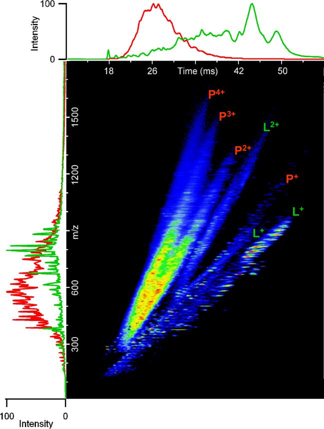
In the late 1990s, IMS was first interfaced with orthogonal time-of-flight (TOF) MS [57, 58], permitting the simultaneous acquisition of ion mobility spectra and mass spectra in a single analysis. Coupling IMS and MS results in an extremely high throughput technique; IMS separations typically require only 10−100 ms, while TOF mass spectra are acquired every ∼30−100 μs. Therefore, several TOF spectra can be acquired for each IMS separation, resulting in high resolution nested spectra of m/z versus drift time for each analysis such that all sample components may be instantly identified, assuming that they have been fully characterized in previous experiments. An additional advantage of IMS-MS is that mass spectral congestion is reduced by the front end IMS separation, increasing the overall peak capacity ∼10−20-fold. It is important to note that this increase is based on the gains observed in our laboratory for IMS-MS separations of peptides. It is likely that the increase in peak capacity for IMS-MS separations of metabolite samples will be greater, due to the greater chemical complexity present in global metabolome extracts relative to protein digests. For example, Figure 5 demonstrates distinct IMS drift times observed for peptides relative to lipids. Similarly, the gas-phase conformations of free amino acids, carbohydrates, nucleotides, and polysaccharides are expected to be distinct and resolved during IMS separations of global metabolome extracts. It is important to note that different charge states of the same peptide display distinct IMS drift times (Figure 5), due to differences in the gas-phase conformation of each peptide species. Interestingly, several doubly charged lipid species were also observed; however, it is not yet known if these represent doubly charged lipids or lipopeptides.
Figure 5. IMS-MS analysis of human plasma proteins and total lipid extract.
IMS-MS separations of a human plasma protein digest and total lipid extract in positive-ESI were performed using a 98-cm IMS drift tube coupled with a TOF MS via an electrodynamic ion funnel. Data from IMS-MS separations of human plasma peptides and lipids were combined and displayed as shown. The m/z profiles for peptides (red) and lipids (green) are shown along the y-axis, while the IMS profiles are shown along the x-axis. Multiply charged species of peptides (P) and lipids or lipopeptides (L) are indicated. (Unpublished data).
A previous hurdle for the broad application of IMS-MS in quantitative studies was its low sensitivity, due to diffusion of ions at the interface between the IMS drift cell and the MS. This problem was effectively solved by incorporating an electrodynamic ion funnel at the IMS-MS interface to refocus ions exiting the drift cell [59]. However, a continuing challenge is low IMS resolving power (Rp) when studying complex mixtures. IMS Rp has traditionally been defined as the median drift time of an ion divided by the width of the IMS peak measured at half-height. Under ideal conditions such as homogenous electric field, homogeneous drift gas, and well defined ion gating and negligible contributions from space charge effects, the major contributions to the measured peak width are ion gate pulse width and diffusion. Recent attempts to attain higher IMS Rp have utilized longer IMS drift cells, higher pressures, and stronger electric fields to reduce diffusion while gaining more separation time [60].
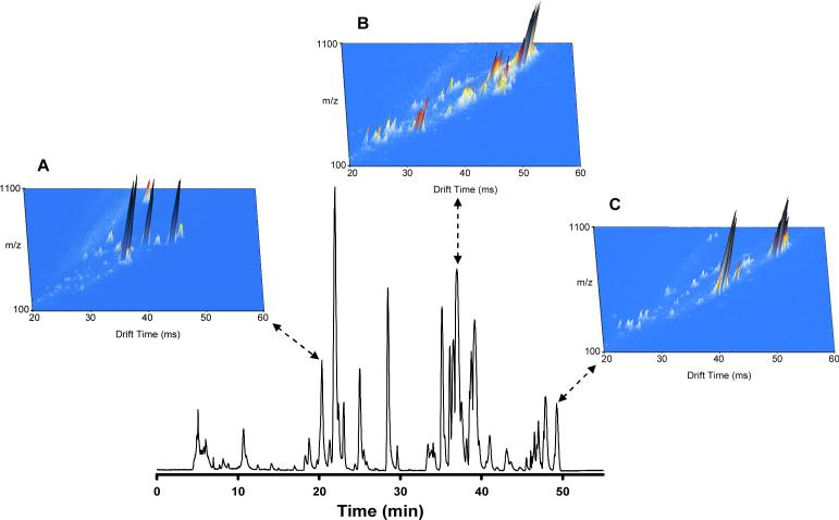
Higher IMS resolving powers have allowed IMS-MS to be utilized in the analysis of isobaric species with minimal structural differences, including polymer subunits [61], cis-trans isomers [60], and diastereomers [62]. However, the highest IMS resolving power achieved to date is ∼200 for singly-charged ions [63, 64], which corresponds to a separation peak capacity of ∼100, depending on IMS peak widths and sample complexity. Such peak capacities are generally insufficient to separate all the components in complex samples. To increase the peak capacity of IMS-MS separations, a third dimension LC stage can be added. Complex sample mixtures have already been effectively separated in both LC and IMS stages prior to introduction to the MS [65, 66]. Figure 6 demonstrates the increased separation capability obtained when LC and IMS are coupled prior to the MS stage. IMS-MS spectra were summed across 10 s in three LC regions, corresponding to the elution of lysophospholipids (Fig. 6A), phospholipids (Fig. 6B), and triacylglycerides (Fig. 6C). What initially appeared as single LC peaks corresponding to only a few co-eluting species are now revealed to contain complex mixtures of species with varying levels of abundance. Of particular interest was the separation of three isobaric species (Figure 7), which likely correspond to isomers of the same phospholipid. Therefore, applications of LC-IMS-MS in metabolomics studies will likely lead to the identification of previously undetected species in experiments utilizing LC-MS alone. A 20 min moderate-efficiency (peak capacity of 102) LC separation coupled with IMS-MS for a combined LC-IMS-MS peak capacity of ∼104 now enables the analysis of 500 clinical samples in ∼7 days. The increase in peak capacity compared to a one-dimensional LC or IMS separation is due to the orthogonal nature of LC relative to IMS; thus, the individual peak capacities are multiplicative. Similarly, LC may be coupled with high-field asymmetric waveform ion mobility spectrometry (FAIMS)-MS [67], providing analogous high resolution separations at increased throughput. Recently, FAIMS-IMS-MS has been employed in the analysis of tryptic peptides from a mixture of 11 proteins, generating peak capacities of approximately 500 (moderate-efficiency) for the front-end gas-phase separation [68]. Such hybrid separation approaches may become routine in the near future, as laboratories attempt to balance metabolome coverage with sample analysis throughput. An alternative method for increasing sample throughput while maintaining coverage may one day include arrays of LC columns [69, 70] and mass spectrometers [71, 72], with each individual LC-MS unit devoted to the analysis of a particular class of metabolite or fraction of sample in both positive and negative ESI.
Figure 6. LC-IMS-MS analysis of a human total lipid extract.
A human plasma total lipid extract was analyzed by LC-IMS-MS utilizing a 50-min LC separation and a 98-cm IMS drift tube. To indicate the increased separation capability obtained with the combination of LC and IMS, IMS-MS spectra were summed across three 10-s regions (20.83−21.00 min; 37.00−37.17 min; and 49.17−49.33 min) of the LC separation, creating three-dimensional plots of m/z, drift time, and intensity. (Unpublished data).
Figure 7. IMS separation of isobaric lipid species.
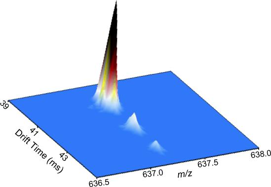
A human plasma total lipid extract was analyzed by LC-IMS-MS utilizing a 50-min LC separation and a 98-cm IMS drift tube. IMS-MS spectra were summed across a 10-s region (corresponding to Figure 6B) of the LC separation, creating a three-dimensional plot of m/z, drift time, and intensity. Three isobaric (m/z 637.2) lipid species were resolved via IMS. (Unpublished data).
Summary
Advancements in front end LC separations and in both electrospray ionization and ion transmission efficiency are enabling increasingly sensitive LC-MS-based metabolomics measurements. Extended and more reproducible coverage of the metabolome is being achieved, resulting in the detection of larger numbers of features characterized by accurately measured masses and retention times. The lower flow rates achieved with small i.d. columns provide improved ionization efficiency, and therefore higher sensitivity and better quantitation. However, the longer columns used to provide high separation peak capacities result in lengthy analysis times, which are not amenable in analyses of the large numbers of samples often required for statistically significant metabolomics studies. Alternative and complementary approaches such as IMS-MS or LC-IMS-MS are being developed that can provide higher throughput or improved peak capacities, enabling the analysis of several hundred samples in a few days with moderate to high coverage.
Acknowledgements
The authors thank the Pacific Northwest National Laboratory (PNNL) Laboratory Directed Research and Development Program for supporting portions of the work shown. Additional support was provided by the NIH (CA126191, DK071283, RR018522) and the SAIC-Frederick (25XS118). Work was performed in the Environmental Molecular Sciences Laboratory, a national scientific user facility located at the PNNL and sponsored by the U.S. Department of Energy Office of Biological and Environmental Research program. PNNL is operated by Battelle for the DOE under Contract No. DE-AC06-76RLO-1830.
References
- 1.Bales J, Higham D, Howe I, Nicholson J, Sadler P. Clin. Chem. 1984;30:426. [PubMed] [Google Scholar]
- 2.Robertson D, Reily M, Sigler R, Wells D, Paterson D, Braden T. Toxicol. Sci. 2000;57:326. doi: 10.1093/toxsci/57.2.326. [DOI] [PubMed] [Google Scholar]
- 3.Rosenberg R, Robinson A, Partridge D. Clin. Biochem. 1975;8:365. doi: 10.1016/s0009-9120(75)93752-2. [DOI] [PubMed] [Google Scholar]
- 4.McConnell M, Novotny M. J. Chromatogr. 1975;112:559. doi: 10.1016/s0021-9673(00)99985-0. [DOI] [PubMed] [Google Scholar]
- 5.Ramos L. J. Chromatogr. Sci. 1994;32:219. doi: 10.1093/chromsci/32.6.219. [DOI] [PubMed] [Google Scholar]
- 6.Freeman R, Goodacre R, Sisson P, Magee J, Ward A, Lightfoot N. J. Med. Microbiol. 1994;40:170. doi: 10.1099/00222615-40-3-170. [DOI] [PubMed] [Google Scholar]
- 7.Moreda-Pineiro A, Marcos A, Fisher A, Hill S. J. Environ. Monit. 2001;3:352. doi: 10.1039/b103658k. [DOI] [PubMed] [Google Scholar]
- 8.Beaudry F, Vachon P. Biomed. Chromatogr. 2006;20:200. doi: 10.1002/bmc.553. [DOI] [PubMed] [Google Scholar]
- 9.Tang K, Smith R. J. Am. Soc. Mass Spectrom. 2001;12:343. doi: 10.1016/S1044-0305(01)00222-7. [DOI] [PubMed] [Google Scholar]
- 10.Schmidt A, Karas M, Dülcks T. J. Am. Soc. Mass Spectrom. 2003;14:492. doi: 10.1016/S1044-0305(03)00128-4. [DOI] [PubMed] [Google Scholar]
- 11.Tang K, Page J, Smith R. J. Am. Soc. Mass Spectrom. 2004;15:1416. doi: 10.1016/j.jasms.2004.04.034. [DOI] [PMC free article] [PubMed] [Google Scholar]
- 12.Cech N, Enke C. Anal. Chem. 2000;72:2717. doi: 10.1021/ac9914869. [DOI] [PubMed] [Google Scholar]
- 13.Giddings J. Unified Separation Science. John Wiley & Sons, Inc.; New York: 1991. [Google Scholar]
- 14.Shen Y, Zhao R, Berger S, Anderson G, Rodriguez N, Smith R. Anal. Chem. 2002;74:4235. doi: 10.1021/ac0202280. [DOI] [PubMed] [Google Scholar]
- 15.Shen Y, Jacobs J, Camp D, II, Fang R, Moore R, Smith R, Xiao W, Davis R, Tompkins R. Anal. Chem. 2004;76:1134. doi: 10.1021/ac034869m. [DOI] [PubMed] [Google Scholar]
- 16.Shen Y, Zhang R, Moore R, Kim J, Metz T, Hixson K, Zhao R, Livesay E, Udseth H, Smith R. Anal. Chem. 2005;77:3090. doi: 10.1021/ac0483062. [DOI] [PubMed] [Google Scholar]
- 17.Plumb R, Rainville P, Smith B, Johnson K, Castro-Perez J, Wilson I, Nicholson J. Anal. Chem. 2006;78:7278. doi: 10.1021/ac060935j. [DOI] [PubMed] [Google Scholar]
- 18.van Deemter J, Zuiderweg F, Klinkenberg A. Chem. Eng. Sci. 1956;5:271. [Google Scholar]
- 19.Tolstikov V, Lommen A, Nakanishi K, Tanaka N, Fiehn O. Anal. Chem. 2003;75:6737. doi: 10.1021/ac034716z. [DOI] [PubMed] [Google Scholar]
- 20.Tolstikov V, Fiehn O, Tanaka N. Methods Mol. Biol. 2007;358:141. doi: 10.1007/978-1-59745-244-1_9. [DOI] [PubMed] [Google Scholar]
- 21.Hosoya K, Hira N, Yamamoto K, Nishimura M, Tanaka N. Anal. Chem. 2006;78:5729. doi: 10.1021/ac0605391. [DOI] [PubMed] [Google Scholar]
- 22.Ding J, Sorensen C, Zhang Q, Jiang H, Jaitly N, Livesay E, Shen Y, Smith R, Metz T. Anal. Chem. 2007;79:6081. doi: 10.1021/ac070080q. [DOI] [PubMed] [Google Scholar]
- 23.Bruins A. Mass Spectrom. Rev. 1991;10:53. [Google Scholar]
- 24.Abian J, Oosterkamp A, Gelpf E. J. Mass Spectrom. 1999;34 doi: 10.1002/(SICI)1096-9888(1998100)33:10<976::AID-JMS710>3.0.CO;2-7. [DOI] [PubMed] [Google Scholar]
- 25.Wilm M, Mann M. Int. J. Mass Spectrom. Ion Processes. 1994;136:167. [Google Scholar]
- 26.Fernández de la Mora J, Loscertales I. J. Fluid Mech. 1994;260:155. [Google Scholar]
- 27.Smith R, Shen Y, Tang K. Acc. Chem. Res. 2004;37:269. doi: 10.1021/ar0301330. [DOI] [PubMed] [Google Scholar]
- 28.Wilm M, Mann M. Anal. Chem. 1996;68:1. doi: 10.1021/ac9509519. [DOI] [PubMed] [Google Scholar]
- 29.Metz T, Zhang Q, Page J, Shen Y, Callister S, Jacobs J, Smith R. Biomarkers Med. 2007;1:159. doi: 10.2217/17520363.1.1.159. [DOI] [PMC free article] [PubMed] [Google Scholar]
- 30.Cole R. J. Mass Spectrom. 2000;35:763. doi: 10.1002/1096-9888(200007)35:7<763::AID-JMS16>3.0.CO;2-#. [DOI] [PubMed] [Google Scholar]
- 31.Cech N, Enke C. Mass Spectrom. Rev. 2001;20:362. doi: 10.1002/mas.10008. [DOI] [PubMed] [Google Scholar]
- 32.Shen Y, Tolic N, Masselon C, Pasa-Tolic L, Camp D, II, Lipton M, Anderson G, Smith R. Anal. Bioanal. Chem. 2004;378:1037. doi: 10.1007/s00216-003-2329-8. [DOI] [PubMed] [Google Scholar]
- 33.Andrews C, Yu C, Yang E, Vouros P. J. Chromatogr. A. 2004;1053:151. [PubMed] [Google Scholar]
- 34.Tang K, Lin Y, Matson D, Kim T, Smith R. Anal. Chem. 2001;73:1658. doi: 10.1021/ac001191r. [DOI] [PubMed] [Google Scholar]
- 35.Kim W, Guo M, Yang P, Wang D. Anal. Chem. 2007;79:3703. doi: 10.1021/ac070010j. [DOI] [PubMed] [Google Scholar]
- 36.Kelly R, Page J, Tang K, Smith R. Anal. Chem. 2007;79:4192. doi: 10.1021/ac062417e. [DOI] [PubMed] [Google Scholar]
- 37.Ibrahim Y, Tang K, Tolmachev A, Shvartsburg A, Smith R. J. Am. Soc. Mass Spectrom. 2006;17:1299. doi: 10.1016/j.jasms.2006.06.005. [DOI] [PMC free article] [PubMed] [Google Scholar]
- 38.Electrospray Ionization Mass Spectrometry: Fundamentals, Instrumentation, and Applications. John Wiley & Sons, Inc.; New York: 1997. [Google Scholar]
- 39.Chowdhury S, Katta V, Chait B. Rapid Commun. Mass Spectrom. 1990;4:81. doi: 10.1002/rcm.1290040305. [DOI] [PubMed] [Google Scholar]
- 40.Li L, Campbell D, Bennett P, Henion J. Anal. Chem. 1996;68:3397. doi: 10.1021/ac960375w. [DOI] [PubMed] [Google Scholar]
- 41.Allanson J, Biddlecombe R, Jones A, Pleasance S. Rapid Commun. Mass Spectrom. 1996;10:811. [Google Scholar]
- 42.Page J, Kelly R, Tang K, Smith R. J. Am. Soc. Mass Spectrom. 2007 doi: 10.1016/j.jasms.2007.05.018. In Press. [DOI] [PubMed] [Google Scholar]
- 43.Schneider B, Javaheri H, Covey T. Rapid Commun. Mass Spectrom. 2006;20:1538. doi: 10.1002/rcm.2511. [DOI] [PubMed] [Google Scholar]
- 44.Kim T, Udseth H, Smith R. Anal. Chem. 2000;72:5014. doi: 10.1021/ac0003549. [DOI] [PubMed] [Google Scholar]
- 45.Schneider B, Douglas D, Chen D. Rapid Commun. Mass Spectrom. 2001;15:2168. [Google Scholar]
- 46.Zhou L, Zhai L, Yue B, Lee E, Lee M. Anal. Bioanal. Chem. 2006;385:1087. doi: 10.1007/s00216-006-0523-1. [DOI] [PubMed] [Google Scholar]
- 47.Schneider BB, Douglas DJ, Chen DDY. Rapid Commun. Mass Spectrom. 2001;15:2168. doi: 10.1002/rcm.221. [DOI] [PubMed] [Google Scholar]
- 48.Zhou L, Yue B, Dearden D, Lee E, Rockwood A, Lee M. Anal. Chem. 2003;75:5978. doi: 10.1021/ac020786e. [DOI] [PubMed] [Google Scholar]
- 49.Hawkridge A, Zhou L, Lee M, Muddiman D. Anal. Chem. 2004;76:4118. doi: 10.1021/ac049677l. [DOI] [PubMed] [Google Scholar]
- 50.Kim T, Tolmachev A, Harkewicz R, Prior D, Anderson G, Udseth H, Smith R, Bailey T, Rakov S, Futrell J. Anal. Chem. 2000;72:2247. doi: 10.1021/ac991412x. [DOI] [PubMed] [Google Scholar]
- 51.Page J, Tolmachev A, Tang K, Smith R. J. Am. Soc. Mass Spectrom. 2006;17:586. doi: 10.1016/j.jasms.2005.12.013. [DOI] [PMC free article] [PubMed] [Google Scholar]
- 52.Julian R, Mabbett S, Jarrold M. J. Am. Soc. Mass Spectrom. 2005;16:1708. doi: 10.1016/j.jasms.2005.06.012. [DOI] [PubMed] [Google Scholar]
- 53.Gerlich D. State-selected and state-to-state ion-molecule reaction dynamics. Part 1. Experiment, John Wiley & Sons, Inc.; New York: 1992. [Google Scholar]
- 54.Page J, Tang K, Smith R. Int. J. Mass Spectrom. 2007;265:244. [Google Scholar]
- 55.Plasma Chromatography. Plenum Press; New York: 1984. [Google Scholar]
- 56.Mason E, McDaniel E. Transport Properties of Ions in Gases. Wiley; New York: 1988. [Google Scholar]
- 57.Guevremont R, Siu K, Wang J, Ding L. Anal. Chem. 1997;69:3959. doi: 10.1021/ac970359e. [DOI] [PubMed] [Google Scholar]
- 58.Steiner W, Clowers B, Fuhrer K, Gonin M, Matz L, Siems W, Schultz J, Hill H. Rapid Commun. Mass Spectrom. 2001;15:2221. doi: 10.1002/rcm.495. [DOI] [PubMed] [Google Scholar]
- 59.Tang K, Shvartsburg A, Lee H, Prior D, Buschbach M, Li F, Tolmachev A, Anderson G, Smith R. Anal. Chem. 2005;77:3330. doi: 10.1021/ac048315a. [DOI] [PMC free article] [PubMed] [Google Scholar]
- 60.Bushnell J, Kemper P, Bazan G, Bowers M. J. Phys. Chem. A. 2004;108:7730. [Google Scholar]
- 61.Baker E, Gidden J, Simonsick W, Grady M, Bowers M. Int. J. Mass Spectrom. 2004;238:279. [Google Scholar]
- 62.Baker E, Hong J, Gidden J, Bartholomew G, Bazan G, Bowers M. J. Am. Chem. Soc. 2004;126:6255. doi: 10.1021/ja039486k. [DOI] [PubMed] [Google Scholar]
- 63.Dugourd P, Hudgins R, Clemmer D, Jarrold M. Rev. Sci. Instrum. 1997;68:1122. [Google Scholar]
- 64.Asbury G, Hill H. J. Microcolumn Sep. 2000;12:172. [Google Scholar]
- 65.Valentine S, Kulchania M, Barnes C, Clemmer D. Int. J. Mass Spectrom. 2001;212:97. [Google Scholar]
- 66.Barnes C, Hilderbrand A, Valentine S, Clemmer D. Anal. Chem. 2002;74:26. doi: 10.1021/ac0108562. [DOI] [PubMed] [Google Scholar]
- 67.Hatsis P, Brockman A, Wu J. Rapid Commun. Mass Spectrom. 2007;21:2295. doi: 10.1002/rcm.3093. [DOI] [PubMed] [Google Scholar]
- 68.Tang K, Li F, Shvartsburg A, Strittmatter E, Smith R. Anal. Chem. 2005;77:6381. doi: 10.1021/ac050871x. [DOI] [PMC free article] [PubMed] [Google Scholar]
- 69.Premstaller A, Xiao W, Oberacher H, O'Keefe M, Stern D, Willis T, Huber C, Oefner P. Genome Res. 2001;11:1944. doi: 10.1101/gr.200401. [DOI] [PMC free article] [PubMed] [Google Scholar]
- 70.Premstaller A, Oefner P, Oberacher H, Huber C. Anal. Chem. 2002;74:4688. doi: 10.1021/ac020272f. [DOI] [PubMed] [Google Scholar]
- 71.Wilson I, Brinkman U. J. Chromatogr. A. 2003;1000:325. doi: 10.1016/s0021-9673(03)00504-1. [DOI] [PubMed] [Google Scholar]
- 72.Ouyang Z, Gao L, Fico M, Chappell W, Noll R, Cooks R. Eur. J. Mass Spectrom. 2007;13:13. doi: 10.1255/ejms.832. [DOI] [PubMed] [Google Scholar]


