Abstract
The pushing structures of cells include laminar sheets, termed lamellipodia, made up of a meshwork of actin filaments that grow at the front and depolymerise at the rear, in a treadmilling mode. We here develop a mathematical model to describe the turnover and the mechanical properties of this network.
Our basic modeling assumptions are that the lamellipodium is idealised as a two-dimensional structure, and that the actin network consists of two families of possibly bent, but locally parallel filaments. Instead of dealing with individual polymers, the filaments are assumed to be continuously distributed.
The model includes (de)polymerization, of the mechanical effects of cross-linking, cell-substrate adhesion, as well as of the leading edge of the membrane.
In the first version presented here, the total amount of F-actin is prescribed by assuming a constant polymerisation speed at the leading edge and a fixed total number and length distribution of filaments. We assume that cross-links at filament crossing points as well as integrin linkages with the matrix break and reform in response to incremental changes in network organization. In this first treatment, the model successfully simulates the persistence of the treadmilling network in radially spread cells.
Key words: modelling, cell movement, actin-network
Introduction
Cells migrate by protruding at the front and retracting at the rear. Protrusion occurs in thin membrane bound cytoplasmic sheets, 0.2–0.3 µm thick and up to several microns long, termed lamellipodia.1 The major structural components of lamellipodia are actin filaments, which are organised in a more or less two-dimensional diagonal array with the fast growing, plus ends of the actin filaments directed forwards, abutting the membrane.2 Protrusion is effected by actin polymerisation, whereby actin monomers are inserted at the plus ends of the filaments at the membrane interface and removed at the minus ends, throughout and at the base of the lamellipodium, in a treadmilling regime.3 Stabilisation of the actin meshwork is achieved by the cross-linking of the filaments by actin-associated proteins, such as filamin4 as well as protein complexes, such as the Arp2/3 complex,5 although the density and location of such cross-links remains to be established. Since actin polymerisation is involved in diverse motile processes aside from cell motility, including endocytosis and the propulsion of pathogens that invade cytoplasm,6 the question of how actin filaments are able to push against a membrane has spawned the development of various models.7
Comprehensive modeling efforts were initiated in 1996 and fall into two groups. The first group includes continuum models for the mechanical behaviour of cytoplasm: a two phase formulation for cytosol and the actin network;8 a one dimensional viscoelastic model;9 a one dimensional model for the actin distribution;10 and a two dimensional elastic continuum model.11 The second group makes presumptions about the microscopic organization of the actin network. The Brownian ratchet model for the polymerisation process introduced by Mogilner and Oster12 considers actin cross-linking proteins as stabilisers of the lamellipodium meshwork, allowing enough flexibility for actin filaments to bend away from the membrane to accept actin monomers. Other models are based on the current idea,5 that the actin filaments in lamellipodia form a branched network with the Arp2/3 complex at the branch points.13–15 A related model considers the lamellipodia as constructed from short filaments that take one of six orientations.16
Recent studies have indicated that filaments in lamellipodia are not organised in branched arrays.17 Rather, the pseudo-two-dimensional actin network contains unbranched filaments whereby the filament density decreases from the front to the rear of the lamellipodium, indicative of a graded distribution of filament lengths. According to this structural information, we present a quasi-stationary modeling approach for the simulation of the turnover of the lamellipodium in a circularly symmetric cell, corresponding to real situations such as cytoplasmic fragments of keratocytes.18 Our approach differs from previous ones in that we describe the lamellipodium in terms of a continuous distribution of filaments of graded length and their linkages. In this first analysis we consider four primary parameters: bending elasticity of actin filaments, cross-links between the filaments; the resistance against polymerisation by the membrane; and interactions between the filaments and the substrate via trans-membrane linkages. With a selected set of parameters we compute the dynamics of the network organization. The simulations reproduce several features also found experimentally: treadmilling, the lateral flow of filament plus ends along the front edge,17 and persistence of the network organization after achievement of a steady state.
Results
Modeling.
The formulation of the model is based on the following considerations (more details can be found in the appendix).
A1: At each point in the lamellipodium, actin filaments have one of two directions in the diagonal network, represented by oriented, slightly curved segments with the barbed ends attached to the leading (outer) edge of the lamellipodium. Filaments are inextensible.
A2: The lamellipodium is two dimensional and rotationally symmetric, i.e., at any point in time it has the shape of a circular ring.
This compares with the situation of a radially spread cytoplast from a keratocyte.
A3: Filaments polymerise at the barbed ends with constant polymerisation speed. Depolymerisation at the pointed ends is a stochastic process with prescribed distribution.
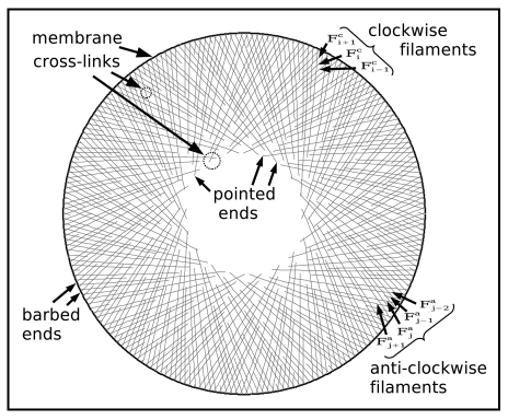
As a consequence of A1 and A2 the lamellipodium has the organization depicted in Figure 1.
Figure 1.
Constituent elements of the model.
There are two families of locally parallel filaments. Looking from the centre of the lamellipodium ring, the filaments in the first group bear to the left and the second group to the right; referred to as clockwise and anti-clockwise filaments. As a consequence of rotational symmetry, all filaments can be constructed from one reference filament (which, “without loss of generality,” we shall take clockwise) with the maximal filament length. All clockwise filaments can then be constructed by rotation of the reference filament and subsequent random cutting at the pointed end; correspondingly, all anti-clockwise filaments are created by reflection, rotation and cutting.
A central feature of the model is the description of production and decay of cross-links and integrins, consistent with dynamic association/dissociation of linkage molecules with the actin network, leading to the next assumption.
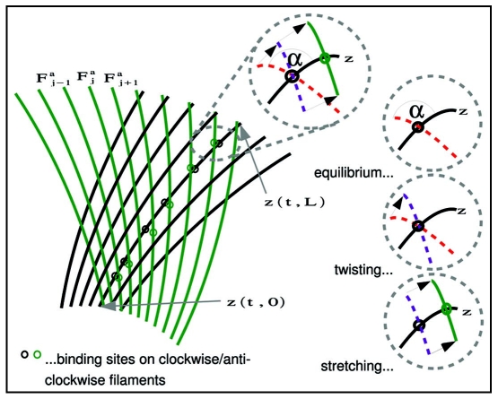
A4: A cross-link is an elastic connection between a clockwise and an anti-clockwise filament. The cross-link has both an elastic and a torsional component (Fig. 2 and Appendix). Cross-links form and break stochastically at the crossing between two filaments with at most one cross-link for any pair of filament crossing points at any time.
Figure 2.
Detailed view at cross-links.
With stable cross-links unrealistic deformations of the filament meshwork occur.
A5: An adhesion is an elastic link between a filament and a point on the substrate via a transmembrane linkage. Adhesions can form or break spontaneously, breaking being dependent on the degree of link extension.
A6: The cell membrane simulates an elastic rubber band stretched around the barbed ends of the filaments.
This assumption only serves to mimic a situation in which forces exerted on the barbed ends of filaments by the membrane are counteracted by the protrusive forces generated by polymerisation. To a first approximation the radius of the lamellipodium is determined by a balance of these forces. (A more thorough modeling of the size-determining mechanisms will be presented in a future study. One problem with this assumption is that membrane resistance increases with radius, which is probably not the case).
A7: The position of the filaments in time is determined by a quasistationary balance of elastic forces resulting from bending of the filaments, stretching and twisting the cross-links, stretching the adhesion linkages, and stretching the cell membrane.
The quasistationary assumption means that we neglect elastic oscillations, assuming that the filament network is damped by viscous forces in the cytosol and that the system therefore always operates at minimal potential energy. Thus, the evolution of the network is a consequence of actin polymerization dynamics together with the creation and breaking of cross-links and adhesions.
In summary, the model we present has two major ingredients (see Appendix for details): (1) the making and breaking of cross-links in the filament network and between the filaments and the matrix, based on renewal equations; and (2) minimisation of the potential energy of the system.
Simulation results.
We model a simple symmetrical cell with a hypothetical radius of slightly more then 8 µm, but with a realistic density of actin filaments and graded filament lengths.17 Realistic values for several of our model parameters can be found in the literature. Examples are the stiffness of filaments,19 the equilibrium angle between filaments and their total number17 and reaction rates of cross-links and integrins.20,21 For the latter, however, it turns out that our linear elasticity assumptions are a strong simplification from a microscopic point of view. Therefore approximate averaged values of elasticity parameters have been used.
For other quantities no reliable information seems to be available (in particular for in-vivo situations). For those we fixed values of a reasonable size such that a balance was reached between the forces of pushing at the periphery and the adhesion forces with the substrate. At the same time, both force components had to be low enough to prevent buckling of the actin filaments. Most notably the elasticity of the membrane, the on-rate of integrins βadh, and also the maximal density of integrins are determined with a view to get reasonable simulation results.
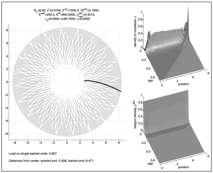
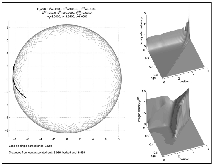
A typical long time (quasi-)equilibrium is shown in Figure 3. The left subfigure represents the lamellipodium where the position of the standard filament is drawn in black. Other filaments were created by rotating and/or reflecting the standard filament and introducing graded lengths to give a linear decrease in filament density from the tip to the base of the lamellipodium.17
Figure 3.
Long time solution.
The upper right picture represents the density of cross-links ρ depending on the position along the standard filament, where the value 0 represents the pointed end, and on the age. The lower right picture represents the density of integrins, ρadh, in an analogous way.
With respect to age both densities decay rapidly, but for different reasons: Cross-links break rapidly since their decay rate is rather high, cp. Table 2. On the other hand integrins are much more stable, but since the cell is in a non-moving state, they get stretched rapidly and, consequently, they are much more likely to break. This is modelled by a Boltzmann-factor according to Li, Moy.21
Table 2.
List of parameter rate constants
| Parameter | Value | Reference |
| v0 …polymerisation rate | 8 µm / min | |
| β …rate of cross-link (filamin) attachment | 1.3 sec−1 | c.p. Goldmann, Isenberg 1993 assuming 1µM of filamin |
| ζ …rate of cross-link (filamin) detachment | 0.6sec−1 | Goldmann, Isenberg 1993. |
| …max. density of integrins on a filament | 0.491 − 0.685 µm−1 | |
| βadh … rate of integrin attachment | 0.03sec7−1 | |
| ζadh … rate of integrin detachment | Li e.a. 2003 |
The solution tends to (quasi-)equilibrium very quickly, within the time necessary for two phases of treadmilling of the filaments.
In the long term the solution is stationary in the sense that the shape of the filaments and the density of cross-links do not change. However, there is a dynamic rotation of the clockwise filaments in clockwise direction and of the anti-clockwise filaments in anti-clockwise direction, corresponding to a bilateral flow of filament plus ends along the cell periphery. This lateral filament flow mimics that deduced for filaments in living cells, based on filament geometry and the observed lateral translation of filament bundles.17 Another feature found in lamellipodia already present in this simulation is a characteristic angle between filaments and between filaments and the membrane. Because of the presence of a preferred cross-link angle, this result is not very surprising (compare to Schaus et al.,15 where a preferred branching angle is used, too).
However, torsional stiffness of cross-links κT was not necessary to achieve short-term stability (12 min), but became relevant in the longer term (100 min).
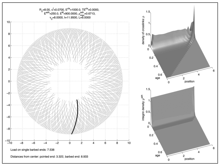
This, however, requires a balance between the forces mediated by adhesion with the substrate, the tangential forces exerted by cross-links and the radial ones exerted by the membrane (see simulation result Fig. 5) where we did the computation with .
Figure 5.
Solution without torsional stiffness.
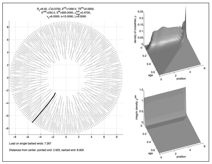
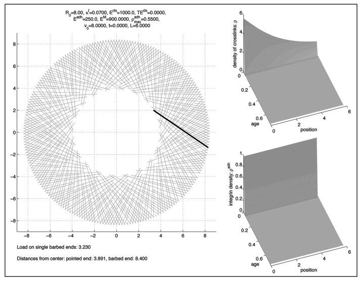
If we set the maximal density of integrins to a higher value, the meshwork collapses to a dense ring close to the membrane like in Figure 6, where we computed with . On the other hand, when we set the maximal integrin density to the smaller value , the meshwork disintegrates, since the filaments adopt a radial direction as in Figure 7.
Figure 6.
Collapse to a dense ring without torsional stiffness when adhesion is to strong.
Figure 7.
Dissolving lamellipodium without torsional stiffness when adhesion is to weak.
Finally, as observed by other authors,22 we compute forces per filament barbed end in the pN range.
Conclusion.
We have here attempted to model the organization of a continuously treadmilling lamellipodium. In contrast to other recent models (reviewed by Mogilner12), we assume that the actin filaments are continuously distributed, of variable length and stabilised in a network by cross-linking proteins. Recent studies by electron microscopy17 have not supported the idea that actin filaments in lamellipodia form a branched, dendritic array;5 therefore branches were not considered. In reality the lamellipodium is not truly 2 dimensional, but in the order of 0.2 µm thick. In the context of the present model, assumptions about cross-links between filaments are unaffected. However, transmembrane linkages to the substrate will only be possible for filaments closely apposed to the membrane. To assess the potential frequency of such linkages as well as the frequency of cross-links between filaments, new information about the three-dimensional arrangement of filaments in lamellipodia, by electron microscope tomography will be required. There are limitations to the present status of the model. Our current model does not consider how the actin network is generated in the first place, nor does it explain how filaments rearrange during different phases of protrusive activity.17 Also the effect of myosin is not incorporated yet, whose contractive effect might largely replace the strong mechanical effect of the cell membrane in the present model.
Nevertheless, it is interesting to note that filament reorientations can be induced by changing the substrate linkage constant. Further work will be required to integrate other parameters into the present scheme in order to develop a more comprehensive model of network dynamics.
Figure 4.
Initial condition zl.
Table 1.
List of parameters describing the actin-filament meshwork
| Parameter | Value | Reference |
| n … number of (anti-)clockwise filaments in the lamellipodium (2 × #F …total number) | 2200 | Koestler e.a. 2008 |
| R0 …equilibrium radius of the cell | 8µm | |
| L … maximal legnth of filaments | 6µm | |
| α … equilibrium angle of cross-links | 70° | |
| κM / (4π2) …stretching elasticity of the membrane | 900 pN / µm | |
| κB / (2 × n) …flexural rigidity of one filament | 7 × 10⁻²pN × µm2 | Gittes e.a. 1993 |
| κA / (2 × n) … stretching elasticity of one integrin-fibronectin complex | 250 pN / µm | cp. Oberhauser e.a. 2002; Li e.a. 2003 |
| κT / n2 … torsional stiffness one cross-link | 0 − 0.1 pN × µm | |
| η = η(t,s) …fraction of filaments present. |
Acknowledgements
This work has been supported by the Austrian Science Fund (FWF) through the Wissenschaftskolleg Differential Equations and by the Austrian Academy of Science. Furthermore it was supported by the WWTF-Project ‘How do cells move? Mathematical modeling of cytoskeletal dynamics and cell migration’ of C. Schmeiser and V. Small and by the Wittgenstein-2000 award of P. Markowich.
We also thank one of the referees for helpful advice.
Appendix
Mathematical formulation of the model.
In order to obtain a feasible mathematical description we will adopt a homogenisation limit, based on the assumption that the density of filaments within the lamellipodium is very high; we let the number of filaments tend to infinity in order to obtain a model based on continuous quantities instead of discrete ones.
With the maximal filament length L, an arc length parameterisation of the reference filament at time t is given by {z(t,s) : 0 ≤ s ≤ L} ⊂ R2, where s = 0 corresponds to the pointed and s = L to the barbed end. Occasionally we shall need the representation z(t,s) = |z(t,s)| (cos φ(t,s), sin φ(t,s)) in polar coordinates with the angle φ(t,s)∈S1. We expect |z(t,s)| to be strictly increasing with respect to s. Then |z(t,0)| is the inner radius of the lamellipodium and |z(t,L)| the radius of its leading edge at time t. As mentioned above, the reference filament is assumed to be clockwise, i.e., φ(t,s) is a strictly decreasing function of s. Note that |∂sz(t,s)| = 1.
For the parameterisation of the other filaments we need matrices of rotation and of reflection-rotation:
| (1) |
Assuming an equal number n of clockwise and anti-clockwise filaments, their parameterisations are given by where the pointed end parameters are (according to the rotational symmetry assumption) distributed identically such that
P(sci(t) ≤ s) = P(sai(t) ≤ s) = η(t,s), i, j = 0,…, n − 1,
where the given distribution function η satisfies η(t,0) = 0, η(t,L) = 1. It is not necessary for our purposes to describe the stochastic depolymerisation process in detail, since for large numbers of filaments only the distribution will be needed.
The arclength s is a geometric parameter. Because of the polymerisation at the barbed ends, polymerised actin molecules travel along the filament towards the pointed ends with the polymerisation speed denoted by v0. Because of this and because of the inextensibility assumption in A1, a Lagrange variable along the filaments is given by σ = s + v0t. In other words, the path of the actin molecule with label σ on the reference filament is given by z(t,σ − v0t). The fact that the filaments are depolymerised at the pointed ends is reflected by the assumption that saj(t) + v0t and sci(t)+ v0t are increasing functions of time. As a consequence, η(t,σ − v0t) is decreasing in t.
For the description of the kinematics of cross-links according to assumption A4 it will be sufficient to describe the cross-links between the reference filament and all anti-clockwise filaments. For this purpose we first have to find the crossings, which are unique due to A4. We compute
Then, if at time t there is a crossing point between the reference filament and the j th anti-clockwise filament, it is given by z(t,sj(t)) = Faj(t,sj(t)) where sj (t) is defined by φ(t,sj (t)) = -πj/n or φ(t,sj (t)) = π − πj/n.
If a cross-link between the reference filament and the j th anti-clockwise filament is created at time t*, then this happens at the crossing point. Once established, however, the two binding sites will move along the two filaments due to the treadmilling effect. Thus, at a later time t = t* + a, the binding sites will be located at z(t,sj (t − a) − v0a) and Faj(t,sj(t − a) − v0a), until the cross-link eventually breaks. We call a the age of the cross-link. Below we shall assume a resistance of cross-links against stretching and twisting. This means there are elastic forces related to the stretching
and to the twisting
where α is an equilibrium angle determined by the cross-link geometry.
The probability distribution of the cross-link with respect to age will be denoted by rj(t,a), where
| (2) |
| (3) |
is the probability that a cross-link between the reference filament and the j th anti-clockwise filament exists at time t. We postulate the following model for the evolution of the distribution:
This model has the standard form of age-structured population models (see, e.g., Perthame23). The differential equation describes ageing and breaking of cross-links, the boundary condition at a = 0 describes their creation. The dependence of the breaking rate on the physical distance between the binding sites (stretching) and the deviation from the equilibrium angle of cross-links (twisting) reflects that a cross-link might be broken by being loaded too much. The twisting dependence of the creation rate β could eliminate the possibility for a cross-link to be established, if the angle between the filaments differs from the equilibrium too much. Integration of the differential equation with respect to a shows that the second factor in the creation rate guarantees (2), i.e., the fact that there is at most one cross-link. Just as for the pointed-end (de)polymerisation process, all we need to know about the processes of creation and breaking of cross-links is the distribution rj.
The domain of the differential equation in (3) is determined by the requirement that both binding sites (on the reference filament and on the j th anti-clockwise filament) have not been depolymerised yet: sj (t − a) − v0a ≥ max{saj(t), sc0(t)}.
The next modeling step is the passage to a continuum description by letting the total number 2n of filaments tend to infinity. In the limit, the discrete rotation angles βj = 2πj/n, j = 0,…,n−1, are replaced by a continuous angle β ∈[0, 2π). Then we interpret the discrete filament positions and Fci(t,s) and Faj(t,s) as approximations for the values Fc(t,s,βi) and, respectively, Fa(t,s,βj) of continuous distributions
Fc(t,s,β) = R(β)z(t,s), Fa(t,s,β) = D(−β)z(t,s).
The distribution η(t,s) now gets a deterministic interpretation as the expected fraction of filaments in each angle element dβ, whose pointed end parameter at time t is smaller than s.
Similarly, the probability distribution rj(t,a) will be interpreted as an approximation of the expected cross-link density r(t,a,β) per filament at β = βj. In the following, however, cross-links will be described in terms of their arc length parameter and their age. A cross-link at arc length s and with age a at time t on the reference filament has been created at arc length s + v0a at time t − a, and it connects the reference filament to the anti-clockwise filament with parameter β = γ(t,s,a) := −2φ(t − a, s + v0a).
By the strict monotonicity of φ with respect to s, this relation can be used to replace the variable β by s. By dβ = ∂sγ ds, the cross-link density per filament in terms of s and a is given by ρ(t,s,a) = r(t,a,γ(t,s,a))∂sγ(t,s,a)).
The factor ∂sγ can be interpreted as density of crossing anti-clockwise filaments per unit length along the reference filament. From (3) and using ∂tγ + ∂aγ − v0∂sγ = 0, the transport equation for the cross-link density per angle-element becomes
| (4) |
with the boundary condition
where γ−1 is the inverse function of γ with respect to the argument s, i.e., , and the stretching and twisting terms are now given by
| (5) |
| (6) |
Note that the integration in the boundary condition has now been limited to the upper bound (L − s)/v0 for the age of a cross-link at position s. The rather complicated boundary condition can be simplified by the assumption that typical life times of cross-links will be small compared to other characteristic times for the network dynamics. We then approximate γ−1(t,a,γ(t,s,0)) by γ−1(t,0,γ(t,s,0)) = s, and ∂sγ(t,γ−1(t,a,γ(t,s,0)),a) by ∂sγ(t,s,0):
| (7) |
The boundedness property (2) of the microscopic cross-link density determined by (3) carries over to the modified model (4), (7). The accumulated distribution
satisfies the equation
preserving the property .
Taking into account the length distribution of the filaments, we arrive at the effective cross-link density
ρeff(t,s,a) = ρ(t,s,a)η(t,s)2,
where each of the two filaments involved in a cross-link contributes a factor η. Note that ρeff satisfies
hence the same type of transport equation as ρ but with a modified decay rate, which takes into account the loss of cross-links due to depolymerisation of the pointed ends. Recall that ∂tη − v0∂s is negative.
Concerning the dynamics of adhesion molecules (modeling assumptions A5), not only the assumptions are similar to the cross-links but also the model. The density ρadh(t,s,a) of adhesions per filament satisfies the differential equation
| (8) |
with the boundary condition
| (9) |
where the breaking rate ζadh depends on the stretching of the adhesions:
Sadh(t,s,a) = |z(t,s) − z(t − a,s + v0a)|.
The position of the filaments (supposition A7) finally will be formulated by assuming that the filament positions minimise a potential energy functional containing contributions from the above mentioned elastic effects:
U(t)[w] := Ubending (t)[w] + Usc1 (t)[w] + Utc1 (t)[w] + Uadh (t)[w] + Umembrane [w].
Here w(s)∈ R2, 0 ≤ s ≤ L, is a place holder for the reference filament position at time t.
The energy contribution from bending the filaments is taken in the standard form of linearised beam theory:
where κB can be interpreted as the product of the bending stiffness of one filament and the total number 2n of filaments. Note that 2nη(t,s) is the total number of filaments whose length is at least L − s.
Stretching the cross-links contributes the following energy term:
and similarly for twisting the cross-links:
The constants κS and κT are the products of 2n with Hooke constants describing the stretching and, respectively, torsional stiffnesses of the cross-link molecules.
The potential energy of the stretched adhesions is given by
Note that the evaluation of the adhesion energy at time t requires information on previous filament positions at all times between t − L/v0 and t. Actually, the same is true for the cross-link energies through the function γ(t,s,a) = -2φ(t − a,s + v0a).
The action of the cell membrane on the leading edge of the network (A6) leads to a model of the form
This models resistance against stretching the membrane above the equilibrium radius R0. We remark that κM/(4π2) is the force resulting from stretching the membrane by unit length. The force acting on any single barbed end is therefore given by the total force exerted by the membrane divided by the total number of barbed ends,
The position of the reference filament at time t is now determined by minimising the energy under the side condition that s is the arc length:
| (10) |
This concludes the derivation of the model. However, the formulation of a well posed problem still requires a start-up procedure. The problems (4), (7) and (8), (9) for the cross-link density and, respectively, for the adhesion density have to be supplemented by initial conditions
ρ(0,s,a) = ρI(s,a), ρadh(0,s,a) = ρadhI(s,a), 0 ≤ s ≤ L, 0 ≤ a ≤ (L − s)/v0.
Since, as mentioned above, the problem (10) for the determination of the filament positions is a delay problem, we need to prescribe
z(t,s) = zI(t,s), -L/v0 = t ≤ 0, 0 ≤ s ≤ L.
The knowledge of the history of the filament positions is necessary for specifying the binding sites of the cross-links and adhesions which are present initially. If, for example, initially only cross-links and binding sites with a maximal age ā < L / v0 are present, i.e., ρl(s,a) = ρadhl(s,a) = 0 for a > ā, then it is also sufficient to prescribe z(t,s) for −ā ≤ t < 0.
Numerical method.
We found that in order to perform simulations based on the model above, it was convenient to parameterise the set of admissible functions by making the ansatz
Hence for fixed t ≥ 0 the position of the reference filament is being described by the radius R(t) > 0 and the argument ω(t) ∈ R of the barbed end and by the tangential directions, which we represent by the angle-valued function ψ. With this representation not only the side condition |∂sz| = 1 is satisfied automatically, but also some of the energy terms are simplified. Most notably the bending component of the energy functional is then written as
and the twisting of cross-links (6) simplifies to
T(t,s,a) = 2ψ(t,s) + γ(t,s,a) − α.
This ansatz allows the direct application of techniques for unconstrained optimisation problems.
We performed simulations based on equidistant discretisations of time and arc length and present the numerical long time result
We start with the initial conditions and and ρl ≡ 0 and ρadhl ≡ 0 and alternate computing one timestep of the transport models for these densities and the minimisation step (10), where we start with a straight initial condition with arg zI(0) = −0.6 and arg zI(L) = -1/3 and |zI(L)| = 1.05 × R0 as depicted in Figure 3.
Footnotes
Previously published online as a Cell Adhesion & Migration E-publication: http://www.landesbioscience.com/journals/celladhesion/article/6373
References
- 1.Small JV, Stradal T, Vignal E, Rottner K. The lamellipodium: where motility begins. Trends Cell Biol. 2002;12:112–120. doi: 10.1016/s0962-8924(01)02237-1. [DOI] [PubMed] [Google Scholar]
- 2.Small JV, Isenberg G, Celis JE. Polarity of actin at the leading edge of cultured cells. Nature. 1978;272:638–639. doi: 10.1038/272638a0. [DOI] [PubMed] [Google Scholar]
- 3.Pantaloni D, Le Clainche C, Carlier MF. Mechanism of actin-based motility. Science. 2001;292:1502–1506. doi: 10.1126/science.1059975. [DOI] [PubMed] [Google Scholar]
- 4.Nakamura F, Osborn TM, Hartemink CA, Hartwig JH, Stossel TP. Structural basis of filamin A functions. J Cell Biol. 2007;179:1011–1025. doi: 10.1083/jcb.200707073. [DOI] [PMC free article] [PubMed] [Google Scholar]
- 5.Pollard TD. Regulation of actin filament assembly by Arp2/3 complex and formins. Annu Rev Biophys Biomol Struct. 2007;36:451–477. doi: 10.1146/annurev.biophys.35.040405.101936. [DOI] [PubMed] [Google Scholar]
- 6.Carlier MF, Pantaloni D. Control of actin assembly dynamics in cell motility. J Biol Chem. 2007;282:23005–23009. doi: 10.1074/jbc.R700020200. [DOI] [PubMed] [Google Scholar]
- 7.Mogilner A. On the edge: modeling protrusion. Curr Opin Cell Biol. 2006;18:32–39. doi: 10.1016/j.ceb.2005.11.001. [DOI] [PubMed] [Google Scholar]
- 8.Alt W, Dembo M. Cytoplasm dynamics and cell motion: Two-phase flow models. Math Biosci. 1999;156:207–228. doi: 10.1016/s0025-5564(98)10067-6. [DOI] [PubMed] [Google Scholar]
- 9.Gracheva ME, Othmer HG. A continuum model of motility in ameboid cells. Bull Math Biol. 2004;66:167–193. doi: 10.1016/j.bulm.2003.08.007. [DOI] [PubMed] [Google Scholar]
- 10.Mogilner A, Marland E, Bottino D. A Minimal Model Of Locomotion Applied To The Steady Gliding Movement Of Fish Keratocyte Cells [Google Scholar]
- 11.Rubinstein B, Jacobson K, Mogilner A. Multiscale two-dimensional modeling of a motile simple-shaped cell. Multiscale Model Simul. 2005;3:413–439. doi: 10.1137/04060370X. [DOI] [PMC free article] [PubMed] [Google Scholar]
- 12.Mogilner A, Oster G. Cell Motility Driven by Actin Polymerization. Biophysical Journal. 1996;71:3030–3045. doi: 10.1016/S0006-3495(96)79496-1. [DOI] [PMC free article] [PubMed] [Google Scholar]
- 13.Lacayo CI, Pincus Z, VanDuijn MM, Wilson CA, Fletcher DA, Gertler FB, Mogilner A, Theriot JA. Emergence of Large-Scale Cell Morphology and Movement from Local Actin Filament Growth Dynamics. PLoS Biol. 2007:5. doi: 10.1371/journal.pbio.0050233. [DOI] [PMC free article] [PubMed] [Google Scholar]
- 14.Maly IV, Borisy GG. Self-organization of a propulsive actin network as an evolutionary process. Proc Natl Acad Sci. 2001;98:11324–11329. doi: 10.1073/pnas.181338798. [DOI] [PMC free article] [PubMed] [Google Scholar]
- 15.Schaus TE, Taylor EW, Borisy GG. Self-organization of actin filament orientation in the dendritic-nucleation/array-treadmilling model. Proc Natl Acad Sci USA. 2007;104:7086–7091. doi: 10.1073/pnas.0701943104. [DOI] [PMC free article] [PubMed] [Google Scholar]
- 16.Marée AFM, Jilkine A, Dawes A, Grieneisen VA, Edelstein-Keshet L. Polarization and movement of keratocytes: a multiscale modeling approach. Bull Math Biol. 2006;68:1169–1211. doi: 10.1007/s11538-006-9131-7. [DOI] [PubMed] [Google Scholar]
- 17.Koestler SA, Auinger S, Vinzenz M, Rottner K, Small JV. Differentially oriented populations of actin filaments generated in lamellipodia collaborate in pushing and pausing at the cell front. Nat Cell Biol. 2008 doi: 10.1038/ncb1692. [DOI] [PubMed] [Google Scholar]
- 18.Verkhovsky AB, Svitkina TM, Borisy GG. Self-polarization and directional motility of cytoplasm. Current Biology. 1998;9:11–20. doi: 10.1016/s0960-9822(99)80042-6. [DOI] [PubMed] [Google Scholar]
- 19.Gittes F, Mickey B, Nettleton J, Howard J. Flexural rigidity of microtubules and actin filaments measured from thermal fluctuations in shape. Journal of Cell Biology. 1993;120:923–934. doi: 10.1083/jcb.120.4.923. [DOI] [PMC free article] [PubMed] [Google Scholar]
- 20.Goldmann WH, Isenberg G. Analysis of filamin and alpha-actinin binding to actin by the stopped flow method. FEBS Lett. 1993;336:408–410. doi: 10.1016/0014-5793(93)80847-n. [DOI] [PubMed] [Google Scholar]
- 21.Li F, Redick SD, Erickson HP, Moy VT. Force measurements of the alpha5beta1 integrin-fibronectin interaction. Biophysical Journal. 2003;84:1252–1262. doi: 10.1016/S0006-3495(03)74940-6. [DOI] [PMC free article] [PubMed] [Google Scholar]
- 22.Mogilner A, Oster G. Force Generation by Actin Polymerization II: The Elastic Ratchet and Tethered Filaments. Biophysical Journal. 2003;84:1591–1605. doi: 10.1016/S0006-3495(03)74969-8. [DOI] [PMC free article] [PubMed] [Google Scholar]
- 23.Perthame B. Transport equations in biology. Basel: Birkhäuser Verlag; 2007. [Google Scholar]


