Abstract
Purpose
To develop an imaging and visualization technique for real-time magnetic resonance angiography (rt-MRA) fully integrated with a real-time interactive imaging environment on a clinical MR scanner.
Materials and Methods
Intraarterial injections of contrast agent and imaging processing techniques were employed for rapid catheter-directed assessment of vessel patency and regional tissue perfusion. Operators can image multiple thin slices to maximize anatomic detail or use thick slice or projection imaging to maximize vessel coverage. Techniques in both pulse sequence and image processing were employed to ensure background suppression. Accumulation of maximum pixel values allows persistent display of bolus signal as it passes through the vessels and into tissues. Automatic brightness adjustment was used to ensure visibility at all stages of bolus passage.
Results
Experimental intraarterial rtMRA of coronary, renal, and carotid arteries show that vessel trajectories and perfusion territories are well visualized in swine. Switching between standard real-time imaging and rtMRA imaging after contrast injection was easy to perform during a procedure without stopping the scanner.
Conclusion
The proposed technique facilitates visualization of intraarterial contrast injections using real-time MRI. Although designed for rapid deployment during rtMRI-guided interventional procedures, the technique may also be useful to supplement the study of vessel anatomy, flow, or perfusion.
Keywords: real-time, angiography, interventional, cardiovascular
DIGITAL SUBTRACTION ANGIOGRAPHY (DSA) (1–5) is a technique successfully used in x-ray angiography to suppress background and enhance visualization of an intravascular contrast agent. Applying a similar technique with real-time magnetic resonance angiography (rtMRA) has been challenging especially in coronary vessels due to cardiac and respiratory motion and the relatively low spatial and temporal resolution of MRI compared to x-ray. However, MRI offers important advantages over conventional x-ray fluoroscopic image guidance, including superior soft-tissue visualization and thin-slice imaging. Advances in real-time MRI imaging systems have improved feasibility for use in therapeutic interventions. For catheter-based procedures, there has been substantial interest in exploiting MR imaging techniques to improve vessel visualization. Some groups have shown promising results imaging vessel lumina using intraarterial injections of a T1-shortening contrast agent coupled with a dynamically updated T1-weighted imaging sequence (6–8).
This work focuses on real-time imaging of intraarterial injections of contrast agent utilizing a combination of interactive pulse sequence modifications and image processing for additional background suppression and persistent vessel rendering. These features are seam-lessly integrated with a real-time imaging platform for streamlined use in MRI-guided catheter-directed procedures. The injections are hand driven and brief, as is customary with x-ray angiography. The path of the contrast agent is immediately visible in the real-time images. The operator can switch between standard real-time imaging to rtMRA-enhanced imaging without stopping the scanner.
In this technique, background suppression is achieved using nonselective saturation preparation, and the temporal maximum for each background-suppressed pixel is used to create a reference image, analogous to creation of a mask image in DSA. The reference image values are then subtracted from real-time images to depict the path of injected contrast agent and temporal maxima are displayed. Contrast agent is present in the vessels for a short period of time, but the temporal maximum intensity projection (timeMIP) images depict these structures with persistence as they are painted in real-time by the contrast bolus. This is similar to the ‘maximum-hold’ technique used in ultrasound to render small blood vessels (9). The technique can be switched on or off during the scan, allowing quick employment during an injection and resumption of standard real-time imaging without stopping the scanner. Thick slices may be used to ensure vessel coverage, or multiple thin slices to increase anatomic detail. The technique works well even in the absence of saturation preparation. Applications include rapid intraprocedure assessment of blood vessel patency during rtMRI-guided recanalization (10), and mapping of regional perfusion territories.
MATERIALS AND METHODS
Creation of Reference Images
Background suppressed real-time imaging of the contrast agent is achieved in this work through the creation of a sequence of timeMIP images, g(n), for n = 0, 1, 2…, from the real-time background-suppressed magnitude images, f ’(n). First, saturation preparation is enabled for background suppression, wherein a nonselective 90° radiofrequency (RF) pulse is played before each image acquisition. Complex subtraction during image reconstruction was available for additional or alternate background suppression, but was not used to generate any of the results described herein. Background suppression requires a few image acquisitions to stabilize, especially during a multiple-slice scan or when using view sharing for frame rate acceleration. For view sharing rate 2, image reconstructions were done two times for every complete coverage of k-space, alternately acquiring the even then the odd phase-encoding lines. Motion causes ghosts with this acceleration method, but the ghosts appear away from the region of interest.
An image counter is started, n = 0, and the temporal maximum value for each background-suppressed image pixel is stored. These temporal maxima images are observed to ‘fill-in’ with rectified noise and unsuppressed background signal and stabilize after several image acquisitions. The temporal maxima image acquired at n = nref is used as a reference image, given by:
The value of nref was chosen empirically to allow a short time for stabilization and was set to 12 for all results shown here. Too small a value of nref compromises background suppression; too large a value increases the waiting time before injection and does not significantly change the reference image or the results.
Creation of timeMIP Images
The timeMIP images are calculated by subtracting the reference image from subsequent background-suppressed images and saving the temporal maximum for each pixel:
where R(•) is the ramp function, which passes positive values and clamps negative values to 0. The effect of this operation is to show only pixel values that become brighter after nref by an amount greater than the reference value for that pixel.
After nref, the physician was signaled to inject the contrast agent and the real-time results were seen in the timeMIP images, g(n > nref).
The same scheme was used for multiple slice acquisitions, with nonselective saturation preparation pulses played before each image acquisition and separate timeMIP images calculated for each slice position. View sharing was used to increase the imaging frame rate and to increase the frequency at which saturation preparation was performed, which improved the background suppression.
Since the brightness of the timeMIP images increases significantly during an injection, automatic image brightness compensation was available to facilitate visualization of all phases of the injection. When enabled, the timeMIP image pixel values were scaled so that the maximum pixel value matches the maximum image brightness. This results in higher scaling for the early phases, allowing better contrast visualization, but at the cost of background noise amplification, which is reduced in later phases.
Experiments
This technique is designed for rapid deployment during an interventional procedure. Thus, we used an injection protocol that would be simple to perform multiple times as necessary. Injections were administered manually using a 5 cc syringe filled with 10–15 mM Gd-DTPA (Magnevist, Berlex Laboratories, Wayne, NJ). The injection duration was 1–3 seconds, depending on the resistance encountered.
Several different in vivo experiments were performed in swine to demonstrate this technique, all employing manual intraarterial injections of dilute Gd-DTPA during real-time imaging. Nonsurvival animal experiments were approved by the NHLBI Animal Care and Use Committee using mini-swine (mean weight 40 kg), performed under general anesthesia with inhaled isoflurane, and used percutaneous arterial catheter access. All injections were performed with modified, MRI-visible 6 or 7F catheters that were navigated to their target destination using rtMRI guidance.
The following experimental scenarios were investigated, with the number of experiments performed in parentheses:
Injection into brachiocephalic artery to visualize bilateral carotid arteries (6).
Injection into renal artery to see kidney perfusion (2).
Injection into a coronary artery (left anterior descending) to see the vessel and its perfusion territory (2).
Injection into carotid artery during a therapeutic intervention to confirm successful recanalization of chronic occlusion (4).
Experiments were performed in a 1.5T Sonata scanner (Siemens Medical Systems, Erlangen, Germany), using the standard Body Matrix phased-array coil (six elements), and two Spine Matrix coils (three elements each). Typical imaging parameters were: SSFP sequence with TR/TE = 3.4/1.7 ms, 8 mm slice, 192 × 108 matrix, 800–1200 Hz/pixel bandwidth, 3/4 partial phase k-space coverage, view sharing rate 2–4, yielding a frame rate of 7–12 per second, divided among the slices. Any slice could be enabled or disabled interactively as needed. Multiple oblique images were displayed at their respective locations in a 3D rendering (11). Electrocardiogram (ECG) triggering was available to avoid artifacts from cardiac motion and was used for the multiple-slice coronary injection experiment.
RESULTS
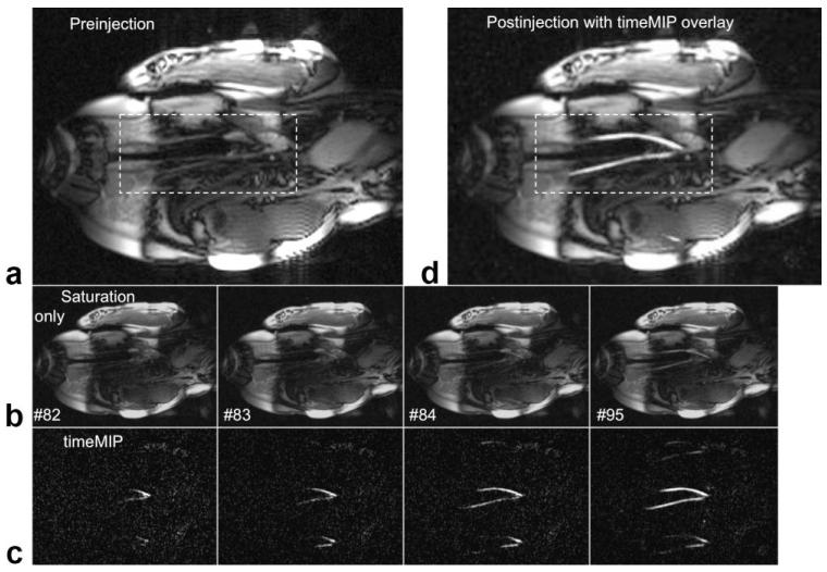
Figure 1 shows a basic experiment used to test the technique. A single coronal slice (6 mm) was prescribed containing the left carotid and innominate vessels. The timeMIP images show the Gd-DTPA contrast bolus in the vessels with effective background suppression, providing clear depiction of both carotid vessels even though the saturation was suboptimal. The contrast bolus immediately fades from the saturated images, but is displayed with persistence in the timeMIP images. Ghosting artifacts from rate 3 view sharing occurs after definition of the reference and are thus not suppressed. However, these ghosts are away from the objects of interest and do not impede view of the vessels. Once the contrast bolus has passed the timeMIP function and image saturation were turned off. The final timeMIP image was available for recall and overlay (grayscale or color) on the real-time image whenever desired.
Figure 1.
Real-time images showing intraarterial contrast injection into the innominate artery, which supplies the carotids. a: One frame from coronal RT image stream just before saturation is turned on. b: Images with saturation turned on (brightness increased), acquired during injection and displayed in real-time with frame number shown. c: timeMIP images for the same frame numbers. Brightness is adjusted automatically, decreasing the visible noise as the vessels fill. Both carotid vessel lumens are clearly seen as the contrast agent flows with the blood. Ghosting from rate 3 view sharing is evident above and below the vessels, but does not interfere with vessel visualization. b: The timeMIP image from frame #95 is overlaid on a real-time image; color overlay was also possible.
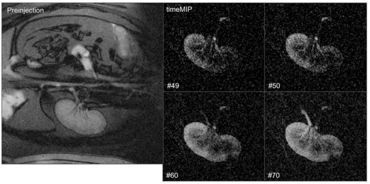
In Figure 2, renal imaging was performed at a higher spatial resolution with a 256 × 192 matrix, 280 mm field of view (FOV), and 6 mm slice thickness with rate 2 view sharing. Inflow, perfusion, and outflow are observed in real-time during a 5 cc bolus hand injection of 10 mM Gd-DTPA. In this experiment, respiratory motion in the S/I direction (L/R in the images) caused a smearing in the timeMIP images.
Figure 2.
Real-time images showing intrarenal artery contrast injection. Left: Before enabling nonselective saturation. Right: Select time-MIP images (zoomed, frame number shown) showing renal perfusion and drainage via the ureter.
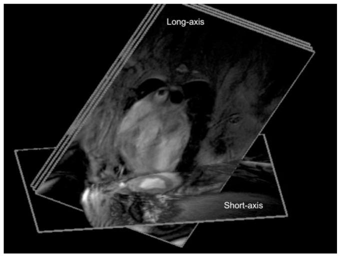
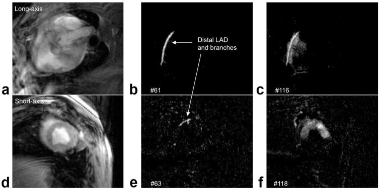
Figures 3 and 4 (and Suppl. Movie 1) show results from an injection directly into the left anterior descending (LAD) coronary artery. A 192 × 108 matrix was used for higher temporal resolution, with rate 2 view sharing, 300 mm FOV, and 8 mm slice thickness. Multiple slices were used for views of the LAD and perfusion territory. In Fig. 4b,e the contrast agent is seen in the LAD and entering branches. Figure 4c,f shows two views of the perfusion territory, in this case the anterior wall and septum.
Figure 3.

Image planes used for intracoronary contrast agent injection consisted of three parallel long-axis images, containing the LAD, and one short-axis image to show perfusion.
Figure 4.
ECG-gated real-time images are acquired during intracoronary contrast agent injection, showing LAD in the middle long-axis slice (top row, a—c) and short-axis slice (bottom row, d—f). a,d: Before injection, with no saturation preparation. b,e: timeMIP images show contrast in the LAD and some branches. c,f: Contrast agent perfuses the myocardium.
In Fig. 5 we show the utility of this technique during an interventional procedure under rtMRI guidance. Specifically, we performed rtMRI-guided chronic total occlusion (CTO) recanalization in swine using modified CTO guidewires and guide catheters (10). Imaging parameters were 224 × 176 matrix, 12 mm slice, 260 mm FOV, and rate 4 view sharing for selective intraarterial injections that were used to verify that the guide wire and catheter have traversed the carotid occlusion (Fig. 5c). After balloon inflations at several locations throughout the occluded region, real-time images of an injection from a more proximal position clearly showed brisk antegrade flow through the artery (Fig. 5d). This technique provided rapid visual assessment of vessel patency during rtMRI-guided recanalization, without interrupting the scanner.
Figure 5.
Intraarterial contrast injections after recanalization of a chronic total occlusion. a: Coronal MRA using standard (systemic intravenous) clinical techniques showing occluded left carotid artery. In this MIP angle the vertebral artery partly overlies the occluded L carotid artery. b: RT image frame after guidewire and catheter have traversed occlusion. Arrow indicates approximate catheter tip position. c: timeMIP image showing contrast injection through catheter, indicating catheter has reentered the lumen distal to the occlusion. Noise is higher due to faint signal and automatic brightness adjustment. d: After several balloon inflations, the catheter is positioned proximally and timeMIP view of injection indicates successful angioplasty, verified by MRA (not shown). Some ghosting from rate 4 view sharing is visible.
DISCUSSION
With ECG gating it was possible to see both major and minor branches of coronary vessels as well as myocar-dial perfusion territories, all displayed at their respective locations in 3D. Real-time imaging of arteries and their perfusion territories may have value in defining regional collateral-dependent myocardial territories and the impact of investigational biological treatments. The multiple slice capability allowed visualization of tortuous vessels and separate perfusion territories simultaneously.
Complex subtraction for additional or alternative background suppression was available but not used to generate any of the results shown. Further work will focus on any benefits provided by complex subtraction. Motion of unsaturated tissue during the formation of the reference image will increase pixel values of the reference image in the area covered by the motion. This ensures that the background will be subtracted off in any phase of the cardiac or respiratory cycles. Thus, we choose a value of nref large enough such that images are collected at various points during these cycles. However, motion during collection of the timeMIP images causes smearing that is minimal in peripheral vessels, but must be reduced by ECG gating in vessels in or near the heart.
In conclusion, we have developed and demonstrated a method for real-time visualization of intraarterial contrast injections, which is seamlessly integrated into a real-time imaging platform. This imaging mode may be enabled and disabled during real-time imaging without stopping the scanner. Excellent visualization of the contrast agent was demonstrated in coronary and peripheral vessels and selective perfusion. The timeMIP images exhibit effective background suppression for isolation of the contrast agent. This technique could be of benefit both to anatomical studies and therapeutic interventions.
Supplementary Material
ACKNOWLEDGMENT
The authors thank Joni Taylor and Ranil DeSilva for valuable assistance.
Contract grant sponsor: Intramural Research Program of the National Heart Lung and Blood Institute, NIH, DHHS.
Footnotes
Additional Supporting Information may be found in the online version of this article.
REFERENCES
- 1.Mistretta CA, Crummy AB. Diagnosis of cardiovascular disease by digital subtraction angiography. Science. 1981;214:761–765. doi: 10.1126/science.7292009. [DOI] [PubMed] [Google Scholar]
- 2.Runge VM, Kirsch JE, Lee C. Contrast-enhanced MR angiography. J Magn Reson Imaging. 1993;3:233–239. doi: 10.1002/jmri.1880030135. [DOI] [PubMed] [Google Scholar]
- 3.Lossef SV, Rajan SS, Patt RH, et al. Gadolinium-enhanced magnitude contrast MR angiography of popliteal and tibial arteries. Radiology. 1992;184:349–355. doi: 10.1148/radiology.184.2.1620827. [DOI] [PubMed] [Google Scholar]
- 4.Wang Y, Johnston DL, Breen JF, et al. Dynamic MR digital subtraction angiography using contrast enhancement, fast data acquisition, and complex subtraction. Magn Reson Med. 1996;36:551–556. doi: 10.1002/mrm.1910360408. [DOI] [PubMed] [Google Scholar]
- 5.Frayne R, Grist TM, Korosec FR, et al. MR angiography with three-dimensional MR digital subtraction angiography. Top Magn Reson Imaging. 1996;8:366–388. [PubMed] [Google Scholar]
- 6.Tsekos NV, Woodard PK, Foster GJ, et al. Dynamic coronary MR angiography and first-pass perfusion with intracoronary administration of contrast agent. J Magn Reson Imaging. 2002;16:311–319. doi: 10.1002/jmri.10161. [DOI] [PubMed] [Google Scholar]
- 7.Green JD, Omary RA, Finn JP, et al. Two- and three-dimensional MR coronary angiography with intraarterial injections of contrast agent in dogs: a feasibility study. Radiology. 2003;226:272–277. doi: 10.1148/radiol.2261011848. [DOI] [PubMed] [Google Scholar]
- 8.Gui D, Tsekos NV. Fast magnetization-driven preparation for imaging of contrast-enhanced coronary arteries during intra-arterial injection of contrast agent. J Magn Reson Imaging. 2006;24:1151–1158. doi: 10.1002/jmri.20728. [DOI] [PubMed] [Google Scholar]
- 9.Kamiyama N. Update of ultrasound contrast imaging. International Congress Series. 2004;1274:53–56. [Google Scholar]
- 10.Raval AN, Karmarkar PV, Guttman MA, et al. Real-time MRI-guided endovascular recanalization of chronic total arterial occlusion in a swine model. Circulation. 2006;113:1101–1107. doi: 10.1161/CIRCULATIONAHA.105.586727. [DOI] [PMC free article] [PubMed] [Google Scholar]
- 11.Guttman MA, Lederman RJ, Sorger JM, McVeigh ER. Real-time volume rendered MRI for interventional guidance. J Cardiovasc Magn Reson. 2002;4:431–442. doi: 10.1081/jcmr-120016382. [DOI] [PMC free article] [PubMed] [Google Scholar]
Associated Data
This section collects any data citations, data availability statements, or supplementary materials included in this article.


