Abstract
Inorganic nanoparticles (NPs) display unique size-dependent properties and have applications in many different areas such as medicine and the semiconductor industry. In order to take advantage of these properties, the organization of the NPs must be controlled, either to promote crystallization or to prevent agglomeration. This control is typically acheived by using covalently bound amphiphilic ligands. While the properties of the NPs themselves have been well-characterized, much less is known about the organic ligand coating. Here we present a theoretical and computer simulation approach to compute the surface area occupied per ligand molecule as a function of the NP radius and of the ligand hydrophilic to lipophilic balance. We employ a self-consistent method which takes into account the full free energy of the NP/ligand/solvent system, which for this study is composed of a hydrophobic NP, alkyl poly(oxyethylene) ligands, and water. We find an order of magnitude higher ligand coverage on NPs compared to flat surfaces, in agreement with some experimental reports. Our approach is fundamentally different from existing computational methods in the literature and builds a foundation for studies of the organization of colloidal NPs in solvents or at interfaces.
Introduction
Nanoparticles (NPs) have size-dependent optical, magnetic, and electronic properties due to quantum confinement effects and to their surface area to volume ratio. In order to take advantage of these properties, the organization of the NPs must be controlled. For example, to build new photonic band gap materials the NPs must be assembled into specific non-close-packed crystal structures.1 Self-assembly is considered to be the best route to direct this organization and is implemented by making colloidal dispersions of the NPs in which organic surfactant molecules are attached to the NP surface.2,3 Conversely, for biological imaging applications the NPs must not aggregate; this control is acheived once again by using surfactant molecules attached to the NP surface, this time to impart colloidal stability.4
The structure and organization of the organic surfactant, also referred to as the ligand, coating on the inorganic NP is of crucial importance to the success of NP organizational control and self-assembly efforts. Experimental techniques are, with rare exceptions, 5 unable to examine the organic coating. Computer modeling can make significant contributions to this problem, particularly because of its capacity to model systems in their native environment; in contrast, most experimental techniques require crystallization, solvent removal, or deposition on a substrate, all of which can alter the relevant morphology.
One of the most fundamental questions, in performing such computer modeling, is to ask how many surfactant molecules are attached to a given NP. It is known from thermogravimetric analysis that the ligand grafting density strongly depends on the curvature of the NP surface. 6 Our goal in this study is to systematically estimate grafting densities as a function of NP size and of surfactant architecture (hydrophilic/lipophilic balance). The motivation is to study the role of curvature on ligand organization around NPs. This task will be accomplished in two ways: 1) A new free energy method is introduced to measure the optimal surfactant coverage using realistic molecular dynamics computer simulations, and 2) the theory of surfactant self-assembly due to Nagarajan and Ruckenstein is modified to include NPs and applied to predict the grafting density. 7 We will compare and contrast the results from these two approaches.
This approach is fundamentally different from the existing simulation methods in the literature. Most studies derive from the method of Luedtke and Landman8 in which gas-phase butanethiol molecules are adsorbed onto a gold NP surface using an energy criterion; longer ligand chains are subsequently grown from these attachment points. The grafting density is solely determined by the initial butanethiol adsorption density. An even simpler scheme is used by Ghorai and Glotzer9 in which the ligand grafting density is taken to be a constant, independent of the NP radius. Our approach uses the full free energy of the NP/ligand/solvent system to self-consistently optimize the ligand grafting density, and we find that this density has a strong dependence on the NP radius, which is also often observed experimentally.6,10 Patel and Egorov11 come closest to our approach: they simulate the adsorption of ligand chains onto the NP surface beginning with a bare NP, but surprisingly they fail to report the resulting number of attached chains.
The simulation approach defines the inter- and intra-molecular forces and computes the free energy from these forces whereas the theoretical approach directly postulates the form of the free energy expressions. Both approaches have their strengths and weaknesses. The strength of the simulation approach is that it is not necessary to account for all the different contributions to the free energy of the system; the free energy emerges from the potential energy expressions in the force field and from the configurational entropy. The weakness of this approach lies in the accuracy of the force field. The strength of the theoretical approach is that the free energy expressions are physically motivated and offer great insight into the phenomenon under study. The weakness of this approach is that terms may be missing from the free energy expressions, or may be too simple or coupled in ways that are not accounted for.
The surfactants employed in this study are nonionic alkyl poly(oxyethylene) chains, 12 which are among the most extensively used surfactants. In terms of colloidal properties, nonionic surfactant stabilization is more robust than electrostatic stabilization, providing stability for a longer time and at higher NP concentrations.13
The rest of the paper is organized as follows. The Molecular Dynamics Calculations section contains an exposition of the MD modeling studies including the derivation of the force field and the novel free energy method. The Theoretical Calculations section discusses the implementation of the theoretical method due to Nagarajan and Ruckenstein.7 The computational and theoretical methods are compared in the Discussion section, following by concluding remarks.
Molecular Dynamics Calculations
The force field
A coarse grain (CG) force field is employed to describe the intra- and intermolecular interactions. A CG treatment is most appropriate for this study: it retains a discrete, realistic molecular representation of the chemical species but is not so detailed as to obsure the essential physics of the system.14 We refer the reader to two review articles for an in-depth discussion of the role of CG methods in molecular modeling.15,16
In the systems under study, let us label the surfactant and the solvent as component A, and the inorganic NP as component B. The molecular interactions are divided into two classes: A-A and A-B.17 The first class of interactions is modeled using the CG force field of Shinoda 18,19 which includes harmonic bond and bend potentials to connect the CG beads representing a surfactant molecule. The second class of interactions is constructed from fully atomistic computer simulation data and will now be described in detail. Before we do this, it is worth pointing out that the two classes of interactions each give rise to a force field. One could ask whether or not these two force fields can simply be added together or need to be combined in a more sophisticated manner to make them compatible. In this sense what we have done can be considered as a “first-generation” model.
The A-B interaction is coarse grained in two steps: first the NP is coarse grained and then the ligand and solvent are coarse grained. For the first step, the NP is assumed to consist of crystalline or amorphous atoms in the overall shape of a sphere. To find the potential energy of interaction between the entire NP and an individual atom in the ligand/solvent, the nonbonded Lennard-Jones interaction between each NP atomic site i and the ligand/solvent atom in question should be summed, as depicted in Figure 1. The sum can be replaced with an integral by smearing out the NP atomic sites to obtain,
| (1) |
with P(d,r) = (15d6 + 90d5r + 288d4r2 + 552d3r3 + 648d2r4 + 432dr5 + 128r6) where r is the NP spherical core radius, d is the distance between the NP and the ligand/solvent atom, and ρ is the number density of NP atomic sites (see Figure 1). The values for ε and σ are taken from the CHARMM atomistic force field20 using the CA aromatic carbon atom for the NP atom type, yielding a hydrophobic NP; ρ is taken to be 0.113 Å-3. We have chosen to consider a hydrophobic NP because we are interested, in future studies, in colloidal stability.
Figure 1.
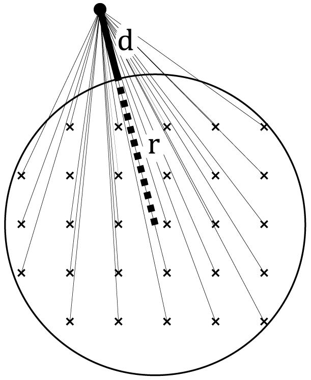
Schematic of the interaction between an atom in the ligand/solvent and the entire NP. The NP consists of atoms in a crystalline (shown here) or amorphous arrangement with an overall spherical shape of radius r.
This type of integral approximation is commonly used for flat solid surfaces in MD simulation studies21-23 and is analogous to Hamaker’s method.24
In the second step the ligand/solvent atom - NP interactions are coarse grained. This step involves changing the level of resolution of the ligand/solvent molecules by replacing a collection of atoms with a single effective particle at their center of mass; see Figure 2 for an illustration of the atoms and their corresponding coarse grain representation for the C12E8 ligand. Conceptually, the CG procedure consists of finding the effective interaction between the center of mass of this collection of atoms and the NP. To do this, the tools of probability theory and statistical mechanics are employed. A probability distribution P is defined from the potential energy U by P = e-βU where β is the inverse of the Boltzmann constant times the temperature. There is a one-to-one relationship between probability density and potential energy which will let us recover the potential energy from the probability density at the end of the calculation. The collection of atoms belonging to a single coarse grain unit is depicted, schematically, by the 5 light grey circles in Figure 3. Their center of mass (COM) is shown by the larger circle with an X through it. Our goal is to compute the probability of finding the COM a distance d (equal to the length of vector n in Figure 3) from the NP. There are two types of interactions to consider: the individual atom - NP interactions U(d,r), and the interactions between the ligand/solvent atoms themselves. These latter interactions are strong because the atoms corresponding to a CG unit are usually attached to each other by covalent bonds (see Figure 2). The two types of interactions are independent of each other because of the widely accepted use of effective two-body non-bonded forces in condensed matter atomistic force fields. In the language of probability theory, this implies that the corresponding probabilities are multiplicative. Conceptually, then, the probability of finding the COM a distance d from the NP is given by
| (2) |
where the integrand consists of the probability of finding each individual atom i a distance di from the NP, and jointly the probability PI of finding the atoms in this arrangement relative to each other (I for internal, or intra-CG interactions). The integration (simply denoted by dx) is understood to be over all atomic coordinates consistent with the condition that the COM is a distance d from the NP. In other words, we must integrate over all possible atomic and NP coordinates with NP-COM distance d, with each configuration contributing to P(d) with a weight given by the integrand. Since PI is a probability density, we can appeal to the theory of importance sampling to rewrite P(d) as
| (3) |
where PI now plays the role of the weighting function.25 Sampling from PI is performed using an equilibrium MD simulation of the soft matter portion (ligand and solvent) of the system, without the presence of the NP. This is because the contributions due to the NP are accounted for in the exp(-βUi(di)) terms. To be explicit, we will now give the sampling algorithm used to compute P(d).
Figure 2.
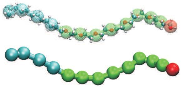
The diblock copolymer octaethylene glycol monododecyl ether, C12E8, is shown in atomistic detail (top) and at the coarse grain level of representation (bottom). The atoms corresponding to coarse grain units are indicated with transparent spheres in the top picture (cyan: alkane, green: ethylene glycol, red: hydroxyl terminus).
Figure 3.
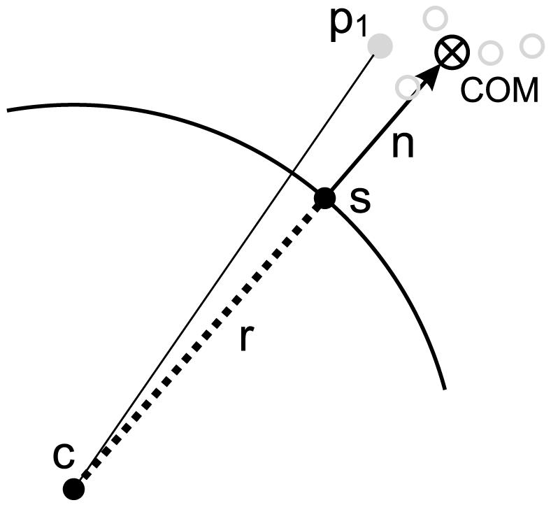
Illustration of the sampling algorithm for the construction of the coarse grain force field, in which five atoms (light grey) are replaced by their center of mass (COM). The spherical NP has center c and radius r. The length of the vector n is d. Refer to the text for details.
Since there is no NP present in the soft matter simulation, it must be introduced (as a ghost) to build the required distributions. What is known is that the COM of the atoms corresponding to the CG fragment of interest should be a distance d from the NP. Hence we sample a point s according to ∥COM - s∥ = d, namely we choose a point s on the surface of the sphere of radius d centered at COM. Since this point s is the nearest point on the NP to COM, we know that the vector n = COM - s (of length d) shown in Figure 3 is normal to the NP surface, and hence that the center of the NP is at c = s - r(n/∥n∥), namely a distance r from s in the direction opposite to n. This information is used to compute di for each atom i in the CG unit by di = ∥pi - c∥ - r where pi represents the cartesian coordinates of atom i. This procedure allows us to construct the integrand and estimate the integral P(d) by Monte Carlo sampling from an atomistic soft matter trajectory.
For each value of d we sample over s, namely the placement of the NP relative to the CG unit, and over realizations of the CG internal coordinates from an atomistic MD trajectory.
For each surfactant/solvent CG bead type and each NP radius r, 1000 grid points are used from r to r + 20 Å to construct UCG = -(logP)/β, ∂ UCG/∂ (d + r) and ∂ UCG/∂ r. The two derivatives are estimated from the 4 point symmetric finite difference expression δ f′ (x) = f(x-2δ )/12-2f(x-δ)/3+2f(x + δ)/3 - f(x + 2δ)/12 with δ = 0.15 Å. For each grid point, 100000 configurations of the atomistic coordinates corresponding to a CG site are used and for each configuration 15 placements of the ghost NP are sampled. Each tabulated potential takes about 2 days to construct using a single cpu and is fully converged.
Shown in Figure 4 is UCG for the interaction between a CG water site and a NP of different radii. The minimum of the potential is at approximately (r + 3 Å). The depth of the minimum converges to -2.49 kcal/mol as r → ∞, shown as a horizontal grey line in Figure 4.
Figure 4.
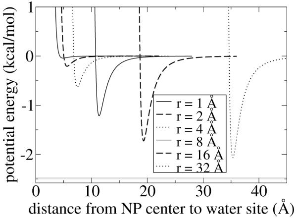
NP-water potential energy for NPs of increasing radius r.
Potential of mean force acting on the NP radius
The potentials derived above for the interaction between the NP and the CG sites in the soft matter portion of the system depend on both d, the distance between the nearest point on the NP and the CG site, and r, the radius of the NP (see Figure 3). By defining a = d + r, we may transform variables from UCG(d,r) to UCG(a,r). This is a manifestation of Gauss’s Law, whereby the interaction potential can be written as if all the NP mass is at the center of the sphere. In terms of a MD simulation, this lets us treat a spherical NP simply as a point particle, even though it is actually an extended solid body.
Let us now discuss the physical significance of ∂UCG/∂a and ∂UCG/∂r. The derivative of the potential with respect to the distance a between the two interacting bodies gives the usual force used in the MD method to displace the bodies in space (i.e. Newton’s second law). This force could thus cause, for example, an organic ligand to collapse onto or be repelled from the NP surface. The derivative of the potential with respect to the sphere radius r gives the force acting on the sphere radius, which would cause the sphere to expand or contract. However, the NP radius is fixed during a MD simulation. Hence this force is not used. Nonetheless, we may calculate its net value, summed over all soft matter particles in the system, and average this quantity over the course of an equilibrium MD simulation. In doing so, we include every term in the force field which depends upon the NP radius. What we obtain is the mean force of constraint, otherwise known as the potential of mean force (PMF), acting on the sphere radius. This quantity forms the basis of a new method to perform free energy calculations. 26
Solvation free energy
First consider a NP, without an organic ligand coating, in a pure solvent. Separately, for different radius NPs, an equilibrium MD simulation can be performed and the PMF acting on the NP radius measured. The PMF can then be integrated as a function of radius, from an initial radius of zero, to obtain , which is the solvation free energy of a NP of radius r. From the definition of surface tension,27 γ ≡ (∂G/∂A)N,P,T, where G is the Gibbs free energy and A is the interfacial area, it follows that γ = G(r)/4π r2. The solvation free energy can be thought of as the free energy cost of “growing” the NP, from a radius of zero to a radius of r, into the solvent. This cost, per unit surface area, is the surface tension. Here the Gibbs dividing surface has been chosen to be the spherical shell of radius r from the center of the NP. More generally, with a Gibbs dividing surface taken as the spherical shell of radius r + σ, the surface tension is γ = G(r)/4π(r + σ)2. This free energy method was introduced by Vázquez26 and shown to be accurate.
Optimal grafting density
Let us now use the PMF method to compute the optimal surfactant chain grafting density for a given surfactant and a given radius NP. Exactly g C12Ex (x=2,5,8) chains are grafted to an intrinsically hydrophobic NP of radius r in water. The graft is implemented by adding a stiff harmonic bond with force constant k = 100 kcal/mol, of equilibrium extension (r + 3 Å), between the NP center and the hydrophobic terminus of the surfactant molecule. This distance corresponds roughly to the van der Waals radius of NP - ligand bead interaction. We retain the non-bonded interactions between the ligand and the NP even though we added a graft since the NP implicitly is comprised of many atoms. The grafting constraint allows the surfactant molecule freedom to diffuse on the surface of the NP. The physical motivation for this diffusion can be rationalized in two ways. On one hand, it mimics the mobile gold-thiol or silver-thiol linkage commonly used in surfactant-NP systems.1 On the other hand, it is a mechanism to allow the surfactant chains to reach equilibrium, which can occur experimentally through ligand exchange of grafted ligands with free molecules in solution.28 The PMF for this system measures the propensity of the NP radius to expand or contract. With no surfactant present, the NP-water interface costs the system energy (in other words the surface tension is positive) and the NP will try to contract. The presence of amphiphilic C12Ex grafted chains will alleviate this contraction force because of the surfactant nature of the ligand. But too high a grafting density will result in steric clashes between chains, causing the NP to want to expand. Our method constrains the ligands to the NP surface, prohibiting them from leaving regardless of whether or not it is favorable to do so. This is of course unphysical, but it is precisely this feature which makes our method powerful: we can sensitively measure when the system is in an unfavorable state. We define the optimal grafting density to be the coverage at which the NP radius experiences a net zero force, namely PMF = 0. Operationally, we fix the number of grafted chains and vary the NP radius in a series of MD simulations to determine the optimal coverage. An example of this procedure is shown in Figure 5 (symbols) for 20 C12E8 chains.
Figure 5.
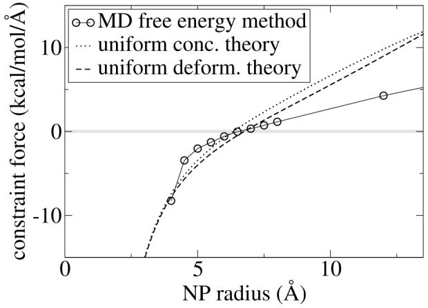
The mean force of constraint on the NP radius (denoted PMF in the text) is plotted against the NP radius for 20 tethered C12E8 chains in water. Notice that all three methods predict roughly the same optimal area per ligand, corresponding to a PMF of zero.
MD details
Simulations were conducted using the MPDyn molecular dynamics software. 29 Each system consists of one nanoparticle, 20, 40, or 100 surfactants (C12E2, C12E5, and C12E8 ), and water, with three-dimensional periodic boundary conditions. The initial coordinates were generated with thesurfactant chains extended straight out from the nanoparticle surface, or by radially expanding or contracting a previous simulation’s coordinates to get the new desired nanoparticle radius. Both types of initial conditions were allowed to equilibrate for a few nanoseconds before collecting data. It is crucial to ensure that enough water is used so that the NP periodic images do not interact. We used the NP-water pair correlation function to monitor this: a box was judged to be sufficiently large if this pair correlation function flattened to unity before the box edge. Oscillations in the solvent density to the box edge indicate that the solvent molecules are ordered by the NP and have not reached their bulk phase behavior. Representative data is shown in Figure 6 for illustrative purposes. Temperature and pressure were controlled using the Nosé-Hoover chain (303.15 K), and the Andersen barostat (0.1 MPa) methods, respectfully. Simulations were run using the reversible RESPA multi-time step method,30 with 0.001 ps for bonded interactions and 0.01 ps for all other interactions, until the PMF value was converged, which generally took less than 10 ns after equilibration. The non-bonded cutoff distance was 15.0 Å for water-water 18 and ligand-water interactions, and (r+20.0 Å) for water-NP and ligand-NP interactions.
Figure 6.
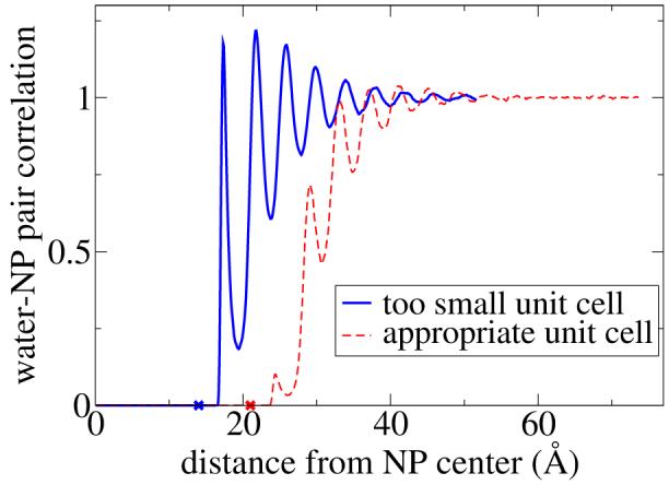
Water-nanoparticle pair correlation function for i) a 14 Å radius NP with 20 C12E8 attached ligands solvated by 12200 water beads (solid line) and ii) a 21 Å radius NP with 100 C12E5 attached ligands solvated by 35500 water beads (dashed line). The NP radii are marked with an X in the figure. Oscillations which persist to the unit cell boundary are indicative of too small a unit cell.
For the flat (infinite radius) simulations, the terminal hydrophobic surfactant bead was tethered to the surface (exactly 3 Å away from the surface) with a harmonic constraint with force constant k = 100 kcal/mol. A water slab of approximately 100 Å thickness was used, and the x-y box size was varied from 60 Å to 110 Å to vary the area per surfactant chain. 50 ns MD simulations were carried out for each system with different areas per surfactant (with the total number of surfactant chains varying between 36 and 100 for different runs), and the optimal coverage was taken to be at the area per chain which gave a surface tension of zero, computed by the conventional pressure tensor method.31
MD Results
To compute the surface area occupied per ligand molecule as a function of the NP radius and of the ligand hydrophilic to lipophilic balance, we used a fixed number of C12Ex chains and varied the NP radius to find the radius corresponding to PMF = 0. Conversely, we could have chosen to fix the NP radius and vary the number of ligand chains. Negative PMF values indicate that the particle is too small for the number of surfactants bound to the surface (or, conversely, that there are too many surfactant chains bound to the particle) and, consequently, the steric interactions between these ligands are unfavorable. On the other hand, positive PMF values indicate that the particle is insufficiently protected from the solvent by the ligand chains because there are too few surfactant molecules bound to the particle. The particle radius at which the PMF is zero is the optimal radius for a given number and type of surfactant. This can be understood as follows: if we integrate the PMF versus radius curve (shown in Figure 5 and Figure 7), which is a procedure known as thermodynamic integration, we obtain the free energy versus radius profile, which exhibits a minimum where the PMF crosses zero. The optimal surface area per ligand chain can then be calculated simply as the surface area of the nanoparticle at its optimal (minimum free energy) radius divided by the the number of chains. We label the optimal radius as r*, and use it to compute the optimal surface area per chain by . The complete MD data set for this study is shown in the vincinity of zero PMF values in Figure 7. This data is used to compute r* and A*, which are shown in Figure 8 along with the flat surface values for A*. In analogy to the method we used to determine A* for spherical NPs, we define A* for ligands attached to a flat surface as the area per chain which results in a surface tension of zero. The physical picture is identical to the spherical NP case: a negative surface tension corresponds to an over-crowded interface in which the surfactant chains have steric overlaps with each other, whereas a positive surface tension corresponds to a situation in which increasing the density of surface-attached chains would lower the free energy of the system. The surface area occupied per ligand, A*, is seen to be strongly dependent on the NP radius. The area per chain increases with increasing NP radius due to increased steric interactions between surfactant chains as the NP curvature decreases. The order of magnitude increase in the optimal coverage area from small radii to a flat surface is consistent with experimental data.6
Figure 7.
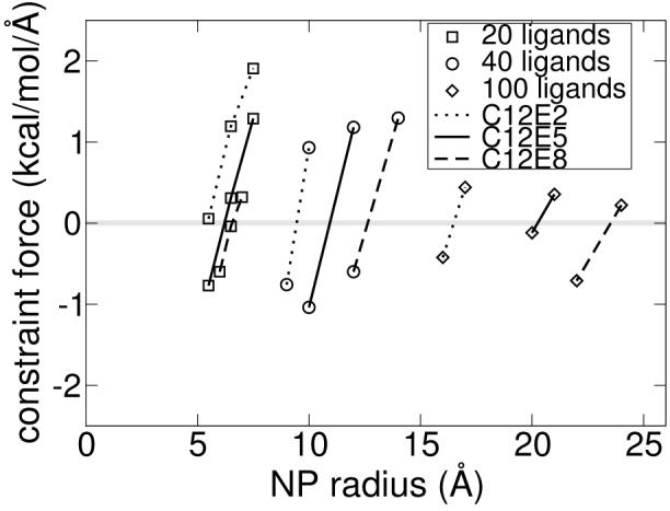
MD simulation data bracketing the optimal NP radius for nine different systems.
Figure 8.
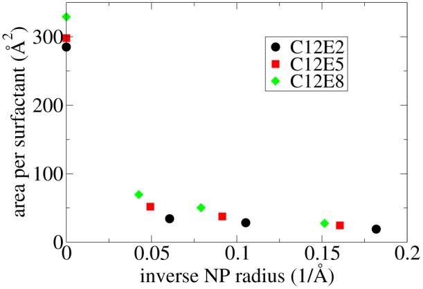
The surface area occupied per ligand chain computed by free energy MD simulations is plotted versus the inverse of the NP radius. The data corresponding to an inverse radius of zero is obtained from simulations of ligands at a flat solid/water interface.
Theoretical Calculations
An independent estimate of the optimal grafting density, based on thermodynamic stabilization, may be obtained by adapting the theory of surfactant self-assembly due to Nagarajan and Ruckenstein to the present context.7 This theory, as applied to the C12Ex non-ionic surfactants with PEO head groups considered above, manifests itself differently depending on whether the head group is treated as compact (x < 6) or as a swollen polymer chain (x > 6). For compact head groups, the theory comprises four free energy terms which are each referenced to the individually dispersed surfactant chains in water, and also to a reference NP state which will be defined below. These terms are: 1) transfer free energy of the surfactant tails into the hydrophobic region of the NP-ligand aggregate; 2) tail deformation free energy; 3) aggregate core-water interfacial free energy; 4) head group steric free energy. For polymer chain head groups, terms 3) and 4) take on a different form, and two additional terms are included: 5) head group-water mixing free energy; 6) head group deformation free energy. Moreover, the polymer chain head group model comes in two limiting flavors in which the head group polymer segments are characterized by having either a uniform concentration or a uniform deformation in the micellar corona region of the aggregate.
We assume that the tails interact with the hydrophobic NP like they interact with themselves, namely that the tails see the NP as a hydrocarbon-like region. Moreover, we assign the reference state for the bare NP to be an aggregated NP phase, for example a NP precipitate in which the NPs have phase separated from water. Term 1) is the only free energy term which is negative, however it is independent of the aggregate size or shape. The remaining terms counterbalance this negative term and determine the optimal size of the NP-ligand aggregate. Details expressions for all the terms are given in the appendix.
Discussion
We now turn out attention to comparing the predictions from MD free energy calculations and from the theoretical model presented above. In Figure 5 we plot the derivative of the free energy (namely the PMF) versus the NP radius for 20 C12E8 chains. The PMF calculated from the molecular dynamics method is almost exactly half of that calculated from the two theoretical approaches for polymer chain head groups. Despite this descrepancy, all three methods yield nearly identical values for r* and hence A*.
For comparison of the A* values for C12E2 and C12E5, we use the compact head group theory. Rather than try to estimate the effective cross-sectional area of the polar head group, we have simply varied the head group size from approximately that of E1 to E12 in the twelve curves shown in Figure 10 (see the Appendix for details). These curves, for larger head group sizes, have the same trend as the MD data, but this agreement requires an unrealistically large head group to be used in the theoretical model.
Figure 10.
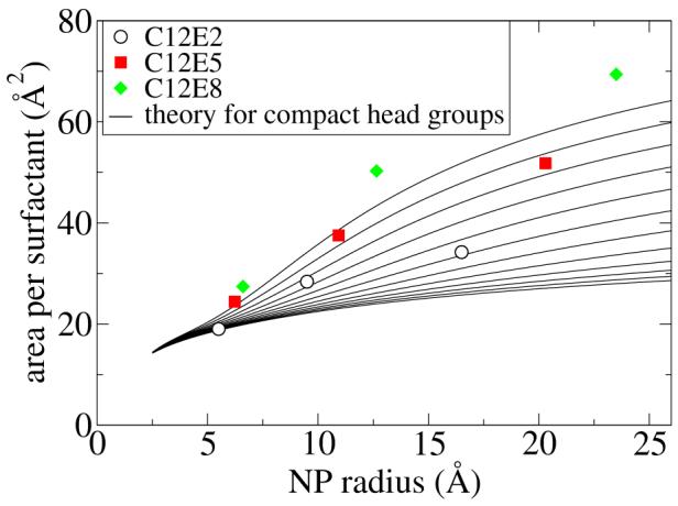
The surface area occupied per ligand chain is plotted versus the NP radius. The MD free energy results are shown with symbols, and the theoretical estimate for compact head groups is shown for C12Ex, with variable x. See the text for details.
For comparison of the A* values for C12E8, we use the polymer chain head group theory, which comes in two limiting cases. As seen in Figure 11, the uniform deformation model is in reasonable agreement with the MD data while the uniform concentration model is not. Analysis of the MD simulations (see Figure 12) clearly shows that the uniform concentration picture does not reflect the PEO chain conformations; instead the PEO concentration gradually decays to zero as a function of distance from the NP, while the corresponding concentation of water increases to its bulk value. This is to be expected. However, we observe a surprising picture closer to the NP surface. Water and PEO head group penetrate to a small extent right up to their closest allowed van der Waals distance from the NP. The reason for this penetration is that the ligand chains tend to cluster instead of spreading out uniformly over the NP surface, whereas an implicit ligand model, or the theoretical model considered here, assume a uniform distribution. A detailed analysis of the non-uniformity is underway but is beyond the scope of the present paper.
Figure 11.
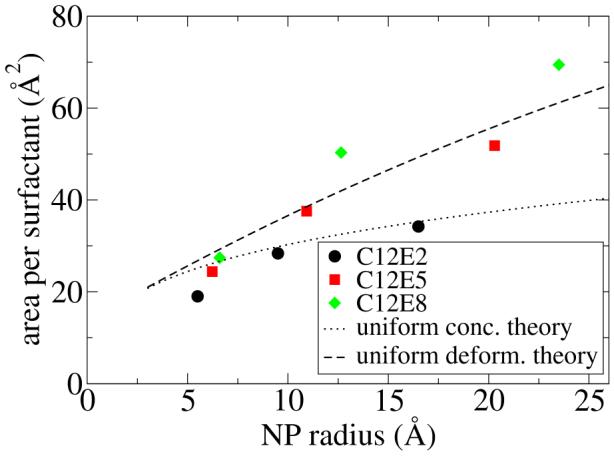
The surface area occupied per ligand chain is plotted versus the NP radius. The MD free energy results are shown with symbols, and the theoretical estimate is shown for C12E8 in two limiting cases.
Figure 12.
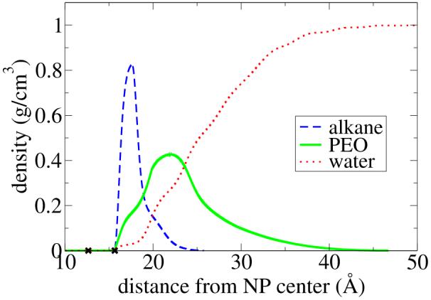
Concentration of the hydrophobic ligand tails (alkane), the polar ligand head group (PEO) and water as a function of distance from the NP for a 12.65 Å radius NP (marked with the first X in the figure) with 40 attached C12E8 chains. The attachment point on the ligand is not included in the density data, but is marked with the second X in the figure at a distance of (r+3 Å) from the NP center.
Conclusions
In this study we presented a detailed analysis of the area per molecule for amphiphilic alkyl poly(oxyethylene) ligands chemisorbed to nanoparticles in aqueous solution, as a function of the hydrophilic to lipophilic balance of the ligand and of the nanoparticle radius. We employed two complementary methods to obtain this information.
First, we introduced a novel coarse grain force field and a novel free energy method to compute the area per molecule using molecular dynamics simulations. The area per molecule which minimizes the free energy of the system achieves a balance between steric clashes among ligand chains at too low an area per molecule and nanoparticle exposure to water at too high an area per molecule. We also computed the area per molecule chemisorbed to a flat solid surface using a surface tension criterion. In agreement with some experimental reports, we showed an order of magnitude increase in the area per molecule chemisorbed to flat surfaces versus nanoparticles. This effect is solely due to the curvature of the solid surface.
Second, we computed the area per molecule by applying the predictive theory of surfactant self-assembly due to Nagarajan and Ruckenstein, which is based on thermodynamic stabilization. These two approaches are only valid for amphiphilic ligands. However, experimental work to control NP organization, whether the goal is crystallization, 1,3 interfacial assembly,12 or colloidal stability,4,32 typically employs amphiphilic ligands.
We then compared and contrasted the two methods. The compact head group model, in which the poly(oxyethylene) polar chain is considered to not be swollen with water but rather form a sharp interface between the alkyl tails and water, is in reasonable agreement with the molecular dynamics data if we use a larger cross-sectional head group area than would seem appropriate from the molecular structure. The polymer chain head group model, in which the poly(oxyethylene) polar chain is considered to be swollen with water, is in poor agreement with the molecular dynamics data in the uniform concentration limit, and in reasonable agreement with the molecular dynamics data in the uniform deformation limit. A uniform head group concentration is only possible if the poly(oxyethylene) chains deform nonuniformly along the nanoparticle radial coordinate, whereas a uniform head group deformation along this coordinate allows for a water concentration gradient as one approaches the alkane core. Analysis of the molecular dynamics data clearly shows such a concentration gradient, but water and poly(oxyethylene) units are even seen to penetrate (with low probability) to the nanoparticle surface, which is not considered in the theory. The reason for this penetration is that the ligand chains tend to cluster instead of spreading out uniformly over the nanoparticle surface. A detailed analysis of the non-uniformity is in progress.
The area per molecule computed here may be considered as the optimal coverage of nanoparticles by ligands in the sense it minimizes the free energy of the system. Normally in the literature optimal coverage is defined to be the ligand coverage which prevents particle aggregation - in other words the ligand coverage which imparts colloidal stability. 33,34 It would be interesting to explore the relationship between these two optimal coverages.
Acknowledgement
The authors gratefully acknowledge discussions with Dr. Ramanathan Nagarajan (Nagu) on the implementation of his theory. The authors acknowledge the Donors of the American Chemical Society Petroleum Research Fund for partial support of this research. Dr. Moore would like to acknowledge that this research was supported in part by a gift from the H.O. West Foundation, a grant from the University of the Sciences in Philadelphia (USP), a grant from the National Institute of Health (1R15GM075990-01), and grants from the National Science Foundation (CHE-0420556 and CCF-0622162). The authors would also like to acknowledge the Texas Advanced Computing Center (TACC) at The University of Texas at Austin for providing HPC resources that have contributed to the research results reported within this paper.
Appendix: theoretical details
Here we give the details concerning the theoretical model of Nagarajan and Ruckenstein, 7 as adapted for the present context. The free energy as function of g surfactant chains is expressed as a sum of terms
| (4) |
where N = 4 for the compact head group model and N = 6 for the polymer chain head group model.
Term 1) is computed from experimental transfer free energy values from water to oil. For g surfactant chains each with 11 methylene and 1 methyl group in the tail, the transfer free energy is
| (5) |
For term 2), the surfactant tails must satisfy three constraints: i) one end of the tail is tethered to the NP surface and hence lies a distance RNP = r from the NP center (see Figure 9); ii) the other end of the tail is located at the hydrophobic/hydrophilic boundary, a distance Rs from the NP center; iii) the density in the hydrophobic shell region is 0.74 g/mL, namely the bulk density of dodecane at 300 K. These three constraints are met by adapting the uniform concentration head group deformation free energy expression from Nagarajan by assigning the inner radius as RNP, the shell thickness as Rs - RNP, and by using 11 methylene and 1 methyl group to compute the tail segment volume fraction, yielding
| (6) |
Here is the area per surfactant molecule at the hydrophobic/hydrophilic interface, and Rs is simply determined from the requirement that the C12 contains g dodecane molecules at their bulk hydrocarbon density. In addition, ϕ is the volume fraction of alkane segments, given by ϕ = gNL3/V where , N = 3.61 is the number of segments in dodecane, and L = 4.6 Å is the linear dimension of an alkane segment. For the surfactant tails, Eq. (6) thus becomes with for radii measured in Angstroms.
Figure 9.
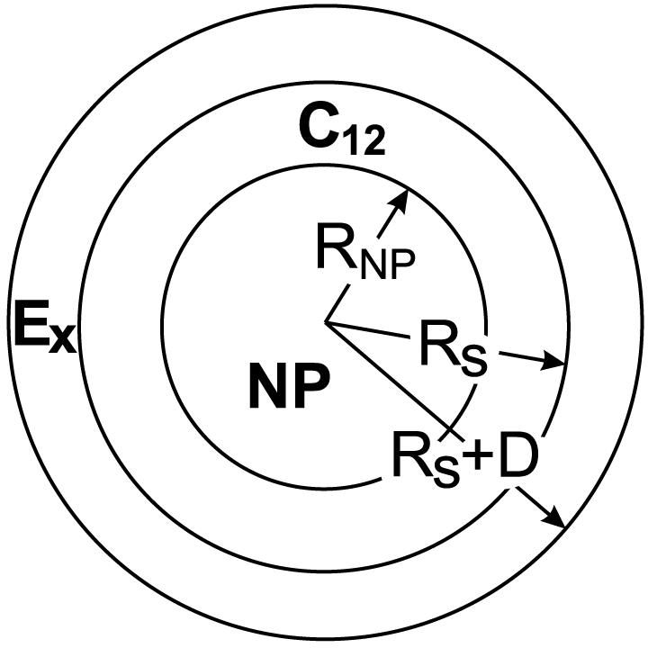
Schematic geometry for the theoretical grafting density estimate
Term 3) is given by the product of the area of the interface and the interfacial tension, σagg, of the aggregate core-water interface,
| (7) |
For the compact head group model, σagg = σsw = 50.3 dyn/cm, the interfacial tension between the surfactant alkane tails and water (shielding by the head groups is accounted for with the a0 term). In addition, a0 = L2 where L = 4.6 Å is the linear dimension of an alkane segment. For the polymer chain head group model, where νE = 63 Å3 is the volume of an oxyethylene unit at room temperature. Also, σagg, the tension between the hydrophobic region and aqueous PEO region, is calculated using Prigogine’s theory for the surface tension of solutions and is different in the uniform concentration versus uniform deformation model for the PEO chains.
Term 4) is given by
| (8) |
where ap is the effective cross-sectional area of the polar head group near the core surface. For the compact head group model, we take ap = (xνE)2/3 with x = 1,2,3,..., 12 (see Figure 10). For the polymer chain head group model we take .
Term 5) is given by either
| (9) |
where ϕEg is the PEO segment density in the corona region under the uniform concentration model, or by
| (10) |
where ϕR is the head group segment density under the uniform deformation model, which depends on the distance between the segment and the NP. In these expressions D is the thickness of the head group corona region (see Figure 9), NE is the number of PEO segments, and χwE = 0.1 is the Flory-Huggins interaction parameter for the water-poly(oxyethylene) mixture. Using the appropriate expressions for ϕEg and ϕR, we obtain
for the uniform concentration model and
for the uniform deformation model, where Ex is the number of PEO monomers in the head group. Term 6) is similar to term 2), yielding
| (11) |
for the uniform concentration model and
| (12) |
for the uniform deformation model.
The shell thickness D is a free parameter: it must be chosen to minimize the overall free energy of the system. Operationally, we fix the number of grafted chains g and vary the NP radius to determine the radius which minimizes the free energy. To compare with the PMF from the MD method, we take the numerical derivative, with respect to the NP radius, of the free energy versus NP radius plot.
We should point out that the terms discussed above assume a reference state where the surfactant molecules are individually dispersed in water. If we changed the reference state, for example by assuming that the surfactants are present in micelles which are in equilibrium with the ligand-coated NP, the predictions from the theory would change. However, the PMF method has no such reference state because if a ligand detached from the NP, it would fall outside of the interaction range with the NP, resulting in a force of zero between the ligand and the NP. Whether this detached ligand ended up individually dispersed in water or in a micelle, there would be no difference in the measured (PMF) free energy.
Notes and References
- (1).Kalsin AM, Fialkowski M, Paszewski M, Smoukov SK, Bishop KJM, Grzybowski BA. Science. 2006;312:420. doi: 10.1126/science.1125124. [DOI] [PubMed] [Google Scholar]
- (2).Pradeep T, Sandhyarani N. Pure Appl. Chem. 2002;74:1593. [Google Scholar]
- (3).Shevchenko EV, Talapin DV, Kotov NA, OBrien S, Murray BC. Nature. 2006;439:55. doi: 10.1038/nature04414. [DOI] [PubMed] [Google Scholar]
- (4).Dubertret B, Skourides P, Norris DJ, Noireaux V, Brivanlou AH, Libchaber A. Science. 2002;298:1759. doi: 10.1126/science.1077194. [DOI] [PubMed] [Google Scholar]
- (5).Jadzinsky PD, Calero G, Ackerson CJ, Bushnell DA, Kornberg RD. Science. 2007;318:430. doi: 10.1126/science.1148624. [DOI] [PubMed] [Google Scholar]
- (6).Corbierre MK, Cameron NS, Lennox RB. Langmuir. 2004;20:2867. doi: 10.1021/la0355702. [DOI] [PubMed] [Google Scholar]
- (7).Nagarajan R, Ruckenstein E. Langmuir. 1991;7:2934. [Google Scholar]
- (8).Luedtke WD, Landman U. J. Phys. Chem. 1996;100:13323. [Google Scholar]
- (9).Ghorai PK, Glotzer SC. J. Phys. Chem. C. 2007;111:15857. [Google Scholar]
- (10).Kim BJ, Fredrickson GH, Kramer EJ. Macromolecules. 2008;41:436. [Google Scholar]
- (11).Patel N, Egorov SA. J. Chem. Phys. 2007;126:054706. doi: 10.1063/1.2434155. [DOI] [PubMed] [Google Scholar]
- (12).Glogowski E, Tangirala R, He J, Russell TP, Emrick T. Nano Lett. 2007;7:389. doi: 10.1021/nl062581h. [DOI] [PubMed] [Google Scholar]
- (13).Russel WB, Saville DA, Schowalter WR. Colloidal Dispersions. Cambridge University Press; Cambridge: 1989. [Google Scholar]
- (14).Mueller M, Katsov K, Schick M. Phys. Rep. 2006;434:113. [Google Scholar]
- (15).Ortiz V, Nielsen SO, Klein ML, Discher DE. J. Polym. Sci. Part B: Polym. Phys. 2006;44:1907. [Google Scholar]
- (16).Nielsen SO, Lopez CF, Srinivas G, Klein ML. J. Phys.: Condens. Matter. 2004;16:R481. [Google Scholar]
- (17).When there is more than one NP present, the resultant B-B interactions are included in the second class.
- (18).Shinoda W, DeVane R, Klein ML. Mol. Sim. 2007;33:27. [Google Scholar]
- (19).Shinoda W, DeVane R, Klein ML. Soft Matter. 2008;4:2454. [Google Scholar]
- (20).MacKerell AD, et al. J. Phys. Chem. B. 1998;102:3586. doi: 10.1021/jp973084f. [DOI] [PubMed] [Google Scholar]
- (21).Lee SH, Rossky PJ. J. Chem. Phys. 1994;100:3334. [Google Scholar]
- (22).Nielsen SO, Srinivas G, Lopez CF, Klein ML. Phys. Rev. Lett. 2005;94:228301. doi: 10.1103/PhysRevLett.94.228301. [DOI] [PubMed] [Google Scholar]
- (23).Shelley JC, Patey GN. Mol. Phys. 1996;88:385. [Google Scholar]
- (24).Hamaker HC. Physica. 1937;4:1058. [Google Scholar]
- (25).Hammersley JM, Handscomb DC. Monte Carlo Methods. Chapman and Hall; London: 1964. [Google Scholar]
- (26).Vázquez UOM, Shinoda W, Moore PB, Chiu C, Nielsen SO. J. Math. Chem. 2008 DOI: 10.1007/s10910-008-9374-7. [Google Scholar]
- (27).Moore WJ. Physical Chemistry. 4th ed. Prentice-Hall; New Jersey: 1972. [Google Scholar]
- (28).Jackson AM, Myerson JW, Stellacci F. Nature Mater. 2004;3:330. doi: 10.1038/nmat1116. [DOI] [PubMed] [Google Scholar]
- (29).Shinoda W, Mikami M. J. Comput. Chem. 2003;24:920. doi: 10.1002/jcc.10249. [DOI] [PubMed] [Google Scholar]
- (30).Tuckerman ME, Berne BJ, Martyna GJ. J. Chem. Phys. 1992;97:1990. [Google Scholar]
- (31).Zhang YH, Feller SE, Brooks BR, Pastor RW. J. Chem. Phys. 1995;103:10252. [Google Scholar]
- (32).Yin Y, Alivisatos AP. Nature. 2005;437:664. doi: 10.1038/nature04165. [DOI] [PubMed] [Google Scholar]
- (33).Gast AP, Leibler L. Macromolecules. 1986;19:686. [Google Scholar]
- (34).Brittain WJ, Minko S. J. Polym. Sci. Part A: Polym. Chem. 2007;45:3505. [Google Scholar]


