Abstract
Extracellular matrix (ECM) provides a dynamic three-dimensional structure which translates mechanical stimuli to cells. This local mechanical stimulation may direct biological function including tissue development. Theories describing the role of mechanical regulators hypothesize the cellular response to variations in the external mechanical forces on the ECM. The exact ECM mechanical stimulation required to generate a specific pattern of localized cellular displacement is still unknown. The cell to tissue inverse problem offers an alternative approach to clarify this relationship. Developed for structural dynamics, the inverse dynamics problem translates measurements of local state variables (at the cell level) into an unknown or desired forcing function (at the tissue or ECM level). This paper describes the use of eigenvalues (resonant frequencies), eigenvectors (mode shapes), and dynamic programming to reduce the mathematical order of a simplified cell–tissue system and estimate the ECM mechanical stimulation required for a specified cellular mechanical environment. Finite element and inverse numerical analyses were performed on a simple two-dimensional model to ascertain the effects of weighting parameters and a reduction of analytical modes leading toward a solution. Simulation results indicate that the reduced number of mechanical modes (from 30 to 14 to 7) can adequately reproduce an unknown force time history on an ECM boundary. A representative comparison between cell to tissue (inverse) and tissue to cell (boundary value) modeling illustrates the multiscale applicability of the inverse model.
Keywords: Cell biomechanics, Extracellular matrix, Mechanotransduction, Dynamic programming, Finite element analysis, Eigenvalue reduction, Inverse problem
1. Introduction
Living cells are constantly subjected to mechanical stimulations. These stresses and strains can arise from both external environmental and internal physiological conditions (Lim et al., 2006). Mechanobiology explores the essential connections between forces acting within tissues, cells, and individual molecules, and the fundamental biological processes that regulate growth, development, cell differentiation, and apoptosis. Unfortunately, there is no consensus as to the mechanism in which the mechanical signals generated at the tissue-level are optimally effective in modulating cell function.
Single-cell biomechanics studies offer a focused approach to identify the factors which influence cellular biological responses without the added complexity of cell–ECM interactions. Several methods directly manipulate the mechanical environment of individual cells (Shieh and Athanasiou, 2003; Bao and Suresh, 2003). Micropipette aspiration has been applied to numerous cell types (Hochmuth, 2000; Haider and Guilak, 2002; Trickey et al., 2000). Atomic force microscopy with its cantilevered beam and nanometer-scale tip can probe local regions of a cell (Ricci et al., 1997; Bader et al., 2002; Gianoli et al., 2001) or facilitate microscale indentation of an entire cell (Koay et al., 2003; Leipzig and Athanasiou, 2005). The μPIVOT was recently developed to apply multiaxial stresses to single cells suspended with optical tweezers (Nève et al., 2008; Kohles et al., 2008). With these techniques the cell-level stress–strain environment may be characterized for mechanotransduction hypothesis testing. However, developing regenerative therapies from these results requires translating cell-level manipulations to tissue-level forces (Kohles et al., 2007b).
This paper describes an inverse mathematical method to translate cell-level mechanical stresses to tissue-level mechanical forces in order to determine the tissue-level external forces required to generate the cellular perturbations within single-cell biomechanics studies. The resulting tissue-level stress–strain environment can be compared with known multiaxial joint loads to identify ‘physically realistic’ single-cell loading regimes. More importantly, the method can predict the tissue-level mechanical stimulation required to induce experimentally identified single-cell regenerative or degenerative processes. The mathematical method applies modal analysis with dynamic programming to estimate the external forces on an ECM region from internal cellular node input.
2. Methods
2.1. The inverse problem
The inverse method has been explored extensively in the realm of heat transfer (Busby and Trujillo, 1985). Structural dynamics or vibrations applications have employed inverse modeling or examined identification problems (Simonian, 1981a, b). The inverse problem may be more difficult to solve than the direct boundary value problem, as many inverse relationships are not directly defined or are ill-posed. In most inverse problems, the local perturbation is known or prescribed and either the equations describing the process are unknown (a modeling or identification problem) (Kim et al., 1993, 1994; Kim and Voloshin, 1995) or the external environment is unknown (the inverse problem).
The biomechanical system of interest can be expressed as a matrix differential equation of motion with initial conditions c (at t = 0)
| (1) |
where K is an (n×n) internal system matrix, T is (n×ng) external application matrix, x is an (n×1) vector representing the state variables and g is an (ng×1) vector representing the applied forcing variables. The most common biomechanical problem models the direct solution. For that approach, the system matrix K is known, the external forcing arrangement Tg is known, and the unknown state variables x(t) are found by integrating Eq. (1) based on known initial conditions. The inverse problem, however, is one in which the system matrix K is known together with information on some or all of the state variables (such as ECM and cell properties), however, the forcing function term g is unknown. Thus, given the system matrix K and measurements of the state variables as input, the forcing term g must be found to provide a model which best relates the external load applications with the internal measurements.
The differential Eq. (1) is integrated as an equivalent time discrete model assuming an exponential matrix. This yields the finite difference equation
| (2) |
where M and P are the dynamic transformation matrices, for K and T, respectively. Applying a step size h and the identity matrix I, the transformation matrices are defined as
| (3) |
Thus, the initial analytical premise converts to a discrete approach with N total stages or time steps. A simple expression that relates the modeled variables xj to the corresponding modeled displacements zj for comparison with the measured displacements dj is
| (4) |
where Q is an (nz×n) matrix. This converts the model variables into a (nz×1) vector zj. The vector dj and zj can be compared with a least square error expression
| (5) |
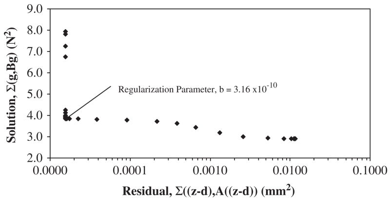
where vectors separated by a comma denote an inner product. Here, A(nz×nz) and B(ng×ng) are weighting matrices to help smooth the forcing functions, such that A is an identity matrix and B is a diagonal matrix. The addition of the term (gj, Bgj) is a regularization component for numerical smoothing and accuracy control, known as the Tikhonov’s method (Tikhonov and Arsenin, 1977). The optimal value of B is estimated by either generalized cross validation (Trujillo and Busby, 1997) or the Tikhonov L-curve method, proposed by Hansen (1992). The L-curve provides information about the regularized solution by plotting the iterative solution of Eq. (5) versus the residual vectors (the deviation between observed and predicted values) typically on logarithmic axes. In this simplified application, a scalar of the regularization parameter b was chosen by association with the characteristic reflection point on the plot.
The approach identifies the applied forcing function gj which drives the modeled properties xj to match the input displacement data dj as closely as possible. Thus, the problem reduces to minimizing the function EN starting at any stage or time step with an initial value c, simulating the system to the Nth iteration (j = N) over a sequence of forcing vectors gj, i.e., .
2.2. Cell–ECM application and modal analysis
The application of the described model represents a second-order differential equation of motion characterizing the dynamic response to mechanical loading
| (6) |
where M is the diagonal mass matrix, K is the stiffness matrix, L is the load location matrix, f represents the applied forcing variables, u is the responding elastic displacement vector, and ü is the rigid body acceleration vector. This model is converted to a first-order system equation by defining
| (7) |
In matrix form, Eq. (6) becomes
| (8) |
An eigenvalue analysis is then performed to determine the roots of the characteristic equation. Each distinct modal vector component ϕi and natural frequency ωi are set to satisfy the following relationships:
| (9) |
| (10) |
| (11) |
where the orthogonal conditions (Kϕi, ϕj) = 0 and (Mϕi, ϕj) = 0, are satisfied for i ≠ j. The modal frequency component was expressed in matrix form by making each diagonal mass term equal to 1.0, where
| (12) |
and
| (13) |
The original system is then transformed into a modal analysis arrangement with the relationship
| (14) |
where z is a (n×1) position vector and zi can be represented as a weighting factor within a linear combination of modal components such that u = z1ϕ1+z2ϕ2+z3ϕ3+…+znϕn. Substituting Eq. (14) into Eq. (6) gives
| (15) |
Multiplying Eq. (15) by ϕT and applying Eq. (13) resulted in the decoupled matrix equations
| (16) |
Thus the modal components reduce the order of the system where specific modes are selected to approximate u from Eq. (6). The selection of a small number of mechanical modes m to approximate the state variables referred to in Section 2.1 are represented as
| (17) |
where the S (n×m) matrix contains the selected mechanical modes by each node and p is a (m×1) vector representing the number of m modes. Combining Eqs. (14) and (17) yields a modified Eq. (16)
| (18) |
Similar to Eq. (7), this system is converted into a set of first-order equations where:
| (19) |
These equations are then converted into a discrete difference form as noted in Eq. (2) for application to the simplified cell–ECM model via the dynamic programming approach.
2.3. Numerical simulation and validation
Three analyses were conducted to ascertain how the reduced analytic model would perform. A two-dimensional finite element model was first used to generate multiple displacement time histories associated with a specified force history. Of these time histories, one was selected and used as input data to the dynamic programming approach just described. A cartilage tissue sample region comprised of ‘ECM’ elements and ‘cell’ nodes was modeled as isotropic and homogenous with the following properties: Young’s modulus, E = 1.0 MPa; Poisson’s ratio, ν = 0.125; and density, ρ = 10−7 kg/mm3 (Guilak and Mow, 2000).
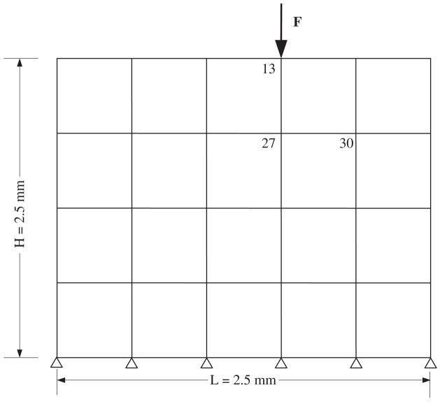
Commercially available finite element analysis (FEA) software (v11, ANSYS, Inc., Canonsburg, PA) was used to perform a two-dimensional plane-strain analysis of the ECM region thus generating the mass M and stiffness matrix K in Eq. (8) (Fig. 1). The FEA model contained 20 elements each with four nodes (2D PLNAE42 element, ANSYS Library) and a total of 30 degrees of freedom (DOF) (two DOF per unconstrained element). Only the displacements indicated at nodes 27 and 30 were used for the inverse solution when determining the unknown external load.
Fig. 1.
The cell–ECM numerical model with key node numbers noted. The model illustrates the macroscopic ‘tissue’ level in which chondrocytes are assumed to be embedded at node locations. An external force, F, was applied at node 13. Two displacement output measurement locations were identified at nodes 27 and 30. The mass and stiffness system matrices (Eq. (8)) produced from this finite element analyses were used as input for the inverse solution.
The FEA modal analysis produced the roots of the characteristic equation (eigenvalues) and the mechanical mode shape (eigenvectors) as the required input (Table 1) for the mathematical solver that characterized the state space model (MATLAB, Mathworks, Inc., Natick, MA). ANSYS eigenvalue and eigenvector results were converted to MATLAB input form using open-source code (Hatch, 2001). The inverse analysis addressed the prediction of a single aperiodic load applied at node 13 using two hypothetical cell displacement measurements taken at nodes 27 and 30 (Fig. 1). The FEA and inverse models were compared for a ramped forcing function scenario having a peak force of 0.5N and a pulse width of 0.75 s. This mechanical regime represents a maximum normal compressive stress of 150 Pa associated with a controlled hydrodynamic microenvironment designed for single-cell biomechanics (Kohles et al., 2009). An integration time step of 0.004 s was used for a total of 27 steps in both analyses.
Table 1.
The seven vibrational modes and their corresponding eigenvalues and natural frequencies (ωi) used in Eq. (11).
| Vibration mode (m) | Eigenvalue (Hz) | Natural frequency, ωi (rad/s) |
|---|---|---|
| 1 | 0.0 | 0.0 |
| 2 | 190.4 | 1196.0 |
| 3 | 398.5 | 2503.8 |
| 4 | 468.7 | 2944.9 |
| 5 | 599.2 | 3764.8 |
| 6 | 715.6 | 4496.4 |
| 7 | 818.3 | 5141.5 |
Case 1 values are listed here. Note that Mode 1 represents the rigid body response (which was constrained).
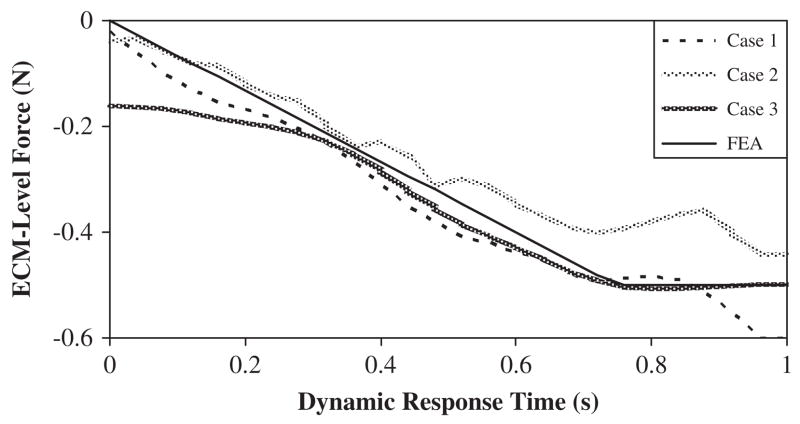
To demonstrate the dynamic features of the eigenvalue and eigenvector method: Case 1 applied the reduced system equations resulting in the first seven mechanical vibration modes produced at node 27; Case 2 examined the first fourteen vibration modes; while Case 3 included all 30 modes.
As an applied example, the forces and resulting strains during single-cell compression experiments (Koay et al., 2008) provided input values for the inverse model, determining the hypothetical tissue level forces (cell to tissue). Comparatively, resultant shoulder joint peak loads averaged from all subjects in a recent rehabilitation study (Kohles et al., 2007a) provided the mechanical input for a boundary value calculation of the mechanics hypothetically experienced at the cell level (tissue to cell).
3. Results
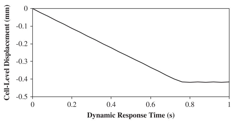
The corresponding eigenvalues and eigenvectors were determined via the FEA model as input for the reduced system of equations (inverse approach). The displacement histories of node 30 were constrained to be similar by design in all Cases (Fig. 2). The predicted dynamic applied forces resulting from the three inverse analyses Cases were compared with the FEA modeled applied force (Fig. 3). The Case 1 inverse solution overestimated the final modeled ramp force by 20% at t = 1 s (0.60N vs. 0.50 N). In Case 2, the number of incorporated modes increased two-fold, thus causing the inverse solution to be more oscillatory. However, the final value of the inversely solved ramped force under-estimated the FEA produced value by 14% at t = 1 s (0.43N vs. 0.50 N). Overall, the improvement in predicting the magnitude of the applied force was increased by 6% when doubling the number of modes in the solution process. When incorporating the full modal response (Case 3), the inverse solution initiated with non-zero values then proceeded to form a solution more similar to the FEA final value. Upon post-processing, the Tikhonov L-curve for Case 1 indicated a distinct ‘corner’ which was associated with the optimized value of the regularization parameter b (here B was set to a scalar due to the presence of a single force vector). Thus, the smoothing parameter for this approach was associated with the flexion point on the logarithmic plot of the iterative solutions versus the residuals and was chosen as b = 3.16×10⁻¹⁰ (Fig. 4). An example calculation using the simplified node arrangement and assumed linear elastic behavior, provides a direct comparison between the presented inverse model and traditional boundary value models (Table 2).
Fig. 2.
Model displacement produced by the finite element analysis as output and applied to the inverse solution as input. The curve was generated at node 27.
Fig. 3.
Predicted applied forces at node 13, framed as a mechanical input based on a known displacement at node 27 representing 7 (Case 1), 14 (Case 2) and 30 (Case 3) vibrational response mode shapes.
Fig. 4.
The Tikhonov L-curve for Case 1. A distinct ‘corner’ in the plot was associated with the regularization parameter b, optimized through analytical iteration.
Table 2.
A comparative example demonstrating the results of both the inverse and boundary value models.
| Cell-level | Model approach | Tissue-level | Elastic modulus (E) |
|---|---|---|---|
| Experiment: 100 nN (50% strain) | Inverse | Model: 2.0 N | 1 MPa |

|
20.0 N | 10 MPa | |
| Model: 84 nN (46% strain) | Boundary Value | Experiment: 92.8 N | 100 MPa |

|
Cell level (Koay et al., 2008) and tissue level (Kohles et al., 2007a) experiments provided mechanical input parameters for representative calculations. Modulus values were adjusted to account for the differing rates of loading in the two scenarios (Unsworth, 1981).
4. Discussion
The analytic approach produces reasonably accurate results even for a reduced number of vibrational response modes over few measurement locations or nodes. This analytical approach may be applicable to tissue engineering, where strategies to improve and/or accelerate tissue regeneration involve multivariate formulations within extracellular microenvironments that influence specific growth-inductive signals (Pizzo et al., 2005). The approach here uses a vibrational modal analysis (not the actual vibrational response) as a means to create multiscale relationships. The inverse model, through the described reduction mechanism, can be used to examine how ECM provides a three-dimensional support network for a geometric cellular distribution with minimal necessary degrees of freedom. Previous cell-level models have included thousands of degrees of freedom (Guilak and Mow, 2000). In the inverse approach, multiple possible external mechanical solutions may contribute to similar internal cell biomechanics. Resulting external mechanical conditions can be judged ‘unique’ by comparison with known in vivo human joint and tissue loads as shown here from normal, i.e., healthy, function (Kohles et al., 2007a).
Acknowledgments
Numerical modeling resources were facilitated by Drs. Sung Yi and Hormoz Zareh. This analytical work supports the ongoing research effort funded by the NSF (CBET-0521637), the NIH (EB007077 and MD003350), and the Collins Medical Trust.
Footnotes
Conflict of Interest Statement
The material presented here is not connected with any entity that would inappropriately influence or bias this work, thus the authors have no conflict of interest.
Publisher's Disclaimer: This article appeared in a journal published by Elsevier. The attached copy is furnished to the author for internal non-commercial research and education use, including for instruction at the authors institution and sharing with colleagues.
Other uses, including reproduction and distribution, or selling or licensing copies, or posting to personal, institutional or third party websites are prohibited.
In most cases authors are permitted to post their version of the article (e.g. in Word or Tex form) to their personal website or institutional repository. Authors requiring further information regarding Elsevier's archiving and manuscript policies are encouraged to visit: http://www.elsevier.com/copyright
References
- Bader DL, Ohashi T, Knight MM, Lee DA, Sato M. Deformation properties of articular chondrocytes: a critique of three separate techniques. Biorheology. 2002;39(1–2):69–78. [PubMed] [Google Scholar]
- Bao G, Suresh S. Cell and molecular mechanics of biological materials. Nature Materials. 2003;2(11):715–725. doi: 10.1038/nmat1001. [DOI] [PubMed] [Google Scholar]
- Busby HR, Trujillo DM. Numerical solution to a two-dimensional inverse heat conduction problem. International journal of Numerical Method Engineering. 1985;21:349–359. [Google Scholar]
- Gianoli DJ, Kohles SS, Burnham NA, Clark MB, Brown CA, Kenealy JN. The feasibility of atomic force microscopy as a cytodetachment technique to quantify osteoblastic adhesion with implant surfaces. In: Enderle JD, Macfarlane LL, editors. Proceedings of the IEEE Twenty Seventh Northeast Bioengineering Conference; 2001. pp. 5–6. [Google Scholar]
- Guilak F, Mow VC. The mechanical environment of the chondrocyte: a biphasic finite element model of cell–matrix interactions in articular cartilage. Journal of Biomechanics. 2000;33:1663–1673. [PubMed] [Google Scholar]
- Haider MA, Guilak F. An axisymmetric boundary integral model for assessing elastic cell properties in the micropipette aspiration contact problem. Journal of Biomechanical Engineering. 2002;124(5):586–595. doi: 10.1115/1.1504444. [DOI] [PubMed] [Google Scholar]
- Hansen PC. Analysis of discrete ill-posed problems by means of the L-curve. SIAM Review. 1992;34(4):561–580. [Google Scholar]
- Hatch MR. Vibration Simulation Using MATLAB and ANSYS. Chapman & Hall; Boca Raton: 2001. [Google Scholar]
- Hochmuth RM. Micropipette aspiration of living cells. Journal of Biomechanics. 2000;33(1):15–22. doi: 10.1016/s0021-9290(99)00175-x. [DOI] [PubMed] [Google Scholar]
- Kim W, Voloshin AS. Role of Plantar Facia in the load bearing capacity of the human foot. Journal of Biomechanics. 1995;28(9):1025–1033. doi: 10.1016/0021-9290(94)00163-x. [DOI] [PubMed] [Google Scholar]
- Kim W, Voloshin AS, Johnson SH. Measurement of the impulsive bone motion by skin-mounted accelerometers. Journal of Biomechanical Engineering. 1993;115:47–52. doi: 10.1115/1.2895470. [DOI] [PubMed] [Google Scholar]
- Kim W, Voloshin AS, Johnson SH. Modeling of heel strike transients during running. Human Movement Science. 1994;13:221–244. [Google Scholar]
- Koay EJ, Shieh AC, Athanasiou KA. Creep indentation of single cells. Journal of Biomechanical Engineering. 2003;125(3):334–341. doi: 10.1115/1.1572517. [DOI] [PubMed] [Google Scholar]
- Koay EJ, Ofek G, Athanasiou KA. Effects of TGF-beta1 and IGF-I on the compressibility, biomechanics and strain-dependent recovery behavior of single chondrocytes. Journal of Biomechanics. 2008;41(5):1044–1052. doi: 10.1016/j.jbiomech.2007.12.006. [DOI] [PubMed] [Google Scholar]
- Kohles SS, Gregorczyk KN, Phillips TC, Brody LT, Orwin JF, Vanderby R., Jr Concentric and eccentric shoulder rehabilitation biomechanics. Journal of Engineering in Medicine: Proceedings of the Institution of Mechanical Engineers Part H. 2007a;221(3):237–249. doi: 10.1243/09544119JEIM140. [DOI] [PubMed] [Google Scholar]
- Kohles SS, Wilson CG, Bonassar LJ. A mechanical composite spheres analysis of engineered cartilage dynamics. Journal of Biomechanical Engineering. 2007b;129:473–480. doi: 10.1115/1.2746366. [DOI] [PMC free article] [PubMed] [Google Scholar]
- Kohles SS, Nève N, Lingwood JK, Zimmerman JD, Winn SR, Zelick RD, Tretheway DC. An Integrated Optical Instrument and Microfluidics for Isolated Chondrocyte, Osteoblast, and Fibroblast Biomechanics. Transactions of the Fifty Fourth Annual Meeting; 2008. ORS, paper# 1168. [Google Scholar]
- Kohles SS, Nève N, Zimmerman JD, Tretheway DC. Local Variation in Surface Stresses Applied to Suspended Single Cells in Microfluidic Environments. Transactions of the Fifty Fifth Annual Meeting; 2009. ORS, paper# 1231. [Google Scholar]
- Leipzig ND, Athanasiou KA. Unconfined creep compression of chondrocytes. Journal of Biomechanics. 2005;38(1):77–85. doi: 10.1016/j.jbiomech.2004.03.013. [DOI] [PubMed] [Google Scholar]
- Lim CT, Zhou EH, Quek ST. Mechanical models for living cells—a review. Journal of Biomechanics. 2006;39(2):195–216. doi: 10.1016/j.jbiomech.2004.12.008. [DOI] [PubMed] [Google Scholar]
- Nève N, Lingwood JK, Zimmerman J, Kohles SS, Tretheway DC. The μPIVOT: an integrated particle image velocimeter and optical tweezers instrument for microenvironment investigations. Measurement Science and Technology. 2008;19(9):095403. doi: 10.1088/0957-0233/19/9/095403. [DOI] [PMC free article] [PubMed] [Google Scholar]
- Pizzo AM, Kokini K, Vaughn LC, Waisner BZ, Voytik-Harbin SL. Extracellular matrix (ECM) microstructural composition regulates local cell–ECM biomechanics and fundamental fibroblast behavior: a mutidimensional perspective. Journal of Applied Physiology. 2005;98:1909–1921. doi: 10.1152/japplphysiol.01137.2004. [DOI] [PubMed] [Google Scholar]
- Ricci D, Tedesco M, Grattarola M. Mechanical and morphological properties of living 3T6 cells probed via scanning force microscopy. Microscopy Research & Technique. 1997;36:165–171. doi: 10.1002/(SICI)1097-0029(19970201)36:3<165::AID-JEMT4>3.0.CO;2-O. [DOI] [PubMed] [Google Scholar]
- Shieh AC, Athanasiou KA. Principles of cell mechanics for cartilage tissue engineering. Annals of Biomedical Engineering. 2003;31(1):1–11. doi: 10.1114/1.1535415. [DOI] [PubMed] [Google Scholar]
- Simonian SS. Inverse problems in structural dynamics—I. Theory. International Journal of Numerical Method Engineering. 1981a;17:357–365. [Google Scholar]
- Simonian SS. Inverse problems in structural dynamics—II. Application. International Journal of Numerical Method Engineering. 1981b;17:367–386. [Google Scholar]
- Tikhonov AN, Arsenin VY. Solution of Ill-Posed Problem. JohnWiley; New York: 1977. [Google Scholar]
- Trickey WR, Lee GM, Guilak F. Viscoelastic properties of chondrocytes from normal and osteoarthritic human cartilage. Journal of Orthopaedic Research. 2000;18(6):891–898. doi: 10.1002/jor.1100180607. [DOI] [PubMed] [Google Scholar]
- Trujillo DM, Busby HR. Practical Inverse Analysis in Engineering. Boca Raton: CRC Press; 1997. [Google Scholar]
- Unsworth A. Cartilage and synovial fluid. In: Dowson D, Wright V, editors. An Introduction to the Biomechanics of Joints. Mechanical Engineering Publications; London: 1981. pp. 107–114. [Google Scholar]


