

Abstract
Redox events involving both metal and ligand sites are receiving increased attention since a number of biological processes direct redox equivalents toward functional residues. Metalloradical synthetic analogs remain scarce and require better definition of their mode of formation and subsequent operation. The trisamido-amine ligand [(RNC6H4)3N]3−, where R is the electron-rich 4-t-BuPh, is employed in this study to generate redox active residues in manganese and chromium complexes. Solutions of [(L1)Mn(II)–THF]− in THF are oxidized by dioxygen to afford [(L1re–1)Mn(III)–(O)2–Mn(III)(L1re–1)]2− as the major product. The rare dinuclear manganese (III,III) core is stabilized by a rearranged ligand that has undergone an one-electron oxidative transformation, followed by retention of the oxidation equivalent as a π radical in an o-diiminobenzosemiquinonate moiety. Magnetic studies indicate that the ligand-centered radical is stabilized by means of extended antiferromagnetic coupling between the S = ½ radical and the adjacent S = 2 Mn(III) site, as well as between the two Mn(III) centers via the dioxo bridge. Electrochemical and EPR data suggest that this system can store higher levels of oxidation potency. Entry to the corresponding Cr(III) chemistry is achieved by employing CrCl3 to access both [(L1)Cr(III)–THF] and [(L1re–1)Cr(III)–THF(Cl)], featuring the intact and the oxidatively rearranged ligands, respectively. The latter is generated by ligand-centered oxidation of the former compound. The rearranged ligand is perceived to be the product of an one-electron oxidation of the intact ligand to afford a metal-bound aminyl radical that subsequently mediates a radical 1,4-(N-to-N) aryl migration.
Introduction
Many manganese1 and chromium2 reagents are well established as oxidizing entities, owing to the oxophilicity of these metals and their rich redox capabilities. These attributes also contribute, either beneficially or detrimentally, to multiple engagements of both metals in critical biological functions.3,4 Much more is known about manganese,3 whose involvement, among others, in catalases, superoxide dismutases, the oxygen-evolving complex of photosystem II, and most recently, in ribonucleotide reductase (class IV RNR),5 has been the center of significant attention. In this context, the Mn(μ-O)2Mn core is a well-recognized feature of manganese chemistry, encompassing the more rare Mn(III)(μ-O)2Mn(III) oxidation level and the more common, mixed-valent Mn(III)(μ-O)2Mn(IV) and high-valent Mn(IV)(μ-O)2Mn(IV) counterparts.3b,6 While most of the discussion is currently centered on metal-residing oxidation equivalents, the involvement of tyrosyl radicals in the oxygen-evolving PSII center,7 and the recent discovery of a cysteinyl radical associated with a dioxygen-generated, Mn(IV)–Fe(III)-containing cofactor in the RNR of the bacterium Chlamydia trachomatis, is expected to fuel interest in the generation and function of redox-active residues in tandem with Mn centers.5
We have previously shown8 that compound [(L1)Fe(II)–THF]−, where L1 is the trisamido-amine ligand [(4-t-Bu-C6H4)NC6H4]3N3− (Chart 1), can be oxidized by dioxygen in THF to afford [(L1re–1)Fe–O–Fe(L1re–1)] as a minor product. The ligand in this diferric μ-oxo species has undergone one-electron oxidative rearrangement, while the oxidation equivalent is retained as a π radical. In the present study we demonstrate that the corresponding Mn(II) complex can generate a rare Mn(III)(μ-O)2Mn(III) core-containing analog, as the major product of its reaction with dioxygen. Moreover, the [(L1re–1)Mn(III)] oxidation level can be replicated in a mononuclear [(L1re–1)Cr(III)]-containing compound, using CrCl3 as oxidant.
Chart 1.

Experimental Section
General Considerations
All operations were performed under anaerobic conditions under a pure dinitrogen or argon atmosphere using Schlenk techniques on an inert gas/vacuum manifold or in a dry-box (O2, H2O < 1 ppm). Anhydrous diethyl ether, methylene chloride, acetonitrile, tetrahydrofuran, hexane, pentane, and toluene were purchased from Sigma-Aldrich. Acetone was distilled over drierite. Solvents were degassed by three freeze-pump-thaw cycles. Unless otherwise noted, all other reagents were purchased at the highest purity available. Potassium hydride was provided as dispersion in mineral oil and was thoroughly washed prior to use with copious amounts of tetrahydrofuran followed by hexane. The synthesis of the ligand L1H3 has been previously described.91H-NMR and 13C-NMR spectra were recorded on Varian XL-400, Varian INOVA/UNITY 400 MHz, Varian 300 Unity Plus, and Varian 600 MHz FT-HR-NMR spectrometers. FT-IR spectra were obtained on Nicolet Nexus 470, 670, and Magna 750 FT-IR ESP spectrometers and on a Bruker EQUINOX 55 spectrometer with a single reflection accessory (DuraSamplIR II by SensIR Technologies) equipped with a diamond element. UV-vis spectra were obtained on a Hewlett-Packard 8452A diode array spectrometer and a Varian Cary 50 spectrophotometer. EI and CI mass spectra were obtained on a Finnigan MAT-90 mass spectrometer. HRMS (ESI) data were collected on an Applied Biosystems QStar Pulsar instrument with a microspray ion source, located at the University of Missouri-Columbia. Microanalyses were done by Quantitative Technologies Inc., Whitehouse, NJ, Galbraith Laboratories, Inc., Knoxville, TN, and on an in-house Perkin-Elmer 2400 CHN analyzer.
Dual mode X-band EPR spectra were recorded at the Institute of Materials Science, NCSR “Demokritos”, on an extensively upgraded former Bruker ER-200D spectrometer interfaced with a personal computer running appropriate software in the LabView programming environment. The spectrometer was equipped with an Oxford ESR 900 cryostat, an Anritsu MF76A frequency counter, and a Bruker 035M NMR gaussmeter. The perpendicular mode spectra were obtained with the 4102ST cavity whereas the parallel mode spectra were obtained with the dual mode cavity, 4116 DM. Simulations of the spectra were performed with the software SpinCount kindly provided to us by Prof. M. P. Hendrich, Department of Chemistry, Carnegie Mellon University, Pittsburgh, PA, USA. X-band EPR spectra were recorded on a Bruker Instruments Model ESP 300 with an EMX upgrade, supported by an APD Cryogenics Co. Cryostat HELI-TRAN model LTR-3, located at the Chemistry Department of Dartmouth College, NH.
[(L1)Mn(II)–THF][K(THF)x] (1a) and [(L1)Mn(II) –THF](Ph4P)·3THF (1b)
Ligand L1H3 (0.343 g, 0.5 mmol) was dissolved in degassed THF (15.0 mL), to which KH (0.060 g, 1.5 mmol) was added. The mixture was stirred overnight until all KH was dissolved. MnCl2 (0.0625 g, 0.5 mmol) was then added as solid to the resulting yellow THF solution. This mixture was stirred for another 10 hours to give a pale yellow solution. This solution was refrigerated overnight to allow settling of KCl, and was carefully filtered. The filtrate was reduced to 2.0 mL and pentane was allowed to slowly diffuse into this solution at −20 °C to give microcrystalline 1a at an estimated yield of 60 %. The solid was extracted with THF (3.0 mL), and excess (Ph4P)Cl was added as a solid to this solution until some precipitate was formed. This was filtered and the filtrate was mixed with just enough hexane to initiate precipitation. The precipitate was filtered and the filtrate was allowed to stand at room temperature for a few days to afford X-ray quality orange crystals of 1b (0.150 g, 25 %) were formed. UV–vis (THF): λmax (ε (M−1 cm−1)) 470 (1450), 520 (820). Elemental Analysis: Calcd. for C76H79MnN4OP (1–3THF): C, 79.35; H, 6.92; N, 4.87. Found: C, 79.34; H, 6.34; N, 4.84.
[(L1re–1)Mn(III)–(O)2–Mn(III)(L1re–1)][K(OC2H5)]2·C6H14 (2)
Ligand L1H3 (0.343 g, 0.5 mmol) was dissolved in degassed THF (15.0 mL), to which KH (0.060g, 1.5 mmol) was added. The mixture was stirred overnight until all KH was dissolved. MnCl2 (0.0625 g, 0.5 mmol) was added to this yellow solution as solid and the mixture was allowed to stir for another 10 hours to give a pale yellow solution. Dioxygen (“extra dry”, 99.999%) was then bubbled through this solution for 2.0 minutes to generate a dark green-brown solution. This solution was evaporated to dryness under vacuum, extracted with hexane and filtered. The extract was evaporated to dryness and redissolved in a minimum amount of diethyl ether. The resulting solution was layered with hexane and allowed to stand at room temperature to afford dark green crystals of 2 (0.200 g, 24 %). IR (KBr, cm−1): 1591, 1570, 1549, 1527, 1513, 1499, 1481, 1466, 1448, 1409, 1391, 1361, 1315, 1267, 1191, 1158, 1106, 1043, 1017, 924, 866, 830, 739, 707, 675, 636, 612, 589, 583, 555, 493, 479, 467, 450, 435, 412, 404. UV–vis (THF): λmax (ε (M−1 cm−1)) 276 (4550), 390 (sh), 496 (1810), 720 (sh). Elemental Analysis: Calcd. for C110H136K2Mn2N8O4: C, 72.50; H, 7.52; N, 6.15. Found: C, 71.78; H, 7.83; N, 6.27.
1,3,5′-tris(4-tert-butylphenyl)-1,3-dihydro-5′H-spiro[benzo[d]imidazole-2,1′-phenazine] · (C2H5)O (3)
Ligand L1H3 (0.343 g, 0.5 mmol) was dissolved in degassed THF (15.0 mL), to which KH (0.060 g, 1.5 mmol) was added. The mixture was stirred overnight until all KH was dissolved. MnCl2 (0.0625 g, 0.5 mmol) was added to this yellow solution as solid and the mixture was stirred for another 10 hours to give a pale yellow solution. Dioxygen was bubbled through the solution for approximately 15 minutes until a purple color solution was generated. This solution was evaporated to dryness under vacuum, extracted with diethyl ether and filtered. The filtrate was reduced to a minimum amount and allowed to stand at room temperature to give dark purple crystals of 3 (0.035 g, 10%). 1H-NMR(d8-THF, 1.73 ppm): δ 7.604 (d, 2H, J = 8.4 Hz), 7.237 (dd, 10H, J = 40.8 Hz, J′ = 8.4 Hz), 6.928 (d, 3H, J = 8.4 Hz), 6.779 (t, 1H, J = 7.2 Hz), 6.526 (d, 4H, J = 3.0 Hz), 6.074 (d, 1H, J = 8.4 Hz), 5.978 (dd, 1H, J = 9.6 Hz, J′ = 6.6 Hz), 5.667 (d, 1H, J = 9.6 Hz), 1.367 (s, 27H, tert-butyl). UV–vis (THF): λmax (ε (M−1 cm−1)) 296 (3830), 336 (2800), 522 (600). HRMS (ESI): Calcd. for C48H51N4 ([M + H]+): 683.4108. Found: 683.4241.
[(L1re–1)(Cl)Cr(III) –THF] ·0.75C6H14 (4)
Ligand L1H3 (0.343 g, 0.5 mmol) was dissolved in degassed THF (15.0 mL), to which KH (0.060 g, 1.5 mmol) was added. The mixture was stirred overnight until all KH was dissolved. Pink-colored CrCl3 (0.079 g, 0.5 mmol) was added to this yellow solution as solid and the mixture was allowed to stir overnight to afford a dark brown solution. This solution was evaporated to dryness under vacuum, and the residue was extracted with hexane and filtered. The extract was allowed to stand at room temperature to give dark-brown, needle-like crystals of 4 (0.120 g, 28 %). UV–vis (THF): λmax (ε (M−1 cm−1)) 450 (5380), 500 (4080), 630 (3025). Elemental Analysis: Calcd. for C52H59ClCrN4O (4–0.75C6H14): C, 74.04; H, 7.05; N, 6.64. Found: C, 74.57; H, 7.01; N, 6.69.
[(L1)Cr(III) –THF] (5)
Ligand L1H3 (0.343 g, 0.5 mmol) was dissolved in degassed THF (15.0 mL), to which KH (0.060 g, 1.5 mmol) was added. The mixture was stirred overnight until all KH was dissolved. CrCl3 (0.079 g, 0.5 mmol) was added to this yellow solution as solid, and the solution was allowed to stir overnight to give a dark brown solution. This solution was evaporated to dryness under vacuum, and the residue was extracted with hexane several times and filtered to remove as much of 4 as possible. Once the extracts started to become pale and almost transparent, the remaining residue was extracted with diethyl ether to give a dark green solution. This solution was allowed to stand at room temperature to give dark-green, diamond-shaped crystals of 5 (0.120 g, 30 %), which are also air sensitive. UV–vis (THF): λmax (ε (M−1 cm−1)) 430 (5760), 660 (3700), 800 (sh). Elemental Analysis: Calcd. for C52H59CrN4O (5): C, 77.29; H, 7.36; N, 6.93. Found: C, 76.89; H, 7.12; N, 6.72.
Other Physical Measurements
Cyclic voltammetry was carried out with a Bipotentiostat AFCBP1 from Pine Instrument Company fitted in a Dry Box and controlled with the PineChem 2.7.9 software. Cyclic voltammetry was performed using a gold disk working electrode (1.6 mm diameter) and a Ag/Ag+ (0.01 M AgNO3 and 0.5 M [(n-Bu)4N]PF6 in acetonitrile) non-aqueous reference electrode (Bioanalytical Systems, Inc.) with a prolonged bridge (0.5 M [(n-Bu)4N]PF6 in acetonitrile). A thin Pt foil or gauge (8 cm2, Sigma-Aldrich) was employed as counter electrode. The working electrode was polished using successively 6, 3, 1 μm diamond paste on a DP-Nap polishing cloth (Struers, Westlake, OH), washed with water, acetone and air-dried. The Pt foil and gauge electrodes were cleaned in a H2O2/H2SO4(conc) solution (1:4 v:v) and oven-dried. The concentration of the samples was 3 mM and that of [(n-Bu)4N]PF6 (supporting electrolyte) was 0.5 M. The potential sweep rate varied between 10–1000 mV/s. Unless stated otherwise, all potentials are reported versus the ferrocenium/ferrocene (Fc+/Fc) couple.
Magnetic susceptibility data were obtained at the Materials Science Department of MIT on a Quantum Design AC MRMS-5S SQUID magnetosusceptometer equipped with a 5.5 T magnet. Data were collected in the temperature range 2–300 K at a field of 1.0 Tesla within the linear response of the magnetic moment vs. field relationship. Compound 2 (0.0152 g) was charged in a capsule, which was suspended in a straw. Corrections were made by recording magnetic susceptibility vs. temperature data of a blank sample (capsule/straw) and for the diamagnetic contributions with the assistance of Pascal tables.
Crystallographic data were collected at the Department of Chemistry and Chemical Biology at Harvard University by using a Bruker SMART CCD (charge coupled device) based diffractometer equipped with an Oxford Cryostream low-temperature apparatus operating at variable low temperatures. A suitable crystal was chosen and mounted on a glass fiber using grease. Data were measured using omega scans of 0.3° per frame for 30 seconds, such that a hemisphere was collected. A total of 1271 frames were collected with a maximum resolution of 0.75 Å. The first 50 frames were recollected at the end of data collection to monitor for decay. Cell parameters were retrieved using SMART software and refined using SAINT on all observed reflections. Data reduction was performed using the SAINT software, which corrects for Lp and decay. The structures are solved by the direct method using the SHELXS-97 program and refined by least squares method on F2, SHELXL-97, incorporated in SHELXTL-PC V 5.10. All non-hydrogen atoms were refined anisotropically. Hydrogens were calculated by geometrical methods and refined as a riding model. The crystals used for diffraction studies showed no decomposition during data collection. All drawings are done at 50% ellipsoids unless otherwise stated. Pertinent crystallographic data are collected in Table 1.
Table 1.
Summary of Crystallographic Data for Compounds 1–5
| 1b | 2 | 3 | 4 | 5 | |
|---|---|---|---|---|---|
| formula | C88H103MnN4O4P | C110H136K2Mn2N8O4 | C104H120N8O2 | C56.50H69.50ClCrN4O | C52H59CrN4O |
| Mr | 1366.65 | 1822.35 | 1514.08 | 908.11 | 808.03 |
| crystal system | monoclinic | triclinic | monoclinic | triclinic | triclinic |
| space group | P2(1)/n | P-1 | C2/c | P-1 | P-1 |
| a (Å) | 10.7305(12) | 12.6764(17) | 39.025(8) | 10.4052(6) | 11.691(2) |
| b (Å) | 24.248(3) | 13.4406(18) | 12.187(2) | 16.2284(10) | 13.995(3) |
| c (Å) | 29.792(3) | 16.108(2) | 22.221(4) | 16.2419(10) | 15.370(3) |
| α (deg) | 90 | 79.940(3) | 90.00 | 81.0380(10) | 62.987(3) |
| β (deg) | 98.768(2) | 67.018(3) | 122.573(4) | 83.8510(10) | 85.304(4) |
| γ (deg) | 90 | 83.947(3) | 90.00 | 75.6920(10) | 84.835(4) |
| V (Å3) | 7661.0(15) | 2485.7(6) | 8906(3) | 2618.3(3) | 2228.9(7) |
| Z | 4 | 1 | 4 | 2 | 2 |
| Dcalcd (g cm−3) | 1.185 | 1.217 | 1.129 | 1.152 | 1.204 |
| T (K) | 293(2) | 99(2) | 193(2) | 293(2) | 213(2) |
| λ (Å) | 0.71073 | 0.71073 | 0.71073 | 0.71073 | 0.71073 |
| μ (mm−1) | 0.246 | 0.393 | 0.067 | 0.310 | 0.298 |
| R1a (4σ data) | 0.1113 | 0.0778 | 0.1683 | 0.1417 | 0.1942 |
| wR2b (4σ data) | 0.1849 | 0.1441 | 0.2538 | 0.1823 | 0.1569 |
Results and Discussion
Ligand Synthesis
Scheme 1 summarizes the key steps leading to the synthesis of the tripodal trisamido amine ligand L1H3. The synthetic protocol relies on the preparation of 2,2′,2″-triaminotriphenylamine,9 which is further functionalized by virtue of Pd-catalyzed Hartwig-Buchwald arylation of amines. A family of ligands has thus been generated, which can provide a tetradentate C3-symmetric environment for metallation purposes. Details on the synthesis and characterization of this ligand family have already been published.9 Here we concentrate on aspects of oxidative reactivity involving Mn(II) and Cr(III) precursor species featuring the prototypical L1H3 ligand, in which both metal and ligand are engaged in redox transformations.
Scheme 1.

Synthesis of Mn(II) Precursor Complexes
The reaction of anhydrous MnCl2 (beads, 99.99%) with 3 equivalents of K3L1, prepared in situ by deprotonation of the ligand L1H3 with KH in THF, leads to generation of yellow-orange solutions from which crystals of [(L1)Mn(II)–THF][K(THF)x] (1a) are isolated either from concentrated THF solutions or upon layering pentane over THF solutions of 1a. The compound is exceedingly air-sensitive (see below) and also loses solvent easily, thus hampering efforts to further define its stoichiometry. The closest analogs are the corresponding iron(II) compounds [(L1)Fe(II)–THF][K(THF)3]8 and [(L3)Fe(II)–THF][K(THF)2],10 and the Mn(II) compounds [(L3)Mn(II)–THF][K(THF)2] and [(L5)Mn(II)–THF][K(THF)4],10 where L3 and L5 are the 3,5-(CF3)2 and 3,5-Cl2 substituted ligands, respectively, in lieu of the 4-t-Bu substitution in L1.
Addition of excess (Ph4P)Cl to yellow-orange solutions of 1a in THF affords bright orange solutions from which crystals of [(L1)Mn(II)–THF](Ph4P) ·3THF (1b) can be isolated in good yields upon layering with hexane.
The structure of 1b reveals a distorted trigonal bipyramidal geometry around the Mn(II) site, featuring two similar and a slightly longer Mn(II)–Namido bonds with an average value of 2.095 (3) Å, whereas the Mn(II)–Namine bond is significantly longer at 2.316(3) Å. The distortion is also exemplified by the position of the Mn(II) atom at a distance of 0.479 Å from the plane defined by the three amido nitrogen atoms and towards the coordinated THF molecule, generating an average Namine–Mn–Namido angle of 76.78° consistent with the geometric requirements of five-member rings. All metrical parameters associated with the bond distances noted above are longer by comparison to those found in the analogous Fe(II) complex,8 reflecting the larger ionic radius of Mn(II).
The dual mode X-band EPR spectrum of 1a in frozen THF (5 mM) (Figure S1 in the Supporting Information and Figure 5 below) consists of signals in a wide field region in the perpendicular mode (g = 14.7, 5.10, 3.21, 2.06) and a characteristic signal in parallel mode. Both are very similar to those previously observed for mononuclear Mn(II) complexes,11 albeit slightly shifted. The axial component of the zero-field splitting parameter |D| (of the order of 0.1 cm−1 for 1a) and the rhombicity (E/D ~ 0.15–0.25) are also similar to reported values.
Figure 5.

Perpendicular mode X-band EPR spectra of a 5 mM solution of [(L1)Mn(II)–THF][K(THF)x] (1a) in THF after exposure to dioxygen for 0, 0.5, 3.0, and 20 min. EPR parameters: (Left) T = 4.2 K, microwave power 2.2 mW, modulation amplitude 25 Gpp, microwave frequency 9.42 GHz; (Right) T = 4.2K, microwave power 0.15 mW, modulation amplitude 5 Gpp, microwave frequency 9.42 GHz.
Oxidation of Mn(II) Precursor with Dioxygen
Yellow-orange solutions of [(L1)Mn(II) –THF][K(THF)x] in THF are exceedingly sensitive to dry dioxygen, turning green-brown instantaneously upon quick exposure (1–3 min). Exhaustive extraction with hexane and crystallization from Et2O/hexane provides dark green-brown crystals of [(L1re–1)Mn(III)–(O)2–Mn(III)(L1re–1)][K(OEt2)]2·C6H14 (2). Following extraction with hexane, a small amount of a remaining brown compound can be obtained from diethyl ether extracts. Despite numerous attempts, the brown species has not provided suitable crystalline samples and remains as yet uncharacterized. However, glimpses to its possible nature are discussed in subsequent sections.
Compound 2 features a ligand that has been rearranged with respect to the intact C3-symmetric ligand of 1. As indicated below, the ligand reorganization is triggered by a one-electron oxidation, followed by migration of a phenylene ring (bridging between atoms N1 and N4) from atom N1 to atom N3 (Scheme 2). Furthermore, the oxidizing equivalent that initiates this radical 1,4-(N-to-N) phenyl migration12 is retained as a radical site on a newly formed o-diiminosemibenzoquinonate (o-disq−) moiety.13
Scheme 2.

The ligand rearrangement compromises the integrity of the C3-symmetric ligand and alleviates the steric hindrance imposed by the three 4-t-butyl-phenyl arms. As a consequence, the structure of compound 2 is dimeric (Figure 2), featuring a Mn(μ-O)2Mn core at the rare Mn(III) oxidation level, and a radical-containing ligand (S = ½) per Mn. The coordination of the asymmetric core of the centrosymmetric structure of 2 is best viewed in Figure 3. Each Mn(III) site possesses a distorted trigonal bipyramidal coordination geometry, defined with respect to Mn(1) by the equatorial atoms O(1A), N(2) and N(4) and the axial atoms N(1) and O(1) (N(1)–Mn(1)–O(1) = 164.38(7)°). The position assignment of the symmetry related O and O(1A) atoms reverses for Mn(1A). The purely amine-type atoms N(3) and N(3A) lie outside the coordination sphere of Mn(1) and Mn(1A), respectively (Mn(1)–N(3) = 3.417 Å). The elongation of the Mn(1)–N(4) bond (2.1270(18) Å) associated with this genuine Namido atom is most likely due to the Jahn-Teller effect, which is typical of Mn(III), d4 sites, and its axis tends to lie perpendicular to the planar Mn2O2 core. The semi-imino nature of atoms N(1) and N(2) associated with the o-disq− moiety is supported by the average C–N bond distance (1.375(3) Å) that lies between a single and a double bond, the pattern of four long and two short C–C bonds, as well as the longer than expected Mn–N bond distances for genuine Namido atoms (Mn(1)–N(1) = 2.0311(19), Mn(1)–N(2) = 2.0114(18) Å).
Figure 2.

Solid-state structure of [(L1re–1)Mn(III)–(O)2–Mn(III)(L1re–1)][K(OEt2)]2·C6H14 (2) showing 50% probability ellipsoids and the atom labeling scheme. Selected interatomic distances (Å) and angles (deg) are: Mn(1) –O(1) 1.8328(15), Mn(1) –O(1A) 1.8592(15), Mn(1) –N(2) 2.0114(18), Mn(1) –N(1) 2.0311(19), Mn(1) –N(4) 2.1270(18), O(1) –Mn(1) –O(1A) 84.30(7), K(1) –O(1) 2.6932(16), K(1) –O(3S) 2.748(2), Mn(1) –O(1) –Mn(1A) 95.70(7), O(1) –Mn(1) –N(2) 95.63(7), O(1A) –Mn(1) –N(2) 142.82(7), O(1) –Mn(1) –N(1) 164.38(7), O(1A) –Mn(1) –N(1) 91.41(7), N(2) –Mn(1) –N(1) 78.77(7), O(1) –Mn(1) –N(4) 97.98(7), O(1A) –Mn(1) –N(4) 117.00(7), N(2) –Mn(1) –N(4) 99.89(7), N(1) –Mn(1) –N(4) 97.35(7), O(1) –Mn(1) –Mn(1A) 42.52(5), O(1A) –Mn(1) –Mn(1A) 41.78(5), N(2) –Mn(1) –Mn(1A) 127.36(5), N(1) –Mn(1) –Mn(1A) 131.42(6), N(4) –Mn(1) –Mn(1A) 113.66(5).
Figure 3.

Detail of the solid-state structure of 2 showing the Mn(O)2Mn core and the first coordination sphere. Bond distances (Å) related to the o-disq− moiety are as follows: N(1)–C(1) 1.362(3), N(2)–C(2) 1.352(3), C(1)–C(2) 1.441(3), C(2)–C(3) 1.425(3), C(3)–C(4) 1.370(3), C(4)–C(5) 1.412(4), C(5)–C(6) 1.374(3), C(6)–C(1) 1.419(3).
Metrical parameters for the Mn(III)(O)2Mn(III) core of all isolable compounds known to date are collected in Table 2.14–20 Compound 2 possesses the longest Mn–Mn distance and one of the longest Mn–O–Mn angles, possibly reflecting the steric encumbrance around each Mn(III) site. Otherwise, the Mn–O bond distances of 2 are within the range expected for Mn(III) and, on average, longer than those known for the much more common mixed-valent Mn(III)(O)2Mn(IV) and Mn(IV(O)2Mn(IV) cores.6 Presumambly, the Mn(III)(O)2Mn(III) core is stabilized in 2 due to the weaker ligand field imposed by the semiimino N atoms and the non-coordination of the Namine atom as a result of steric hindrance. It is worthwhile noting that each potassium ion makes close contact to one of the oxo bridges as shown in Scheme 2, and is further supported by a diethyl ether molecule and several electron-rich aromatic carbons and nitrogen atoms that are within Van-der-Waals distance.21
Table 2.
Physicochemical Parameters of the Mn(III)–(O)2–Mn(III) Core
| Compound | Mn…Mn (Å) | Mn–O(1) (Å) | Mn–O(2) (Å) | Mn–O–Mn (deg) | O(1)–Mn–O(2) (deg) | J (cm−1) | E(Mn2/Mn2), E(Mn2III,IV/Mn2IV,IV) (V vs. Ag/AgCl) | Ref. |
|---|---|---|---|---|---|---|---|---|
| [L2MnO]2(ClO4)2·H2O | 2.676(3) | 1.814(8) | 1.853(9) | 94.5(4) | 86.3(4) | −86.4±0.2 | 0.568, 1.337 | 16 |
| 1.830(9) | 1.863(8) | 92.1(4) | 87.1(4) | |||||
| [L3MnO]2(NO3)2·6H2O | 2.674(4) | 1.818(9) | 1.841(6) | 93.9(3) | 86.1(3) | 0.678, 1.446 | 15 | |
| [L3MnO]2(ClO4)2 | 15 | |||||||
| [L4MnO]2(ClO4)3 | 0.090, 0.903 | 15 | ||||||
| [L5MnO]2(ClO4)2·7H2O | 2.686(1) | 1.855(4) | 1.851(4) | 93.3(2) | 85.7(2) | no electrochemistry in the region of −0.5– (+1.8) V | 15 | |
| 1.839(4) | 1.824(4) | 93.9(2) | 87.0(2) | |||||
| [L6MnO]2 | 2.696(2) | 1.806(5) | 1.813(6) | 96.5(3) | 2.81 μB/mol | 17 | ||
| 1.808(6) | 1.787(6) | 97.0(3) | ||||||
| [L7MnO]2(ClO4)2·5H2O | 2.699(2) | 1.846(4) | 1.851(4) | 93.8(2) | 86.2(2) | −101(1) | 18 | |
| [L8MnO]2(ClO4)2 | 2.7042(5) | 1.8264(12) | 1.8285(12) | 95.44(6) | 84.56(6) | 0.87, 1.70 | 13 | |
| [[L9MnO]2(ClO4)2·2.2MeCN | 2.7067(11) | 1.822(3) | 1.830(2) | 95.67(12) | 84.33(12) | 0.78, 1.58 | 13 | |
| 2.7119(12) | 1.826(3) | 1.829(3) | 95.80(12) | 84.20(12) | ||||
| [L10MnO]2(ClO4)2·2DMF | 2.6649(5) | 1.8238(19) | 1.8251(19) | 93.83(9) | 86.15(8) | −97.5 | 0.79, 1.61 | 14 |
| [L11MnO]2(ClO4)2·H2O | 2.6675(9) | 1.824(2) | 1.821(2) | 93.77(11) | 86.34(12) | −82.9 | 0.80, 1.64 | 14 |
| 1.830(2) | 1.828(2) | 93.92(11) | 85.96(12) | |||||
| [[L12MnO]2(BPh4)2 | 2.656(2) | 1.866(3) | 1.861(3) | 90.9(1) | 89.1(1) | 19 | ||
| [(L1re –1)MnO]2[K(OEt2)]2·C6H14 (2) | 2.7373(7) | 1.8328(15) | 1.8592(15) | 95.70(7) | 84.30(7) | −120 | see text | this work |
L2: N,N′-bis((6-methylpyrid-2-yl)methyl)ethane-1,2-diamine
L3: N,N′-bis((6-methylpyrid-2-yl)methyl)-N-2-pyridylmethylamine
L4: N,N′-bis((4-methylpyrid-2-yl)methyl)ethane-1,2-diamine
L5: N,N′-bis(2-methylpyrazyl)ethane-1,2-diamine
L6: hydrotris(3,5-diisopropyl-1-pyrazolyl)borate
L7: N,N′-bis(2-pyridylmethyl)-N,N′-dimethyl-1,2-ethanediamine
L8: tris(6-methyl-2-pyridylmethyl)diamine
L9: 2-(2-pyridyl)ethylbis(6-methyl-2-pyridylmethyl)amine
L10: N,N′-bis(2-quinolylmethyl)-N,N′-dimethyl-1,2-ethanediamine
L11: N,N′-bis(2-quinolylmethyl)-N,N′-diethyl-1,2-ethanediamine
L12: tris(pyrid-2-ylmethyl)amine
The stretching vibrations of the Mn–O bonds associated with the Mn(O)2Mn core are obscured by a broad ligand-derived absorption band, but a difference spectrum with respect to the ligand as well as the analogous [(L1re–1)Fe(III) –O–Fe(III)(L1re–1)] complex,8 reveals that a residual band at 730 cm−1 can be tentatively assigned to the stretching of the Mn(O)2Mn core (Figure S2 in the Supporting Information). This is at slightly higher wave-number than the reported range (670–700 cm−1) for similar compounds containing the Mn(O)2Mn core.
A similar diferric μ –oxo compound ([(L1re–1)Fe(III) –O–Fe(III)(L1re–1)]) carrying the same oxidatively rearranged ligand has been previously isolated.8 The iron congener is distinguished with respect to 2 by virtue of a single oxo bridge, a close Fe–Namine contact (2.458(4) Å) and a strong Fe–Namido bond (1.960(5) Å). These features stabilize the iron compound with respect to further oxidation by dioxygen, whereas compound 2 evolves further upon prolonged exposure to dioxygen (see below).
Magnetics
Magnetic susceptibility data for compound 2 were collected in the temperature range 5–300 K at a field strength of 1.0 Tesla, and were corrected for the magnetization of the sample holder. The measured molar magnetic susceptibility for 2 as a function of temperature is shown in Figure 4. The product χMT, where χM is the molar susceptibility, decreases with decreasing temperature. The spin Hamiltonian and the expression used to fit the susceptibility data in the temperature range 10–300 K are given in equations 1, 2, where S1 = S4 = ½ (ligand radical) and S2 = S3 = 2 (Mn(III)) and ρ is the paramagnetic impurity of a Mn(III) ion. The expression (eq. 2) used to fit the magnetic susceptibility data incorporates the contribution of the molar susceptibility of compound 2 as determined from the Hamiltonian (first term of eq. 2) plus the contribution of a fraction of ρ paramagnetic impurities due to a Mn(III) ion according to the Curie law (second term of eq. 2).22 The best fit is shown in the same figure as a solid line and corresponds to g = 2.0 (fixed), JR–Mn > −600 cm−1 (undefined) for the coupling between each Mn(III) and ligand-centered radical, and JMn–Mn = −120(3) cm−1 for the coupling between the two Mn(III) via the oxo bridges and ρ= 3.3 %. Although an S = 0 ground state is expected, the non-zero susceptibility at low temperatures is due to a paramagnetic impurity of a manganese ion. The more drastic decrease below 8 K is due to zero-field effects of this impurity. It was not possible to simulate this parameter from the above fitting procedure since the above model will be over-parametrized.
Figure 4.

Temperature dependence of the susceptibility data of compound 2 in the form of χMT vs. T (solid stars) along with the fitting results (solid line) according to eqs. 1, 2. See text for details.
| (1) |
| (2) |
The magnetic susceptibility data of [(L1re–1)Fe(III) –O–Fe(III)(L1re–1)] show a similar trend to that observed with 2, featuring a strong antiferromagnetic coupling between the metal and the ligand-based radical (JR–Fe > −500 cm−1 (undefined)) and a more modest antiferromagnetic coupling between the two metals (JFe–Fe = −123 cm−1). The value of JMn–Mn for 2 is somewhat larger than that reported for other [Mn(III)(O)2Mn(III)]-containing compounds,14–20 but the available data remain limited for any meaningful magnetostructural correlations23 (Table 2). The related [Mn2(5-MeOsaltmen)2(DCNNQI)2] compound24 (5-MeOsaltmen2− = N,N′-(1,1,2,2-tetramethylethylene)bis(5-methoxysalicylideneiminate); DCNNQI = N,N-dicyano-1,4-naphthoquinonediiminate radical), which features two phenolate bridges, exhibits strong antiferromagnetic coupling between the Mn(III) ion and the ligand-residing radical but weak ferromagnetic Mn(III)/Mn(III) coupling via the phenolate bridges.
Other Species in the Reaction of Mn(II) and Dioxygen
The progression of the reaction of THF solutions of 1a (5 mM) with dry dioxygen was monitored by X-band EPR spectroscopy. At certain time intervals batches of samples (~200 μL) were removed, transferred to EPR tubes and plunged into liquid nitrogen. Interaction with O2 for approximately 0.5 min leads to the disappearance of the Mn(II) signal noted above. At 4.2 K, the loss of the feature at g ~ 5.1 from the Mn(II) monomer signal is accompanied by the appearance of a new signal of different shape consisting of a relatively broad absorption with an apparent peak at roughly the same g-value (Figure 5, left). Its temperature dependence suggests that it arises from a ground spin state. This feature is consistent with an S = 3/2 system with a zero-field splitting parameter |D| ≫ hν (~ 0.3 cm−1 at X-band) and rhombic distortion (E/D ~ 0.2). Such a S = 3/2 derived signal has been observed in mononuclear Mn(IV) complexes,25 but may also arise from strong antiferromagnetic coupling between a Mn(III) ion (S = 2) and a S = ½ radical-bearing moiety, or between a Mn(II) ion (S = 5/2) and two S = ½ radical residues.26 Electrochemical data (see below) favor the Mn(III)–L• scenario.
A second feature that grows in as the Mn(II) signal disappear is a multiline signal at g = 2.0 (Figure 5, right). The general appearance of the signal is that of a pseudo 16-line spectrum,27 which is strongly reminiscent of the signals observed from Mn(III)-Mn(IV) dimers. The temperature dependence indicates that the spin state responsible for this signal is an S = ½ ground state, well isolated from other spin manifolds of the coupled system, implying strong exchange coupling. That the ground state is well-isolated from other spin states (as the result of strong exchange coupling) is further supported by the slow relaxation properties of the signal at 4.2 K as suggested by its facile saturation. Such a property is generally observed in mono- or di-oxo bridged Mn(III)–Mn(IV) dimers as opposed to relevant Mn(II)–Mn(III) dimers.28 However, the width of the observed signal (~ 1000 G) is narrower than that reported for mono-oxo or dioxo-bridged Mn(III)–Mn(IV) compounds (~ 1190 and 1250 G, respectively).29 Simulations of the spectrum with an S = ½ system interacting with two 55Mn(I = 5/2) nuclei indicate anisotropic hyperfine tensors for both 55Mn sites with apparent isotropic values of A1,iso ~ 296 MHz and A2,iso ~ 171 MHz. If we assume a Mn(III)–Mn(IV) dimer, A1 is consistent with the Mn(III) site and A2 with the Mn(IV) site, although these values are relatively small by comparison with known examples of mono-oxo or dioxo bridged Mn(III)–Mn(IV) complexes.29 A possible explanation for these reduced 55Mn hyperfine values is that appreciable spin density delocalizes towards the ligand due to covalency.29b It is also conceivable that the signal may be better accommodated by a [Mn(III)–Mn(III)(L•)] species, a precursor of the EPR-silent compound 2.
As the time of interaction of 1a with O2 increases to 3.0 min, the S = ½ multiline signal noted above decreases to ca. 35 % of that observed at 0.5 min and at longer times is completely lost. However, a new multiline signal with very similar properties is evident at 3.0 min, which also decays slowly over time (at 20 min only 35% of the intensity observed in the 3.0 min spectrum is observed). This new multiline signal exhibits slow relaxation and comparable width (970 G) with respect to the previous S = ½ multiline signal, but is more complicated exhibiting more than 16 lines. If we assume an S = ½ system interacting with two 55Mn(I = 5/2) nuclei as before, the smaller width suggests smaller values for the hyperfine tensors. This signal is associated with the second minor species isolated from ethereal extracts as noted above, and is again likely to contain an [Mn(III)Mn(III) (L•)] core.
Finally, the decrease of the aforementioned signals is accompanied by the emergence of a relatively narrow (ΔHpp = 12 G) free-radical signal centered at g = 2.0048 (Figure S3 in the Supporting Information, after 20 min interaction with O2 at room temperature).
Exposing bulk solutions of 1a (or 2) in THF to O2 for 15–20 min, results in precipitation of MnO2 and generation of a pink solution, from which the diamagnetic, metal-free species [L1re-4] (3) is isolated as purple crystals from diethyl ether. Its spiro structure (Figure 6) indicates further oxidative rearrangement of the ligand framework (see below for details) although its stoichiometry is the same as that of the deprotonated ligands [L1]3− or [L1re-1]2− minus one hydrogen atom. It can be perceived as the product of a formal four-electron oxidation of [L1]3− (or three-electron oxidation versus [L1re-1]2−) according to Eq. 3. The compound is unstable in solution and slowly gives rise to unidentified S = ½ radical species as noted by EPR spectroscopy.
Figure 6.
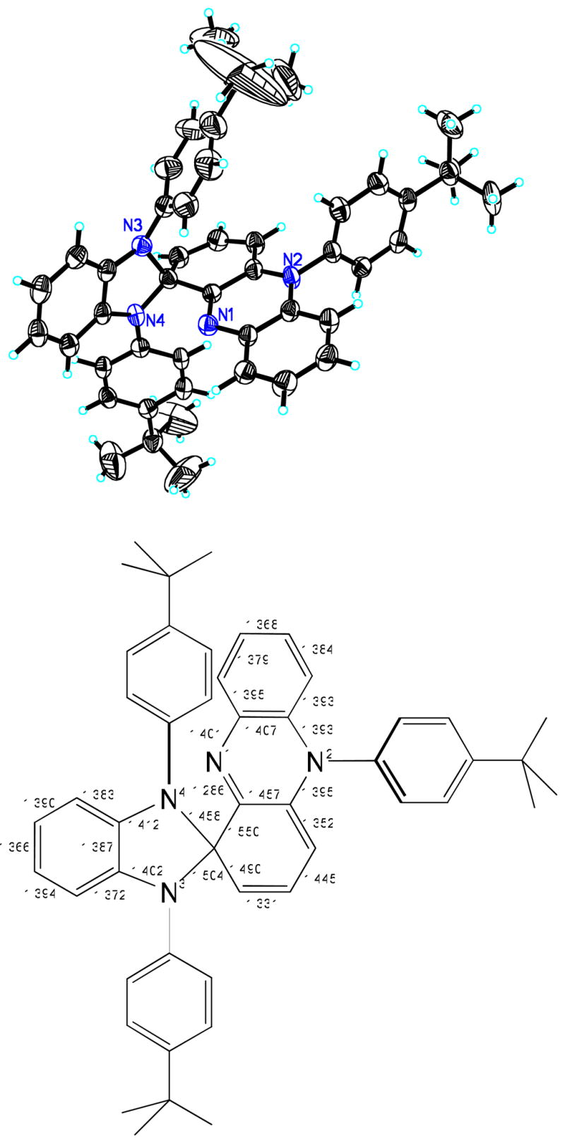
(Top) Solid-state structure of [L1re-4] (3) showing 50% probability ellipsoids and the atom labeling scheme. (Bottom) Selected interatomic distances (Å).
| (3) |
Electrochemistry
The cyclic voltammogram of 1a in THF (Figure 7) shows one wave at E1/2 value of −0.228 V (ΔE = 111 mV, ip,a/ip,c = 1.12), most likely due to the Mn(II)/Mn(III) couple, followed by two-electron anodic waves at 0.415 and 0.628 V and a cathodic wave at −0.294 V (vs. the Fc+/Fc couple). Similar behavior has been observed7 with the electrochemical oxidation of tetrahydrofuran solutions of [(L1)Fe(II) –THF] −, albeit at more accessible potentials, and assigned to independent one-electron Fe(II)/Fe(III) (quasi-reversible wave) and two-electron (L1) –Fe(II) → (L1re–1) –Fe(III) (first anodic wave) transformations. It is thus likely that the 0.415 V anodic wave is due to (L1) –Mn(II) → (L1re–1) –Mn(III) and that the S = 3/2 EPR signal which is consistent with a formal Mn(IV) mononuclear site observed by EPR in the early stages of the reaction of Mn(II) with dioxygen may be equivalent to the electrochemically accessible (L1re–1) –Mn(III) species. Furthermore, the presence of both Mn(III) and (L1re–1) –Mn(III) containing sites may be responsible for providing the initial Mn(III)Mn(III)(L•) compound as indicated by EPR spectroscopy.
Figure 7.

Cyclic voltammogram of [(L1)Mn(II)–THF][K(THF)x] (1a) in THF/[(n-Bu)4N]PF6 (0.5 M) with a Au disk electrode (1.6 mm in diameter); scan rate 0.1 V/s. Arrow indicates direction of scan.
The oxidation of 2 was examined by cyclic voltammetry in THF (Figure 8) and MeCN. In both cases the main feature of the voltammograms are two anodic/cathodic waves at E1/2 values of −0.402 (ΔE = 63 mV) and −0.191 (ΔE = 102 mV) V. It is more likely that those represent ligand- rather than metal-centered events, especially since the E1/2 values (vs. Ag/AgCl)30 are low with respect to values reported for Mn(III)Mn(III) → Mn(III)Mn(IV) and Mn(III)Mn(IV) → Mn(IV)Mn(IV) couples (Table 2). In addition, an irreversible wave at Ep,a = 0.079 V and two cathodic waves at −0.018 and −0.547 V are noted (Figure 8, marked with asterisks), which are all dominant features in the cyclic voltammogram of the metal-free species 3 (Figure S4 in the Supporting Information). The intensity of the features associated with 3 increases upon exposure of 2 to dioxygen at the expense of the aforementioned waves at −0.402 and −0.191 V.
Figure 8.

Cyclic voltammogram of [(L1re–1)Mn(III)–(O)2–Mn(III)(L1re–1)][K(OC2H5)]2 (2) in THF/[(n-Bu)4N]PF6 (0.5 M) with a Au disk electrode (1.6 mm in diameter); scan rate 0.1 V/s. Arrow indicates direction of scan.
Synthesis of Cr(III) Complexes
In order to establish whether the behavior of ligand L1H3 with respect to Cr(III) sites is similar to that encountered with Mn(III) complexes, the deprotonated ligand K3L1 was reacted with anhydrous CrCl3 in THF to afford dark brown-green solutions. Two air-sensitive products can be isolated from this reaction. Brown hexane extracts afford needle-like crystals of [(L1re–1)Cr(III)–(Cl)(THF)]·0.75C6H14 (4), whereas the residue can be crystallized from diethyl ether to provide dark green, diamond-shaped crystals of [(L1)Cr(III)–(THF)] (5). Hence, both the intact and the oxidatively rearranged ligand are featured in 5 and 4, respectively. The quantitative generation of 4 from 5 in THF according to Eq. 4 provides an explanation for the formation of both species in the reaction of L13K and CrCl3.
| (4) |
Thus CrCl3 acts both as a ligand metallation source and an oxidizing agent. The first oxidizing equivalent above the Cr(III) level is therefore directed toward the ligand, in sharp contrast to the well-established silyl-derivatized, TREN-containing compound [Cr(III)(N3N)] which is reportedly oxidized by CuCl2 to [Cr(IV)(N3N)Cl] (Scheme 4)31 as well as by other oxidants such as AgX and halogens.32 The intricacies of assigning electronic structures to chromium complexes featuring ligand-centered radicals are nicely demonstrated in a recent publication by Wieghardt and co-workers.33
Scheme 4.

The structure of 4 (Figure 9) displays a distorted octahedral geometry, in which the axis defined by O(1)–Cr(1)–N(1) (175.31°) makes the closest approach to linearity. The ligand is rearranged as in compound 2 and also retains the one-electron oxidized o-disq− moiety between nitrogen atoms N(1) and N(2), as indicated by the average C–N distance of 1.361(6) Å and the pattern of four long (C(33)–C(34) 1.435(6), C(34)–C(35) 1.409(7), C(36)–C(37) 1.401(7), C(33)–C(38) 1.409(6) Å) and two short (C(35)–C(36) 1.356(7), C(37)–C(38) 1.378(7) Å) C–C bonds. On the other hand, the Cr(1)–N(1) and Cr(1)–N(2) bond distances (1.932(4), 1.959(4) Å) associated with the semi-imino residues are shorter than that observed for the genuine amido moiety (Cr(1)–N(4) = 2.019(4) Å). The shorter bonds can be explained by taking into account the position of atoms N(1) and N(2) trans to the weakly coordinating THF and N(3)amine moieties, respectively, whereas the location of atom N(4) is influenced by the strong trans effect of the coordinated chloride.
Figure 9.

Solid-state structure of [(L1re–1)Cr(III)–(Cl)(THF)]·2C6H14 (4) showing 50% probability ellipsoids and the atom labeling scheme. Selected interatomic distances (Å) and angles (deg): Cr(1) –N(1) 1.932(4), Cr(1) –N(2) 1.959(4), Cr(1) –N(4) 2.019(4), Cr(1) –O(1) 2.102(3), Cr(1) –N(3) 2.216(3), Cr(1) –Cl(1) 2.3452(13), N(1) –Cr(1) –N(2) 81.19(16), N(1) –Cr(1) –N(4) 94.76(15), N(2) –Cr(1) –N(4) 94.14(15), N(1) –Cr(1) –N(3) 80.63(14), N(2) –Cr(1) –N(3) 160.57(15), N(3) –Cr(1) –N(4) 80.62(13), N(1) –Cr(1) –Cl(1) 88.70(11), N(2) –Cr(1) –Cl(1) 92.97(11), N(3) –Cr(1) –Cl(1) 93.41(9), N(4) –Cr(1) –Cl(1) 172.50(12), N(1) –Cr(1) –O(1) 175.31(14).
The structure of 5 (Figure 10) establishes that the ligand remains intact and that the compound possesses a distorted trigonal bipyramidal geometry with slight deviation from C3 symmetry. The chromium ion lies 0.27 Å above the plane defined by the three sp2 hybridized Namido atoms in the direction of the coordinated THF. The average Cr–Namido bond distance (1.957(3) Å) is similar to that encountered in 4, but significantly longer than the corresponding average value of 1.877(3) Å reported for [Cr(III)(N3N)] due to the reduced basicity of Ar2N– moiety. Conversely, the weakened axial coordination of [Cr(III)(N3N)] features a longer Cr–Namine bond distance (2.243(3) Å) than that observed in 5 (2.094(3) Å).
Figure 10.

Solid-state structure of [(L1)Cr(III) –THF] (5) showing 50% probability ellipsoids and the atom labeling scheme. Selected interatomic distances (Å) and angles (deg): Cr(1) –N(1) 2.094(3), Cr(1) –N(2) 1.969(3), Cr(1) –N(3) 1.943(3), Cr(1) –N(4) 1.965(3), N(1) –C(13) 1.474(5), N(1) –C(1) 1.479(4), N(1) –C(7) 1.486(4), N(2) –C(12) 1.373(5), N(2) –C(19) 1.427(5), N(3) –C(6) 1.398(4), N(3) –C(29) 1.439(5), N(4) –C(18) 1.397(4), N(4) –C(39) 1.423(5), N(3) –Cr(1) –N(4) 124.20(13), N(3) –Cr(1) –N(2) 125.96(14), N(4) –Cr(1) –N(2) 104.34(14), N(3) –Cr(1) –O(1) 94.95(12), N(4) –Cr(1) –O(1) 102.30(12), N(2) –Cr(1) –O(1) 96.58(12), N(3) –Cr(1) –N(1) 82.14(12), N(4) –Cr(1) –N(1) 82.78(13), N(2) –Cr(1) –N(1) 81.90(12).
Mechanistic Considerations
With reference to Scheme 5, the oxidative rearrangement of metallated ligand [L1]3− to [L1re-1]2− has been previously established to occur via an initial one-electron transfer to an Namido residue to generate an electrophilic aminyl radical. This N-centered radical then undergoes a 1,4-(N-to-N) phenyl migration, while the initial oxidation equivalent is retained in a newly formed disq− ring. Downstream oxidative events, leading to the metal-free [L1re-4], most likely follow a similar pattern, enabled by initial oxidation of the genuine N(4)amido residue of 2, which is electron-rich due to the weak coordination to Mn(III). The ensuing five-member imidazolato ring is trapped in [L1re-4], since radical coupling is apparently preferred over ring opening. This process generates the central imino nitrogen N(1) of [L1re-4], which then protects the adjacent carbon from repetition of the same process by the newly formed aminyl radical, generated by one-electron oxidation of the remaining amido residue. Instead, the aminyl radical adds to an ortho position to form the six-member ring. The removal of the bridgehead H atom is more contentious and is probably driven thermodynamicaaly by dioxygen addition to the allylic cyclohexenyl radical, followed by elimination of a hydroperoxyl radical. It is worthwhile noting that [L1re-4] possesses structural elements of the celebrated Perkin’s mauveine-type compounds.34
Scheme 5.

Conclusions
The following are the principal findings of the present study:
Solutions of [(L1)Mn(II)–THF] − (1a) in THF can be oxidized by dioxygen to afford the dioxo-bridged compound [(L1re–1)Mn(III)–(O)2–Mn(III)(L1re–1)][K(OEt2)]2 (2). This compound contains a ligand that has been oxidatively rearranged, while retaining the oxidation equivalent as a π radical in a newly formed o-disq− moiety. The reduced basicity of the ligand and the steric encumbrance imposed, contribute towards stabilizing the rare Mn(III)(O)2Mn(III) core.
Compound 2 exhibits antiferromagnetic coupling, which is analyzed as being composed of a strong coupling between the S = ½ ligand-centered radical and the S = 2 Mn(III) ion and a more modest coupling between the two Mn(III) ions via the two oxo bridges. Compound 2 also shows rich electrochemical behavior, indicating storage of additional oxidation equivalents whose location is deemed to be ligand centered.
CrCl3 can provide the necessary oxidizing equivalent to oxidize compound [(L1)Cr(III) –THF] (5), featuring the intact C3-symmetric ligand, to the corresponding six-coordinate species [(L1re–1)Cr(III)–(Cl)(THF)] (4). As with the case of manganese, one-electron oxidation above the Cr(III) level is ligand-centered, causing the same ligand rearrangement and retention of the oxidation equivalent as a π radical.
The oxidation of the ligand is perceived to occur via an incipient metal-bound aminyl radical that is generated upon a one-electron ligand oxidation. This electrophilic radical is then engaged in rearrangement reaction, which amounts to an internal 1,4(N-to-N) radical aryl migration. The rearrangement gives rise to an o-diiminobenzosemiquinonate type moiety, which stabilizes the oxidation equivalent as a π radical.
Future studies will be directed towards elucidating the redox events above the [[(L1re–1)–M(III)] oxidation level, as suggested by current electrochemical results.
Supplementary Material
X-band EPR spectra of 1a in THF (Figure S1), IR spectrum of 2 (Figure S2), X-band EPR spectra of compounds 1a and 2 after exposure to dioxygen (Figure S3), cyclic voltammogram of 3 (Figure S4), and X-ray crystallographic data for compounds 1–5 in CIF format. The material is available free of charge via the Internet at http://pubs.acs.org.
Figure 1.

Solid-state structure of [(L1)Mn(II) –THF](Ph4P)·3THF (1b) showing 50% probability ellipsoids and the atom labeling scheme (the countercation (Ph4P)+ and the solvated THF molecules have been omitted for clarity). Selected interatomic distances (Å) and angles (deg): Mn(1) –N(3) 2.084(3), Mn(1) –N(4) 2.088(3), Mn(1) –N(2) 2.113(3), Mn(1) –O(1) 2.228(3), Mn(1) –N(1) 2.316(3), N(3) –Mn(1) –N(4) 114.92(12), N(3) –Mn(1) –N(2) 115.19(11), N(4) –Mn(1) –N(2) 114.68(12), N(3) –Mn(1) –O(1) 109.57(11), N(4) –Mn(1) –O(1) 99.73(11), N(2) –Mn(1) –O(1) 100.23(11), N(3) –Mn(1) –N(1) 76.91(10), N(4) –Mn(1) –N(1) 77.03(11), N(2) –Mn(1) –N(1) 76.39(10).
Scheme 3.

Acknowledgments
We thank Drs. Vassilis Tangoulis, Charles Barnes, Jeff R. Long, Louise Berben, Nicholas Leventis, George D. Chryssikos, Spyros Koinis, and Thomas Mavromoustakos for experimental assistance and useful discussions. We gratefully acknowledge generous financial support (to P.S.) by the NSF (CHE-0412959) and in part by the NIH/NIEHS (5 P42 ES007381). We also acknowledge NSF funding (CHE-0420497) for the purchase of the diffractometer at the University of Missouri-St. Louis.
References
- 1.(a) Larrow JF, Jacobsen EN. Topics Organomet Chem. 2004;6:123–152. [Google Scholar]; (b) Lee TV. In: Comprehensive Organic Synthesis. Trost BM, Fleming I, editors. Vol. 7. Pergamon; Oxford: 1990. pp. 291–303. [Google Scholar]
- 2.(a) Luzzio FA. Org React. 1998;53:1–221. [Google Scholar]; (b) Ley SV, Maddin A. In: Comprehensive Organic Synthesis. Trost BM, Fleming I, editors. Vol. 7. Pergamon; Oxford: 1990. pp. 251–289. [Google Scholar]
- 3.(a) Dismukes GC. Chem Rev. 1996;96:2909–2926. doi: 10.1021/cr950053c. [DOI] [PubMed] [Google Scholar]; (b) Mukhopadhyay S, Mandal SK, Bhaduri S, Armstrong WH. Chem Rev. 2004;104:3981–4026. doi: 10.1021/cr0206014. [DOI] [PubMed] [Google Scholar]; (c) Wu AJ, Penner-Hahn JE, Pecoraro VL. Chem Rev. 2004;104:903–938. doi: 10.1021/cr020627v. [DOI] [PubMed] [Google Scholar]; (d) Jedrzejas MJ, Setlow P. Chem Rev. 2001;101:607–618. doi: 10.1021/cr000253a. [DOI] [PubMed] [Google Scholar]; (e) Gold MH, Youngs HL, Sollewijn G, Maarten D. In: Metal Ions in Biological Systems: Manganese and Its Role in Biological Processes. Sigel A, Sigel H, editors. Vol. 37. Marcel Dekker, Inc; New York, Basel: 2000. pp. 559–586. [PubMed] [Google Scholar]; (f) Ash DE, Cox JD, Christianson DW. In: Metal Ions in Biological Systems: Manganese and Its Role in Biological Processes. Sigel A, Sigel H, editors. Vol. 37. Marcel Dekker, Inc; New York, Basel: 2000. pp. 407–428. [PubMed] [Google Scholar]; (g) Bogumil R, Kappl R, Huttermann J. In: Metal Ions in Biological Systems: Manganese and Its Role in Biological Processes. Sigel A, Sigel H, editors. Vol. 37. Marcel Dekker, Inc; New York, Basel: 2000. pp. 365–405. [PubMed] [Google Scholar]; (h) Rusnak F. In: Metal Ions in Biological Systems: Manganese and Its Role in Biological Processes. Sigel A, Sigel H, editors. Vol. 37. Marcel Dekker, Inc; New York, Basel: 2000. pp. 305–343. [PubMed] [Google Scholar]; (i) Crowley JD, Traynor DA, Weatherburn DC. In: Metal Ions in Biological Systems: Manganese and Its Role in Biological Processes. Sigel A, Sigel H, editors. Vol. 37. Marcel Dekker, Inc; New York, Basel: 2000. pp. 209–278. [PubMed] [Google Scholar]; (j) Christianson DW, Cox JD. Annu Rev Biochem. 1999;68:33–57. doi: 10.1146/annurev.biochem.68.1.33. [DOI] [PubMed] [Google Scholar]; (k) Weatherburn DC. Perspectives on Bioinorganic Chemistry. 1996;3:1–113. [Google Scholar]
- 4.(a) Brautigan DL, Kruszewski A, Wang H. Biochem Biophys Res Commun. 2006;347:769–773. doi: 10.1016/j.bbrc.2006.06.154. [DOI] [PubMed] [Google Scholar]; (b) Wang H, Kruszewski A, Brautigan DL. Biochemistry. 2005;44:8167–8175. doi: 10.1021/bi0473152. [DOI] [PubMed] [Google Scholar]; (c) Kawanishi S, Inoue S, Sano S. J Biol Chem. 1986;261:5952–5958. [PubMed] [Google Scholar]; (d) Shi X, Dalal NS. Biochem Biophys Res Commun. 1988;156:137–142. doi: 10.1016/s0006-291x(88)80815-5. [DOI] [PubMed] [Google Scholar]
- 5.Jiang W, Yun D, Saleh L, Barr EW, Xing G, Hoffart LM, Maslak MA, Krebs C, Bollinger JM., Jr Science. 2007;316:1188–11-91. doi: 10.1126/science.1141179. [DOI] [PubMed] [Google Scholar]
- 6.(a) Goodson PA, Glerup J, Hodgson DJ, Michelsen K, Pedersen E. Inorg Chem. 1990;29:503–508. [Google Scholar]; (b) Goodson PA, Glerup J, Hodgson DJ, Michelsen K, Weihe H. Inorg Chem. 1991;30:4909–4914. [Google Scholar]; (c) Manchanda R, Brudvig GW, de Gala S, Crabtree RH. Inorg Chem. 1994;33:5157–5160. [Google Scholar]; (d) Jensen AF, Su Z, Hansen NK, Larsen FK. Inorg Chem. 1995;34:4244–4252. [Google Scholar]; (e) Horner O, Charlot M-F, Boussac A, Anxolabéhére-Mallart E, Tchertanov L, Guilhem J, Girerd J-J. Eur J Inorg Chem. 1998:721–727. doi: 10.1021/ic980832m. [DOI] [PubMed] [Google Scholar]; (f) Hureau C, Blondin G, Cesario M, Un S. J Am Chem Soc. 2003;125:11637–11645. doi: 10.1021/ja035153b. [DOI] [PubMed] [Google Scholar]; (g) Chen H, Tagore R, Das S, Incarvito C, Faller JW, Crabtree RH, Brudvig GW. Inorg Chem. 2005;44:7661–7670. doi: 10.1021/ic0509940. [DOI] [PubMed] [Google Scholar]
- 7.(a) Hoganson CW, Babcock GT. Science. 1992;277:1953–1956. doi: 10.1126/science.277.5334.1953. [DOI] [PubMed] [Google Scholar]; (b) Petrouleas V, Koulougliotis D, Ioannidis N. Biochemistry. 2005;44:6723–6728. doi: 10.1021/bi0503201. [DOI] [PubMed] [Google Scholar]
- 8.Çelenligil-Çetin R, Paraskevopoulou P, Dinda R, Lalioti N, Sanakis Y, Rawashdeh AM, Staples RJ, Sinn E, Stavropoulos P. Eur J Inorg Chem. 2008:673–677. doi: 10.1021/ic801219u. [DOI] [PMC free article] [PubMed] [Google Scholar]
- 9.(a) Çelenligil-Çetin R, Paraskevopoulou P, Dinda R, Staples RJ, Sinn E, Rath NP, Stavropoulos P. Inorg Chem. 2008;47:1165–1172. doi: 10.1021/ic702154z. [DOI] [PubMed] [Google Scholar]; (b) Jones MB, MacBeth CE. Inorg Chem. 2007;46:8117–8119. doi: 10.1021/ic701289y. [DOI] [PubMed] [Google Scholar]
- 10.Pinnapareddy D, Paraskevopoulou P, Stavropoulos P. manuscript in preparation. [Google Scholar]
- 11.Pierce BS, Elgren TE, Hendrich MP. J Am Chem Soc. 2003;125:8748–8759. doi: 10.1021/ja021290h. [DOI] [PubMed] [Google Scholar]
- 12.Studer A, Bossart M. Tetrahedron. 2001;57:9649–9667. [Google Scholar]
- 13.(a) Herebian D, Wieghardt KE, Neese F. J Am Chem Soc. 2003;125:10997–11005. doi: 10.1021/ja030124m. [DOI] [PubMed] [Google Scholar]; (b) Chaudhuri P, Verani CN, Bill E, Bothe E, Weyhermüller T, Wieghardt K. J Am Chem Soc. 2001;123:2213–2223. doi: 10.1021/ja003831d. [DOI] [PubMed] [Google Scholar]
- 14.Gultneh Y, Yisgedu TB, Tesema YT, Butcher RJ. Inorg Chem. 2003;42:1857–1867. doi: 10.1021/ic020131w. [DOI] [PubMed] [Google Scholar]
- 15.Mikata Y, So H, Yamashita A, Kawamura A, Mikuriya M, Fukui K, Ichimura A, Yano S. Dalton Trans. 2007:3330–3334. doi: 10.1039/b705080a. [DOI] [PubMed] [Google Scholar]
- 16.Goodson PA, Oki AR, Glerup J, Hodgson DJ. J Am Chem Soc. 1990;112:6248–6254. [Google Scholar]
- 17.Goodson PA, Hodgson DJ. Inorg Chem. 1989;28:3606–3608. [Google Scholar]
- 18.Kitajima N, Singh UP, Amagai H, Osawa M, Moro-oka Y. J Am Chem Soc. 1991;113:7757–7758. [Google Scholar]
- 19.Glerup J, Goodson PA, Hazell A, Hazell R, Hodgson DJ, McKenzie CJ, Michelsen K, Rychlewska U, Toftlund H. Inorg Chem. 1994;33:4105–4111. [Google Scholar]
- 20.Hitomi Y, Ando A, Matsui H, Ito T, Tanaka T, Ogo S, Funabiki T. Inorg Chem. 2005;44:3473–3478. doi: 10.1021/ic050109d. [DOI] [PubMed] [Google Scholar]
- 21.(a) Huffman JC, Green MA, Kaiser SL, Caulton KG. J Am Chem Soc. 1985;107:5111–5115. [Google Scholar]; (b) Bouwkamp MW, Lobkovsky E, Chirik PJ. Inorg Chem. 2006;45:2–4. doi: 10.1021/ic051839o. [DOI] [PubMed] [Google Scholar]
- 22.(a) Kahn O. Molecular Magnetism. VCH Publihers; N. York: 1993. [Google Scholar]; (b) Andersen NH, Døssing A, Mølgaard A. Inorg Chem. 2003;42:6050–6055. doi: 10.1021/ic034428l. [DOI] [PubMed] [Google Scholar]
- 23.Law NA, Kampf JW, Pecoraro VL. Inorg Chim Acta. 2000;297:252–264. [Google Scholar]
- 24.Kachi-Terajima C, Miyasaka H, Sugiura KI, Clérac R, Nojiri H. Inorg Chem. 2006;45:4381–4390. doi: 10.1021/ic0519842. [DOI] [PubMed] [Google Scholar]
- 25.(a) Kessissoglou DP, Li X, Butler WM, Pecoraro V. Inorg Chem. 1987;26:2487–2492. [Google Scholar]; (b) Campbell KH, Lashley MR, Wyatt JK, Nantz MH, Britt RD. J Am Chem Soc. 2001;123:5710–5719. doi: 10.1021/ja0027463. [DOI] [PubMed] [Google Scholar]; (c) Hureau C, Anxolabéhére-Mallart E, Blondin G, Riviere E, Nierlich M. Eur J Inorg Chem. 2005:4808–4817. doi: 10.1021/ic050243y. [DOI] [PubMed] [Google Scholar]; (d) Parsell TH, Behan RK, Green MT, Hendrich MP, Borovik AS. J Am Chem Soc. 2006;128:8728–8729. doi: 10.1021/ja062332v. [DOI] [PubMed] [Google Scholar]
- 26.Lu CC, Bill E, Weyhermüller T, Bothe E, Wieghardt K. J Am Chem Soc. 2008;130:3181–3197. doi: 10.1021/ja710663n. [DOI] [PubMed] [Google Scholar]
- 27.(a) Dismukes GC, Siderer Y. Proc Natl Acad Sci USA. 1981;78:274–278. doi: 10.1073/pnas.78.1.274. [DOI] [PMC free article] [PubMed] [Google Scholar]; (b) Pessiki PJ, Khangulov SV, Ho DM, Dismukes GC. J Am Chem Soc. 1994;116:891–897. [Google Scholar]
- 28.Kulik LV, Lubitz W, Messinger J. Biochemistry. 2005;44:9368–9374. doi: 10.1021/bi050411y. [DOI] [PubMed] [Google Scholar]
- 29.(a) Schäfer KO, Bittl R, Lendzian F, Barynin V, Weyhermüller T, Wieghardt K, Lubitz J. Phys Chem B. 2003;107:1242–1250. [Google Scholar]; (b) Horner O, Anxolabéhére-Mallart E, Charlot M-F, Tchertanov L, Guilhem J, Mattioli TA, Boussac A, Girerd J-J. Inorg Chem. 1999;38:1222–1232. doi: 10.1021/ic980832m. [DOI] [PubMed] [Google Scholar]
- 30.Tsierkezos NG. J Solution Chem. 2007;36:289–302. [Google Scholar]
- 31.Schneider S, Filippou AC. Inorg Chem. 2001;40:4674–4677. doi: 10.1021/ic010361v. [DOI] [PubMed] [Google Scholar]
- 32.Filippou AC, Schneider S, Ziemer B. Eur J Inorg Chem. 2002:2928–2935. [Google Scholar]
- 33.Lu CC, DeBeer George S, Weyhermüller T, Bill E, Bothe E, Wieghardt K. Angew Chem Int Ed. 2008;47:6384–6387. doi: 10.1002/anie.200800669. [DOI] [PubMed] [Google Scholar]
- 34.(a) Seixas de Melo J, Takato S, Sousa M, Melo MJ, Parola AJ. Chem Commun. 2007:2624–2626. doi: 10.1039/b618926a. [DOI] [PubMed] [Google Scholar]; (b) Sousa MM, Melo MJ, Jorge Parola A, Morris PJT, Rzepa HS, Sérgio Seixas de Melo J. Chem Eur J. 2008 early view. [Google Scholar]
Associated Data
This section collects any data citations, data availability statements, or supplementary materials included in this article.
Supplementary Materials
X-band EPR spectra of 1a in THF (Figure S1), IR spectrum of 2 (Figure S2), X-band EPR spectra of compounds 1a and 2 after exposure to dioxygen (Figure S3), cyclic voltammogram of 3 (Figure S4), and X-ray crystallographic data for compounds 1–5 in CIF format. The material is available free of charge via the Internet at http://pubs.acs.org.