Abstract
The risk of dislocation after THA reportedly is minimized if the acetabular implant is oriented at 45° inclination and 15° anteversion with respect to the anterior pelvic plane. This reference plane now is used in computer-assisted protocols. However, this static approach may lead to postoperative instability because the dynamic variations of the pelvis influence effective cup orientation and are not taken into account in this approach. We propose an ultrasound tool to register the preoperative dynamics of the pelvis for THA planning during computer-assisted surgery. To assess this pelvic behavior and its consequences on implant orientation, we tested a new 2.5-dimensional ultrasound-based approach. The pelvic flexion was registered in sitting, standing, and supine positions in 20 subjects. The mean values were −25.2° ± 5.8° (standard deviation), 2.4° ± 5.1°, and 6.8° ± 3.5°, respectively. The mean functional anteversion varied by 26° and the mean functional inclination by 12° depending on the pelvic flexion. We therefore recommend including dynamic pelvic behavior to minimize dislocation risk. The notion of a safe zone should be revisited and extended to include changes with activity.
Introduction
Postoperative stability of THA is the consequence of acetabular and femoral implant orientations, balance of soft tissues, and restored leg length and offset [1, 6, 13]. Despite much work to enhance implant orientation, some studies report a residual rate of dislocation from 1% to as much as 6% [6, 18]. Lewinnek et al. [11] reported this risk could be minimized if the acetabular implant is oriented at 45° inclination and 15° anteversion with respect to the anterior pelvic plane. Although the safe zone as defined by Lewinnek et al. [11] generally is accepted by the orthopaedic community, some authors emphasize dislocations may occur even with well-oriented implants [7, 16]. Therefore, one may argue static recommendations may not be sufficient in addressing the dynamic issue of implant stability.
The dynamic behavior of the pelvis influences orientation of the acetabulum during daily activities like sitting, standing, or lying supine [3, 8, 16]. These variations maximize the natural range of motion of the hip (eg, maximize flexion in sitting or extension in supine positions) and should be taken into consideration after THA because they may interfere with postoperative stability in routine daily activities.
Numerous attempts to assess dynamic pelvic behavior are based on radiographic approaches (plain radiographs or computed tomography) or on inclinometers [3, 4, 8–10, 16]. However, using these approaches in sitting, standing, and lying positions take time, may be expensive, and most expose the patient to radiation. One study reported a three-dimensional articulated arm to digitize superficial anatomic landmarks to establish the frontal pelvic plane and assess pelvic behavior [12]. However, this procedure does not take into account the depth of the intervening tissue, ie, the skin and subcutaneous tissue. These procedures cannot be used routinely because they lack of accuracy and are very complex. We therefore considered an ultrasound-based method to assess the dynamic behavior of the pelvis which potentially could be accurate, quick, reproducible, and avoid radiation.
Our purposes in this study were (1) to assess the accuracy and intraobserver and interobserver reproducibilities of this method; (2) to study the dynamic behavior of the pelvis in 20 subjects with this procedure; and (3) to evaluate the consequences of this dynamic on the functional orientation of a cup.
Materials and Methods
We developed an acquisition protocol suitable for the daily practice of orthopaedic surgeons, which could register the preoperative dynamics of the pelvis. The protocol required three positions: standing, sitting, and supine. We then computed the functional orientation of the acetabulum as defined by Lazennec [7]. We made these measurements on 20 healthy male volunteers who were members of the laboratory. Age, height, and weight were recorded for each. Their mean age was 30 years (standard deviation, 7 years; range, 16–41 years), mean height was 1.79 ± 0.04 m (range, 1.72–1.88 m), and mean weight was 75 ± 9 kg (range, 62–90 kg). None had specific problems.
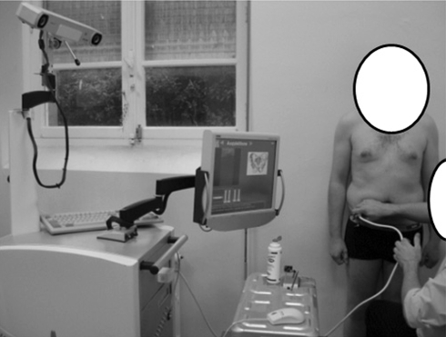
The device was composed of a three-dimensional (3-D) stereoscopic infrared localizer and a two-dimensional (2-D) ultrasound probe. Both technologies were integrated in a navigation workstation (Surgetics®) developed by PRAXIM-Medivision (La Tronche-Grenoble, France) for computer-assisted orthopaedic surgery (Fig. 1). The infrared localizer (Polaris from NDI, Ontario, Canada) was able to localize in a 3-D volume any object equipped with a retroreflective tracker. The root mean square error of this optical system is as low as 0.35 mm according to the manufacturer. These trackers, called rigid bodies, can be installed on bones or on surgical instruments. In our experiment, a tracker was installed on a linear ultrasound probe HL7.5/40/128D from Telemed® (Vilnius, Lithuania).
Fig. 1.
The navigation workstation with the ultrasound probe is shown.
We developed a specific method to perform the calibration of the ultrasound probe based on a special phantom, which could simulate data, and which allowed us to obtain an accurate procedure without human resources. The calibration method can be performed automatically without any technical or clinical skills (Appendix 1). The calibration allowed the computation of the transformation matrix required to obtain the 3-D positions of any points of the 2-D ultrasound image. The accuracy was less than 1 mm, which is similar to published results using nonautomatic and slower approaches [2, 14, 17].
To assess the dynamic behavior of the pelvis and orientation of the cup, we first needed to define a specific reference system based on the pelvis. We used the anterior pelvic plane as a static reference system, as suggested by Lewinnek et al. [11]. This plane is defined by the two anterior-superior iliac spines and the pubic symphysis [5, 11]. This choice was made because of the major role given to this plane in currently used computer-assisted surgical protocols.
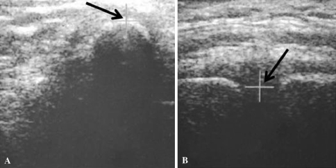
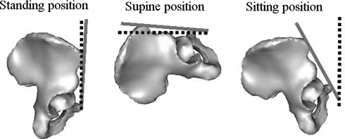
To compute the anterior pelvic plane, these three specific points were digitized on subjects using the 2.5D ultrasound probe. Therefore, the three regions of interest were scanned, providing three different ultrasound images. With a specific interface, the user localized the anatomic landmarks interactively in the ultrasound images. The iliac spine is the top of the bone interface (Fig. 2A) and the pubic symphysis is the middle of the two bone interfaces (Fig. 2B). The pelvic plane then was defined in 3-D by these three 3-D points. The pelvic flexion was computed as the difference between orientation of the anterior pelvic plane and a reference vertical plane known thanks to the localizer in the sagittal plane (Fig. 3).
Fig. 2A–B.
Ultrasound images show (A) an iliac spine and (B) the symphysis with interactive detection with a cursor.
Fig. 3.
The diagrams illustrate the definition of pelvic flexion in standing, supine, and sitting positions. Pelvic flexion was computed as the difference between the orientation of the anterior pelvic plane (solid line) and a reference plane (dotted line) known thanks to the localizer in the sagittal plane.
This procedure was performed with the subject standing, sitting on a chair, and lying supine. We established specific requirements to ensure reproducibility of the sitting position from one subject to the other and for each subject from one experiment to the other. In the supine position, we used a horizontal reference plane instead of the vertical plane.
Accuracy of the detection was assessed by using a plane phantom. For each position of the plane, we compared the value given by the ultrasound approach with respect to the one given by the mechanical goniometer. We put the plane in eight successive inclinations from 10° to 80° (10°, 20°, 30°, 40°, 50°, 60°, 70°, 80°) according to the mechanical goniometer. These true values then were compared with the measurements obtained with the ultrasound approach. After this accuracy study, we performed reproducibility tests to assess intraobserver and interobserver variabilities of the measurements. One healthy volunteer was selected randomly from the 20 patients. The pelvic flexion was measured eight times in the three positions and with two different observers (GD and SD).
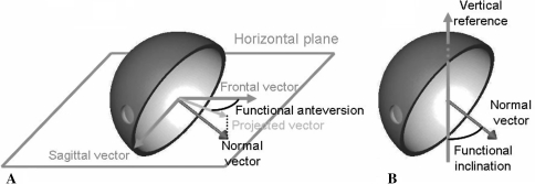
We then computed the functional orientation of the acetabulum. The orientation of the acetabulum with respect to the femoral component is the result of two parameters: (1) orientation of the cup with respect to the bone, which is a consequence of the surgical procedure (Parameter 1); and (2) orientation of the pelvic bone in 3-D space (Parameter 2). To assess this orientation, we found the mathematical equations that gave the values of the functional anteversion and inclination of the cup as a function of Parameters 1 and 2. Functional anteversion is computed in the transverse plane, parallel to the horizontal reference, between the projected vector and the frontal vector. Functional inclination is computed between the vertical reference and the normal vector of the acetabular implant (Fig. 4).
Fig. 4A–B.
The diagrams illustrate the definition of (A) functional anteversion and (B) inclination. Functional anteversion is computed in the transverse plane, parallel to the horizontal reference, between the projected vector and the frontal vector. Functional inclination is computed between the vertical reference and the normal vector of the acetabular implant.
These measurements were obtained for the 20 volunteers and the values of functional anteversion and inclination as a function of Parameters 1 (morphologic anteversion and inclination) and 2 (pelvic flexion at time [t]) were computed. Their absolute values can be obtained using the following equations:
 |
1 |
 |
2 |
where incl. = acetabular inclination, ante. = acetabular anteversion, flex. = pelvic flexion.
Results
The maximum difference between the goniometer and the values obtained with the ultrasound approach was less than 1° (accuracy, 0.7° ± 0.2°; range, 0.4°–0.9°). Reproducibility was assessed by measuring the standard deviation of eight measurements performed on one patient. The standard deviation varied from 0.6° (pelvic flexion, 4.9° ± 0.6°; range, 3.9°–5.7°) in the supine position to 1.2° (pelvic flexion, −29.4° ± 1.2°; range, −30.9° to −27.5°) in the sitting position. In the standing position, it was 1.1° (pelvic flexion, −4.8° ± 1.1°; range, −6.2° to −3.4°). The interobserver variability on this same patient was less than 1° for each position (range, 0.4°–0.9°).
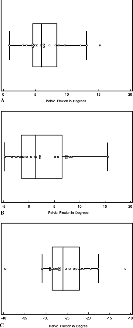
We observed a large range of pelvic flexion in the three positions and between subjects. The mean pelvic flexion values for the 20 subjects were 6.8° ± 3.5° (range, 0.9°–15.2°), 2.4° ± 5.1° (range, −4.8°–15.5°), and −25.2° ± 5.8° (range, −39.6° to −11.2°) in supine, standing, and sitting positions, respectively (Fig. 5).
Fig. 5A–C.
The graphs show pelvic flexion values for 20 subjects in the (A) supine, (B) standing, and (C) sitting positions. The central box represents the lower to upper quartiles (25th and 75th percentiles). The middle line represents the median. The horizontal line extends from the minimum to the maximum values, excluding the outliers, which are displayed as separated points.
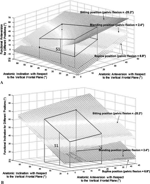
Effective anteversion and inclination varied widely depending on the position. The morphologic anteversion varied from 0° to 30° and inclination varied from 30° to 60° (Fig. 6).
Fig. 6A–B.
(A) Functional anteversion and (B) functional inclination are shown as functions of anatomic inclination and anteversion for the three measured positions. The dynamic volume is represented by the solid lines. S1 represents variation of the values for one patient with a specific anatomic orientation of the cup. Each surface describes the variation of its values for one specific position, respectively, from bottom to top, supine (mean flexion, 6.9°), standing (mean flexion, 2.4°), and sitting (mean flexion, −25.2°).
Discussion
As seen in previous studies [6, 13], postoperative stability of THA relies on the relative orientation of the cup with respect to the stem. Guidelines have been published, but most are static recommendations in local reference systems. Lazennec et al. [7, 8] and Nishihara et al. [16] described the major role played by the dynamic of the pelvis on stability of the hip. These studies, however, were based on radiographs or computed tomography, which makes them difficult to use in daily clinical practice because of radiation issues. An ultrasound-based method was developed. The purposes of our study were to assess the accuracy and intraobserver and interobserver reproducibility of this method, to study the dynamic behavior of the pelvis for 20 subjects with this procedure, and to evaluate the consequences of this dynamic on the functional orientation of a cup.
Our approach relies on the assumption that the dynamic behavior of the pelvis is similar before and after surgery. Nishihara et al. [16] and DiGioia et al. [3] concluded the changes in postoperative flexion were negligible. However, to further confirm this assumption, we need to perform a preoperative and postoperative ultrasound-based study. If the previous assumption was verified, then we would be able to perform dynamic specific patient-oriented procedures instead of applying generic morphologic rules to everyone. These procedures can be obtained easily with 2.5D ultrasound, but dissemination of such an approach will be possible only when portable navigation systems integrate ultrasound cards.
We first assessed the accuracy and reproducibility of the 2.5D ultrasound measurement tool. The global accuracy of the ultrasound approach meets our clinical needs with accuracy inferior to 1°. Measurement reproducibility was done and was lower in the sitting and standing positions than in the supine position, in which the standard deviation decreased to as low as 0.6°. This may reflect some line-of-sight issues observed in the 3-D optical localization of the probe and the fact that detection of the landmarks by the surgeons is easier in the supine position. However, regardless of the position, the reproducibility was still in an acceptable range with respect to the clinical objectives.
Pelvic flexion was assessed on 20 patients and, as in previous studies [3, 16], we observed important changes depending on the position of the subject. However, for a given individual in a given position, pelvic flexion is constant and reproducible. Our data were obtained, without any radiation, in less than 15 minutes per subject with an accuracy of 1°. This makes this approach usable in daily clinical use, unlike other reported methods [3, 4, 9, 12, 16]. The absolute values measured in this study, however, were similar (Table 1).
Table 1.
Pelvic flexion measurements
| Study | Supine (°) | Standing (°) | Sitting (°) |
|---|---|---|---|
| DiGioia et al. [3] | 1.2 ± 8.2 | −35.9 ± 12.6 | |
| Mayr et al. [12] | 5.6 ± 3.3 | 6.7 ± 3.6 | |
| Nishihara et al. [16] | 5 ± 9 | 3 ± 12 | −29 ± 12 |
| Current study | 6.8 ± 3.5 | 2.4 ± 5.1 | −25.2 ± 5.8 |
Values are mean ± standard deviation.
Finally, the functional orientation that defines the 3-D relationship between the cup and the stem is the result of three parameters: (1) the morphologic inclination; (2) the morphologic anteversion; and (3) the pelvic flexion (Fig. 4). To express our results in one common reference system, we assumed (as did Lewinnek et al. [11]) the anterior pelvic plane was vertical and we expressed all the values in the anatomic reference system as defined by Murray [15]. Lewinnek et al. [11] stated a safe zone could be defined based on the values of inclination and anteversion only. However, according to the definition of the functional anteversion and inclination of Lazennec et al. [7, 8], one can observe, for a given patient (with a specific anteversion and inclination), the functional values vary continuously between a maximum and a minimum depending on the function of the hip. For one specific patient, these variations can be represented on a graph by a vertical segment (S1). If we extend this approach to the whole population included inside the safe zone, as defined by Lewinnek et al., we obtain a functional volume (Vi) that represents all the possible functional values as a function of patient motion. The boundaries of this volume represent the minimum and maximum functional values that any patient inside the safe zone might achieve during functional activities. This volume is a good representation of the continuous dynamic behavior of the hip and could explain why some patients experience dislocation. Maximum functional values are sometimes far from anatomic values when the patient goes from standing to sitting.
Therefore, our data confirm that of another study [8]; the dynamic behavior may influence implant alignment and stability after THA, and we recommend integrating this notion in the planning. Because current planning of an implant is performed based on static morphologic data, the joint may impinge or become unstable. As dynamic behavior of the pelvis cannot be modified by the surgeon, we suggest the preoperative dynamics of pelvic flexion for each patient be measured and cup positioning made based on this dynamic information. Instead of choosing anatomic anteversion and inclination, one may choose the functional positioning in such a way that functional anteversion and inclination never reach the instability threshold.
Acknowledgment
We thank the members of the laboratory for their contributions in this study.
Appendix 1: Fully Automatic Calibration of an Ultrasound Probe
The calibration step of an US probe allows us to obtain the 3-D position of any point located on the 2-D ultrasonic (US) image using a 3-D localizer. This is therefore a crucial step for our application. Several methods can be found in the literature [14], however, some criteria are very important for clinical uses: accuracy, simplicity, robustness and rapidity. This appendix presents a fully automatic method based on a special phantom and on simulated data which can satisfy these constraints.
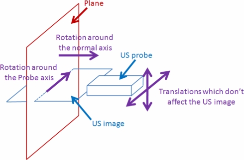
We observed that for the calibration method based on a plane [17], the US image didn’t change for some motions which are needed for a correct calibration. This is the case for the translations of the probe along the plane, the rotation about the normal axis of the plane and the rotation about an axis contained in the plane and in the US image (Probe axis) (Fig. 7).
Fig. 7.
Movements which do not affect the US image.
The simulation can therefore be used instead of carrying out manually those motions. To do that, we suppose that the US probe and the plane are fixed. The position and orientation of the US probe is recorded thanks to 3D localizer: this is our 3D initial virtual reference. In order to simulate the previous described motions, the transformations representing these motions are applied mathematically to this initial virtual reference. These four motions are therefore taken into account for the estimation of the calibration without any human interventions.
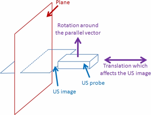
However, two remaining motions are needed to estimate correctly the calibration parameters: the translations of the probe on the normal axis of the plane and the rotation around the parallel vector (Fig. 8).
Fig. 8.
Movements which affect the US image.
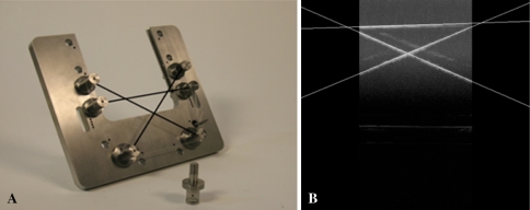
These motions introduce modifications on the US image and these modifications must therefore be estimated and applied to the initial image in order to simulate these two remaining movements. To do that, the scale factor must be first calculated and the rotation centre around the parallel vector must be visible on the US image. A phantom allowing us to realize it and to simulate all motions has been therefore developed (Fig. 9).
Fig. 9A–B.
The (A) calibration phantom and the (B) US image.
It consists of three nylon wires which form a simple triangle, where the base wire represents the surface of a virtual plane and the two others wires allow us to determine the scale factors and the rotation centre. The probe is fixed and aligned on this triangle during the procedure. Each wire has a known position in the space according to the rigid body attached on the phantom.
To evaluate the accuracy, 20 results were obtained by repeating the calibration procedure 20 times. A single point phantom was used to perform this evaluation. The accuracy was assessed by measuring the distance between this point and the positions of the 3D points obtained with the calibration results (Table 2).
Table 2.
| Mean accuracy (mm) | 0.91 |
| Standard deviation (mm) | 0.25 |
| Min. value (mm) | 0.48 |
| Max. value (mm) | 1.37 |
Our novel approach of US calibration is therefore based on mathematical simulation instead of manual positioning of the probe avoiding thus user intervention. In addition to potentially reducing the calibration time, the simulation provides accurate datasets using only one US image. The results of this fully automatic method show that it is not only easy and fast to perform but also accurate.
Footnotes
One or more of the authors (GD) have received funding from the French National Agency of Research, Réseau National des Technologies pour la Santé.
Each author certifies that his or her institution has approved the human protocol for this investigation and that all investigations were conducted in conformity with ethical principles of research, and that informed consent for participation in the study was obtained.
References
- 1.Chen E, Goertz W, Lill CA. Implant position calculation for acetabular cup placement considering pelvic lateral tilt and inclination. Comput Aided Surg. 2006;11:309–316. [DOI] [PubMed]
- 2.Dardenne G, Cano JD, Hamitouche C, Stindel E, Roux C. A new optimization approach for the calibration of an ultrasound probe using a 3D optical localizer. Conf Proc IEEE Eng Med Biol Soc. 2007;2007:3048–3051. [DOI] [PubMed]
- 3.DiGioia AM, Hafez MA, Jaramaz B, Levison TJ, Moody JE. Functional pelvic orientation measured from lateral standing and sitting radiographs. Clin Orthop Relat Res. 2006;453:272–276. [DOI] [PubMed]
- 4.Eddine TA, Migaud H, Chantelot C, Cotten A, Fontaine C, Duquennoy A. Variations of pelvic anteversion in the lying and standing positions: analysis of 24 control subjects and implications for CT measurement of position of a prosthetic cup. Surg Radiol Anat. 2001;23:105–110. [DOI] [PubMed]
- 5.Jaramaz B, DiGioia AM 3rd, Blackwell M, Nikou C. Computer assisted measurement of cup placement in total hip replacement. Clin Orthop Relat Res. 1998;354:70–81. [DOI] [PubMed]
- 6.Kluess D, Martin H, Mittelmeier W, Schmitz KP, Bader R. Influence of femoral head size on impingement, dislocation and stress distribution in total hip replacement. Med Eng Phys. 2007;29:465–471. [DOI] [PubMed]
- 7.Lazennec JY. Relations hanche rachis: conséquences fonctionnelles applications aux arthroplasties totales de hanche. Le Complexe Lombo-Pelvien: De L’anatomie à la Pathologie. Montpellier, France: Sauramps Medical; 2005.
- 8.Lazennec JY, Charlot N, Gorin M, Roger B, Arafati N, Bissery A, Saillant G. Hip-spine relationship: a radio-anatomical study for optimization in acetabular implant cup positioning. Surg Radiol Anat. 2004;26:136–144. [DOI] [PubMed]
- 9.Legaye J, Duval-Beaupère G, Hecquet J, Marty C. Pelvic incidence: a fundamental pelvic parameter for three-dimensional regulation of spinal sagittal curves. Eur Spine J. 1998;7:99–103. [DOI] [PMC free article] [PubMed]
- 10.Lembeck B, Mueller O, Reize P, Wuelker N. Pelvic tilt makes acetabular cup navigation inaccurate. Acta Orthop. 2005;76:517–523. [DOI] [PubMed]
- 11.Lewinnek GE, Lewis JL, Tarr R, Compere CL, Zimmerman JR. Dislocations after total hip replacement arthroplasties. J Bone Joint Surg Am. 1978;60:217–220. [PubMed]
- 12.Mayr E, Kessler O, Prassl A, Rachbauer F, Krismer M, Nogler M. The frontal pelvic plane provides a valid reference system for implantation of the acetabular cup: spatial orientation of the pelvis in different positions. Acta Orthop. 2005;76:848–853. [DOI] [PubMed]
- 13.McCollum DE, Gray WJ. Dislocation after total hip arthroplasty: causes and prevention. Clin Orthop Relat Res. 1990;261:159–170. [PubMed]
- 14.Mercier L, Langø T, Lindseth F, Collins DL. A review of calibration techniques for freehand 3-D ultrasound systems. Ultrasound Med Biol. 2005;31:143–165. [DOI] [PubMed]
- 15.Murray DW. The definition and measurement of acetabular orientation. J Bone Joint Surg Br. 1993;75:228–232. [DOI] [PubMed]
- 16.Nishihara S, Sugano N, Nishii T, Ohzono K, Yoshikawa H. Measurements of pelvic flexion angle using three-dimensional computed tomography. Clin Orthop Relat Res. 2003;411:140–151. [DOI] [PubMed]
- 17.Prager RW, Rohling RN, Gee AH, Berman L. Rapid calibration for 3-D freehand ultrasound. Ultrasound Med Biol. 1998;24:855–869. [DOI] [PubMed]
- 18.Sanchez-Sotelo J, Berry DJ. Epidemiology of instability after total hip replacement. Orthop Clin North Am. 2001;32:543–552, vii. [DOI] [PubMed]


