The crystal structure of C2b has been determined at 1.8 Å resolution, which reveals the arrangement of its three complement control protein (CCP) modules. A model for complement component C2 is presented and its conformational changes during the C3-convertase formation are also discussed.
Keywords: human complement system, complement control proteins, C2b, complement components, C3 convertase
Abstract
The second component of complement (C2) is a multi-domain serine protease that provides catalytic activity for the C3 and C5 convertases of the classical and lectin pathways of human complement. The formation of these convertases requires the Mg2+-dependent binding of C2 to C4b and the subsequent cleavage of C2 by C1s or MASP2, respectively. The crystal structure of full-length C2 is not yet available, although the structure of its C-terminal catalytic segment C2a has been determined. The crystal structure of the N-terminal segment C2b of C2 determined to 1.8 Å resolution presented here reveals the arrangement of its three CCP domains. The domains are arranged differently compared with most other CCP-domain assemblies, but their arrangement is similar to that found in the Ba part of the full-length factor B structure. The crystal structures of C2a, C2b and full-length factor B are used to generate a model for C2 and a discussion of the domain association and possible interactions with C4b during formation of the C4b–C2 complex is presented. The results of this study also suggest that upon cleavage by C1s, C2a domains undergo conformational rotation while bound to C4b and the released C2b domains may remain folded together similar to as observed in the intact protein.
1. Introduction
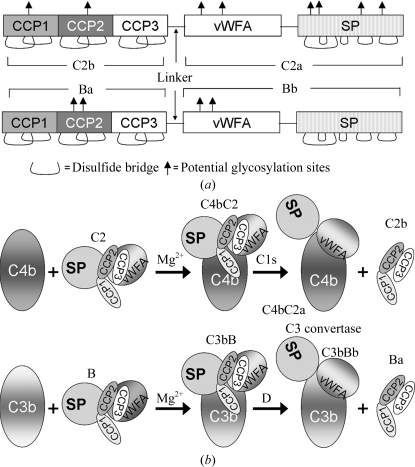
The second component of human complement (C2) is a 100 kDa glycoprotein (Fig. 1 ▶ a) which participates in the classical and lectin pathways of complement activation by providing a catalytic subunit to C3/C5 convertases. Electron-microscopic studies have suggested that C2 is comprised of three lobes (Smith et al., 1984 ▶). Primary-sequence alignment (Bentley, 1986 ▶; Horiuchi et al., 1989 ▶) with the homologous factor B revealed that the N-terminal lobe is made up of three complement control protein (CCP) modules, also known as short consensus repeats (SCR) or sushi-domain repeats (Fig. 1 ▶ a), the middle lobe is a typical von Willebrand factor type A (vWFA) domain containing a metal-ion-dependent adhesion site (MIDAS) similar to that present in the I domains of integrins (Kamata et al., 1999 ▶) and the C-terminal lobe is an atypical chymotrypsin-like serine protease (SP) that displays trypsin-like specificity (Arlaud et al., 1998 ▶). C2 binds to an activating surface-bound C4b (in the presence of Mg2+) to form a C4bC2 complex, which is then cleaved by activated C1s [or mannan-binding lectin-associated serine protease 2 (MASP2) in the lectin pathway]. Cleavage of C4b bound to C2 by C1s or MASP2 yields two fragments: a larger 70 kDa fragment C2a (vWFA + SP domains), which remains attached to C4b to form C3 convertase C4bC2a, and a smaller 30 kDa N-terminal fragment C2b (CCP1–3 modules) that is released into the fluid phase (Fig. 1 ▶ b). C2 shares structural and functional features with factor B (Fig. 1 ▶) of the alternative pathway, which provides the catalytic subunit to C3 convertase C3bBb. Analogously, factor B binds to C3b to form the C3bB complex, which is then cleaved by factor D, resulting in C3 convertase C3bBb and the smaller N-terminal fragment Ba (Fig. 1 ▶ b).
Figure 1.
(a) Domain organization of the homologous proteins C2 and factor B of human complement. (b) Cartoon representation of classical and alternative pathway C3 convertase formation. Abbreviations used: CCP, complement control protein; vWFA, von Willebrand factor type A domain; SP, serine protease domain; C2b and Ba, the N-terminal fragments of C2 and factor B that are made up of CCP modules and released upon formation of the convertases C4bC2a and C3bBb, respectively; C2a and Bb, the C-terminal fragments of C2 and factor B that remain associated with cofactors C4b and C3b in the formation of the C3 convertases C4bC2a and C3bBb, respectively; C4b and C3b, the active fragments of C4 and C3, respectively.
CCP modules are common structural motifs of receptors, enzymes and regulatory proteins of the complement system and many noncomplement proteins. Although all CCP modules share a common tertiary structure, they play diverse biological functions. Some mediate specific ligand recognition and some play a structural role. For example, complement receptor type 1 (CR1) and type 2 (CR2), factor H and C4b-binding protein (C4BP), membrane cofactor protein (MCP), decay accelerating factor (DAF), C1s, C1r and mannan-binding lectin-associated serine proteases (MASPs) carry varying numbers of CCP modules. These globular units contain approximately 60 residues and fold into a compact six- to eight-stranded β-sheet structure built around four invariant disulfide-bonded cysteine residues. Disulfide bonds are seen between the first and third (Cys1–Cys3) and the second and fourth (Cys2–Cys4) cysteine residues. The residues conserved around these cysteines include highly conserved Trp, Gly and Pro residues and some hydrophobic residues (Norman et al., 1991 ▶). Neighboring modules are covalently attached by poorly conserved linkers. The relative orientations of neighboring modules differ from one module pair to another (Barlow et al., 1993 ▶; Lehtinen et al., 2004 ▶); however, in most cases the CCP modules are connected linearly (head-to-tail) like beads on a string (Gilbert et al., 2005 ▶, 2006 ▶).
Studies have shown that at least one binding site present in C2b is important for C4b binding in C3 convertase formation (Nagasawa & Stroud, 1977 ▶; Xu & Volanakis, 1997 ▶). In addition, the MIDAS present in the vWFA domain of C2a is involved in C4b binding (Horiuchi et al., 1991 ▶) once the C3 convertase has been formed. Analogously, affinity between Ba and C3b has been indicated in C3 convertase formation by the alternative pathway (Pryzdial & Isenman, 1987 ▶; Hourcade et al., 1995 ▶; Ueda et al., 1987 ▶). It has also been revealed that the binding site in C2b is Mg2+-independent, reacts slowly and forms a stable interaction, whereas the MIDAS binding site in C2a is Mg2+-dependent and reacts quickly but the interaction is not stable (Laich & Sim, 2001 ▶). The role of C2b after its release is not clearly known, although one study has suggested that the C-terminal region of C2b enhances vascular permeability in humans and guinea pigs, leading to edema (Strang et al., 1988 ▶). The full-length factor B structure detailing the interactions between the Ba and Bb segments is available and the authors have made postulations regarding the possible conformational changes that the Ba and Bb segments undergo upon binding to C3b (Milder et al., 2007 ▶). The crystal structure of a BbC428–C435 mutant also detailed the possible conformational changes in Bb upon binding to the cofactor C3b (Ponnuraj et al., 2004 ▶). The crystal structure of C2a has been determined (Milder et al., 2006 ▶; Krishnan et al., 2007 ▶) and here we present the crystal structure of C2b at 1.8 Å resolution. With the help of the available crystal structures of factor B, the BbC428–C435 mutant, C2a and the present C2b, we propose a model for full-length C2 and suggest the conformational changes that C2, C2a and C2b might undergo during C3 convertase C4bC2a formation.
2. Materials and methods
2.1. Expression and purification
Full-length C2 was expressed and purified using the protocol described previously (Krishnan et al., 2007 ▶). Briefly, full-length C2 cDNA (Horiuchi et al., 1989 ▶) was cloned into the baculovirus expression vector pACgp67A (BD Biosciences Pharmingen, San Diego, California, USA) and co-transfected with BD Baculogold Bright linearized baculovirus DNA into sf9 insect cells. A C241A mutation had been introduced into the cDNA to avoid the formation of undesired disulfide bonds and protein aggregation. Previously, we have shown that the C241A mutant behaved similarly to the wild-type enzyme with slightly elevated hemolytic activity (Horiuchi et al., 1991 ▶). High-titer stocks were produced in sf9 insect cells and used to infect High Five insect cells (Invitrogen, Carlsbad, California, USA) for protein expression. Media from the infection were harvested on day 5 and C2 was purified by successive chromatography using S Sepharose, Heparin HT and Mono S columns on an FPLC system (ÄKTA Purifier; GE Healthcare, Piscataway, New Jersey, USA). C2b was obtained by proteolysis of C2 by C1s. Purified C2 in 10 mM HEPES pH 7.4, 120 mM NaCl was incubated with trace amounts of activated C1s at 310 K for 60 min. C2a and C2b fragments were separated and C2b was further purified by successive chromatographic techniques (Nagasawa & Stroud, 1977 ▶).
2.2. Crystallization
Crystallization was carried out by the hanging-drop vapor-diffusion method using purified C2b (in 10 mM HEPES, 120 mM NaCl pH 7.4) at 277 K. A droplet containing 2 µl C2b (12 mg ml−1), 1.6 µl well solution [18%(w/v) polyethylene glycol 3350, 0.22 M sodium chloride] and 0.4 µl 0.1 M betaine hydrochloride was equilibrated against 1 ml well solution. Long and thick rod-shaped crystals grew in 4–7 d.
2.3. Data collection
C2b native diffraction data were collected using a Rigaku R-AXIS IV imaging-plate detector on an in-house Rigaku rotating-anode X-ray generator operating at 100 mA and 50 kV. Ethylene glycol [20%(v/v) in stabilizing solution consisting of 20%(w/v) PEG 3350 in well solution] was used as a cryoprotectant and crystals were flash-frozen in a nitrogen stream at 100 K. The unit-cell parameters, systematic absences and Matthews coefficient (V M) calculations suggested the space group to be P31 with one molecule per asymmetric unit. The data were processed and scaled using the program d*TREK (Pflugrath, 1999 ▶). The crystallographic data statistics are presented in Table 1 ▶.
Table 1. Crystallographic data for native C2b crystal.
Values in parentheses are for the outermost resolution shell.
| Space group | P31 |
| Unit-cell parameters (Å) | a = b = 60.09, c = 61.69 |
| Resolution (Å) | 40.0–1.8 (1.86–1.80) |
| Rmerge† (%) | 3.3 (23.7) |
| Average redundancy | 4.36 (4.15) |
| Unique reflections | 23095 |
| Completeness (%) | 100.0 (100.0) |
| χ2 | 0.99 (1.33) |
| 〈I/σ(I)〉 | 21.0 (5.1) |
R
merge = 
 , where Ii(hkl) is the ith observation for unique hkl and 〈I(hkl)〉 is the mean intensity for unique hkl.
2.4. Structure determination, model building and refinement
Initial phases for the C2b diffraction data were obtained by molecular-replacement methods using the homologous structure of the Ba fragment of factor B (Milder et al., 2007 ▶; PDB code 2ok5) as a search model with CNS (Brünger et al., 1998 ▶). A polyalanine model of the three CCP domains of Ba was generated for the initial search. A clear molecular-replacement solution was obtained in the cross-rotation and subsequent translation-function searches. Molecular-replacement searches using Phaser (McCoy et al., 2005 ▶) with individual domains also gave the same solution. Chain tracing and model building were carried out with the help of the program Coot (Emsley & Cowtan, 2004 ▶). Several rounds of model building and final refinement with REFMAC (Murshudov et al., 1997 ▶) and the addition of water molecules in the final stages gave a final R work of 0.21% and an R free of 0.24%. The refinement statistics of the C2b structure are listed in Table 2 ▶. The final C2b model was checked using PROCHECK (Morris et al., 1992 ▶).
Table 2. Refinement statistics for the C2b structure.
| Resolution range (Å) | 40–1.8 |
| Rwork/Rfree† (%) | 21.4/23.9 |
| Average B value (Å2) | 23.3 |
| R.m.s.d. for bonds (Å) | 0.011 |
| R.m.s.d. for angles (°) | 1.243 |
| No. of non-H atoms | 1612 |
| No. of water molecules | 197 |
| Ramachandran plot (favored/allowed) (%) | 92.3/7.7 |
| PDB code | 3erb |
R
work = 
 , where F
o and F
c are measured and calculated structure factors, respectively. R
free was calculated using 5% of data excluded from refinement.
3. Results and discussion
3.1. Overall structure of C2b
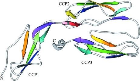
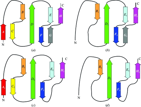
The three-dimensional structure of the C2b molecule is shown in Fig. 2 ▶. The overall dimensions of the molecule are 70 × 35 × 25 Å and it consists of 223 amino acids folded into three CCP domains (CCP1, CCP2 and CCP3) in a triad arrangement (Fig. 2 ▶). The overall fold of each CCP domain in C2b resembles those of other CCP domains observed in complement proteins (Uhrinova et al., 2003 ▶; Smith et al., 2002 ▶; Milder et al., 2007 ▶). These three CCP domains are similar in secondary structure (Figs. 3 ▶ and 4 ▶) as reflected by the root-mean-square deviations (r.m.s.d.s; Fig. 4 ▶), although there is no strong sequence identity between them (<28%). Each domain has an elongated shape with approximate dimensions of 40 × 20 × 20 Å and is composed of five segments that run back or forth to form a β-sandwich fold that surrounds a hydrophobic core. Parts of these segments can be classified as β-strands (labeled A–H in Fig. 3 ▶ a), which constitute ∼50% of the structure (Smith et al., 2002 ▶; Henderson et al., 2001 ▶). Two sides of the β-sandwich fold are represented by a three-stranded antiparallel β-sheet (BDF) and a small two-stranded antiparallel β-sheet (EH). A ‘β-bulge’ (between β-strands E and F) and a hypervariable (hv) region (between β-strands B and C), which is often suggested as a likely interaction site and is commonly observed in CCP modules, are also present in the C2b CCP domains. The N- and C-termini lie at opposite ends of the long axis of each CCP domain (Barlow et al., 1993 ▶).
Figure 2.
Overall ribbon representation of the C2b structure, which is made up of three CCP domains: CCP1, CCP2 and CCP3. Individual CCP domains are labeled and successive β-strands are represented in rainbow colors.
Figure 3.
Topology representation of individual CCP domains of C2b. Successive individual β-strands are labeled A–H and are colored as in Fig. 2 ▶. Topology representations are shown for (a) a typical CCP domain and the individual CCP domains of C2b: (b) CCP1, (c) CCP2 and (d) CCP3.
Figure 4.
Superposition of the three CCP modules of C2b. CCP1 is depicted in green, CCP2 in yellow and CCP3 in red.
CCP1 consists of 65 residues (2–66 in mature C2 numbering) with a buried hydrophobic core (Trp50, Pro5, Trp21, Leu27, Tyr29, Pro37 and Ile10) and two cysteine bridges (Cys4–Cys44 and Cys31–Cys64). The locations of β-strands may be inferred as B 1, 14TFTL17; D 1, 26LLTYS30; E 1, 35LYPS38; F 1, 41SRLC44; G 1, 50WQ51; H 1, 63VCKP66. The additional strand G 1 is part of a four-stranded antiparallel β-sheet B 1 D 1 F 1 G 1 that replaces the common BDF β-sheet. The loop (Thr52–Ala62) joining strands G 1 and H 1 is disordered.
CCP2 consists of 60 residues (67–126) with a buried hydrophobic core (Trp117, Pro70, Tyr87, Val93, Phe95, Leu103 and Phe75) and two cysteine bridges (Cys69–Cys111 and Cys97–Cys124). This module is made up of β-strands A 2 (68RCP70), B 2 (78GIYT81), C 2 (86SYP88), D 2 (92NVSFEC97), E 2 (102ILR104), F 2 (108VRQ110) and H 2 (123VCD125). Strands A 2 and C 2 form a short β-sheet at the head of CCP2 in addition to the common three-stranded BDF and two-stranded EH β-sandwich arrangement.
CCP3 consists of 58 residues (127–186) with a buried hydrophobic core (Trp177, Pro132, Phe147, Val158, Tyr155, Leu163 and Ile136) and two cysteine bridges (Cys131–Cys171 and Cys157–Cys184). It is made up of β-strands B 3 (140AVRT143), D 3 (152KVRYRC157), E 3 (162VLT164), F 3 (168ERE170) and H 3 (183ICR185). In all three CCP modules, β-strand H extends one residue beyond the fourth cysteine residue, thus reducing the degree of freedom of the following linkers. In CCP2, the hv (BC) loop projects perpendicularly to the long axis of the module more than in the other two CCPs owing to an insertion. A tightly packed antiparallel dimer is formed by the CCP2 and CCP3 modules, while CCP1 caps the dimer as in Ba (Milder et al., 2007 ▶). The triad arrangement produces a small hydrophobic core at the triad center (Tyr36, Val67, Val89 and Phe192). CCP1 and CCP2 are connected via a four-residue linker (Lys64-Pro66-Val67-Arg68), while CCP2 and CCP3 are connected by a six-residue linker (Asp124-Asn126-Gly127-Ala128-Gly129-His130). Unlike the factor B structure (Milder et al., 2007 ▶), the long linker (Pro187–Arg223) that connects CCP3 to the vWFA domain of C2 is disordered and density is only observed for the N-terminal part of the linker.
The β-bulge (E 1 F 1) loop of CCP1 is one residue shorter than in the other CCPs. The F 1 H 1 region of CCP1 is disordered and longer than the corresponding regions of CCP2 and CCP3 owing to a seven-residue insertion in the G 1 H 1 loop (Fig. 5 ▶). This long insertion is not common in other CCPs [e.g. VCP (Murthy et al., 2001 ▶) and fh15-16 (Barlow et al., 1993 ▶)]. CCP3 carries a 310-helix at the C-terminal end of the vWFA linker. CCP2 and CCP3 are more similar to each other (r.m.s.d. of 1.0 Å for 50 common Cα atoms) than to CCP1 (r.m.s.d.s of 1.6 Å for 47 common Cα atoms with CCP2 and 1.5 Å for 47 common Cα atoms with CCP3). Only CCP2 has an additional short β-sheet (A 2 C 2) at its head. In most crystal structures of multiple CCP modules, the adjacent CCP domains form an elongated head-to-tail arrangement that makes them resemble beads on a string, but CCP2 and CCP3 in C2b display an unusual side-to-side conformation. The linker between CCP2 and CCP3 is six residues in length, allowing an unusual inter-domain orientation between them, whereas the linker between CCP1 and CCP2 is four residues long. Side-to-side packing in a ‘V’ arrangement has been observed for two consecutive CCP modules of receptor CR2 (Szakonyi et al., 2001 ▶; Prota et al., 2002 ▶), but the side-by-side arrangement of CCP2 and CCP3 in C2b is nearly parallel and tight. The orientation of each CCP module with respect to its neighbor can be conveniently described by measuring its tilt, twist and skew angles (Bork et al., 1996 ▶; Lehtinen et al., 2004 ▶; Barlow et al., 1993 ▶) and the measured values are summarized in Table 3 ▶.
Figure 5.
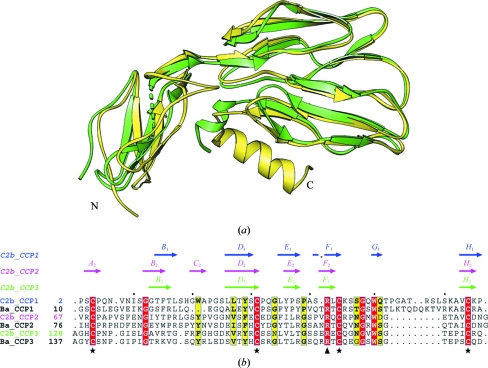
Comparison of the N-terminal fragments of C2 and factor B. (a) Superposition of the Ba segment of factor B (yellow) and C2b (green). (b) Structure-based sequence alignment (plotted with ESPript) of the CCPs of C2b and Ba. A schematic summary of the secondary structure (labeled arrows) of β-strands is shown at the top as determined for the CCPs of C2b using the program DSSP (Kabsch & Sander, 1983 ▶). The invariant Cys and uncommon highly conserved Arg residues are marked with stars and triangles at the bottom.
Table 3. Tilt, twist and skew angles (°) between adjacent CCP domains of C2b and Ba.
Tilt, twist and skew angles were calculated using the program mod22 using a vector between the principal axis of the inertia tensor and the Cα atom of Trp in each module. Module boundaries were defined by Cys1 and Cys4.
| CCP pair | Tilt | Twist | Skew |
|---|---|---|---|
| C2b CCP1–CCP2 | 86.3 | 141.3 | 106.6 |
| C2b CCP2–CCP3 | 199.6 | 186.2 | 312.0 |
| C2b CCP1–CCP3 | 294.4 | 218.1 | 102.2 |
| Ba CCP1–CCP2 | 93.8 | 138.8 | 124.2 |
| Ba CCP2–CCP3 | 189.9 | 171.2 | 307.1 |
| Ba CCP1–CCP3 | 294.5 | 230.3 | 107.1 |
C2b is known to have two potential N-linked glycosylation sites (Bentley, 1986 ▶), one in the CCP1 domain (Asn9) and the other in the CCP2 domain (Asn92). We observed weak and bulky electron densities at these sites, suggesting that these residues might be glycosylated in the recombinant C2b.
3.2. Comparison with the Ba structure
Since the crystal structure of the Ba domain is only available as part of full-length factor B, comparisons of C2b were carried out using the Ba region (Milder et al., 2007 ▶). The overall domain arrangement of the three CCP modules of C2b is very similar to that in Ba except for a small rotation of the CCP1 module (Fig. 5 ▶ and Table 3 ▶). Superposition of the CCP modules of C2b on those of Ba yielded an r.m.s. deviation of 1.6 Å for 156 common Cα atoms. The hv (B 1 C 1) loop (His19–Ser25) of C2b is four residues longer than that of Ba and is in an extended conformation at the N-terminal region, whereas Ba displays a short 310-helix. The β-bulge (E 1 F 1) loop (Pro37–Ala40) of C2b is one residue shorter than that of Ba. The G 1 H 1 loop (Thr52–Ala62) of C2b is disordered and is not seen in the electron density, whereas in Ba it forms an extended loop towards the tail of the CCP3 module. The presence of the extra G 1 strand in C2b results in a four-stranded β-sheet (B 1 D 1 F 1 G 1), whereas the corresponding region of Ba forms an extended loop. Another variation is seen in the long linker (Pro187–Arg223) that connects CCP3 to the vWFA domain. In C2b it is disordered with a short 310-helix (Pro187–Asp191), while in Ba this linker forms an α-helix (αL, 202–213) with a short loop (198–201) at the N-terminal end and a long loop (214–242) at the C-terminal end (Milder et al., 2007 ▶). This linker is stabilized by the vWFA and SP domains in the factor B structure. There is a conserved arginine residue in all CCPs of C2b (Arg42, Arg109 and Arg169) and Ba (Arg49, Arg118 and Arg178) near the third cysteine in addition to the conserved tryptophan (Trp50, Trp117 and Trp177), glycine (Gly48, Gly115 and Gly175), and proline (Pro5, Pro70 and Pro132) residues of C2b (Fig. 5 ▶ b).
3.3. Domain interface
The total buried surface area between CCP1 and CCP2 of C2b was calculated to be 382 Å2; that between CCP1 and CCP3 was 292 Å2 and that between CCP2 and CCP3 was 1598 Å2. The CCP3–vWFA linker was also included in the analysis. The buried surface areas are comparable with those observed in Ba (see Table 4 ▶), except for a small increase between CCP1 and CCP3 of Ba owing to the extension of the GH loop of CCP1 towards the CCP3 tail.
Table 4. Buried surface area (Å2) between adjacent CCP domains of C2b and Ba.
| CCP pair | CCP1–CCP2 | CCP2–CCP3 | CCP1–CCP3 |
|---|---|---|---|
| C2b | 383 | 1598 | 292 |
| Ba | 323 | 1620 | 464 |
Analysis of the inter-domain contacts between CCP-domain pairs in the available structures has shown that the contacts arise from four sequence stretches (Lehtinen et al., 2004 ▶): the DE loop of the N-terminal CCP (N#1), the CD loop of the C-terminal CCP (C#1), the FG loop of the C-terminal CCP (C#2) and the linker joining the CCPs. In C2b the interface contacts between CCP1 and CCP2 (about eight contacts <4 Å) arise from four stretches: N#1 (Gln33 and Gly34), C#1 (Val89), C#2 (Pro113) and the linker (Val67). However, with the exception of the linker, the corresponding stretches did not contribute to the interface between CCP2 and CCP3, which is constituted of a total of 36 residues (18 residues from each domain), seven of which are charged. The residues of the two domains make 30 contacts measuring less than 4 Å, including a salt bridge (Glu76–Arg142) and hydrogen bonds. These contacts arise from nearly all segments of the CCP2 and CCP3 modules. CCP1 shares only a small interface with CCP3 (three contacts <4 Å) that arises from strand E 1, the D 1 E 1 loop of CCP1 and the C-terminal 310-helix of CCP3. The CCP2 and CCP3 interface from the tight side-to-side packing seen in C2b and Ba is very unusual compared with other known structures that contain CCP modules as found in the CCP-module database (http://www.bionmr.chem.ed.ac.uk/bionmr/public_html/ccp-db.html).
3.4. C2 model
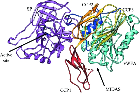
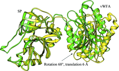
The r.m.s.d. between the C2a and Bb structures is 2.0 Å (for 351 Cα atoms) and the buried surface areas and relative orientations between the respective vWFA and SP domains are comparable, suggesting that the loss of N-terminal segments results in conformationally similar factor B and C2 remnants. If we examine the association of Ba with Bb, specifically with the vWFA domain of the latter, there are no apparent strong interactions between them except for the interaction between the αL helix of the CCP3–vWFA linker segment and the α7 helix of the vWFA domain (Milder et al., 2007 ▶). However, the relative orientation of the SP and vWFA domains differs significantly between the factor B and Bb structures, suggesting that the loss of the αL–α7 helix association upon cleavage of Ba allows translation of the vWFA domain by 6.0 Å and rotation by 68° away from the SP domain (Milder et al., 2007 ▶; Ponnuraj et al., 2004 ▶). The recombinant C2b was expressed until the end of the CCP3–vWFA linker and used for crystallization. However, the linker may be flexible owing to the loss of its association with the α7 helix, as it does not appear in the electron-density map. We built a model of full-length C2 (Fig. 6 ▶) using the current C2b and C2a crystal structures (Krishnan et al., 2007 ▶), in which we retained the observed domain arrangement and the inter-domain linker (CCP3–vWFA, vWFA–SP) positions of full-length factor B (Milder et al., 2007 ▶). The model was idealized with the help of the REFMAC program (Murshudov et al., 1997 ▶) and its quality was examined using a Ramachandran plot. In the C2 model, the side chain of the scissile-bond residue Arg223, which is present at the C-terminal end of the CCP3–vWFA linker, occupies the position of Arg234 in factor B. The Arg234 side chain in factor B is bound to both the αL and α7 helices via hydrogen bonds to Glu207 and Glu446, respectively. However, in C2 Arg223 is not stabilized by hydrogen bonds since the corresponding Glu residues of αL and α7 are absent, having been replaced by Pro198 and Ser436, respectively. Only the Ser436 hydroxyl contacts the N∊ atom of the Arg223 side chain in C2 and this may partially explain the reasons for the ready cleavage of free C2 into C2a and C2b by C1s or other proteases, in contrast to factor B.
Figure 6.
Model of full-length C2 in ribbon representation. The N-terminal CCP1 (red), CCP2 (gold), CCP3 (yellow), CCP3–vWFA linker (blue), vWFA domain (cyan) and SP domain (magenta) are represented and the MIDAS and SP catalytic site are indicated with arrows.
3.5. Implications for C4b binding
The current understanding of classical/lectin-pathway convertase assembly is that the initial binding of C2 to active surface-bound C4b is mediated by two low-affinity sites, one on C2b (Xu & Volanakis, 1997 ▶) and the other on the vWFA domain, through the MIDAS motif (Horiuchi et al., 1991 ▶). The subsequent cleavage by C1s or MASP2 causes a transient conformational change in the latter site, leading to an increased binding avidity for C4b, sequestration of Mg2+ and the expression of proteolytic activity for C3 (Arlaud et al., 1998 ▶). Understanding the nature of the conformational changes in the C4b-bound vWFA domain of C2a has mainly been influenced by studies on the homologous domains of integrins, variously termed as I or A domains, and also from structural studies of the BbC428–C435 mutant (Ponnuraj et al., 2004 ▶).
The C-terminal region of the CCP3–vWFA linker observed in C2a structures (Krishnan et al., 2007 ▶; Milder et al., 2006 ▶) seems to be positioned to control α7-helix movement in the interface of the vWFA and SP domains, as it partially occupies the shifted α7-helix position seen in the engineered Bb mutant that is in the activated ‘open’ confirmation (Emsley et al., 2000 ▶). In the factor B structure, helix αL of this linker is squeezed between the α7 helix of vWFA and the SP domain (Milder et al., 2007 ▶). Arg234 present in the CCP3–vWFA linker is linked to the α7 and αL helices by hydrogen bonds; the Arg234–Lys235 scissile bond is thus protected from proteolysis by factor D. Reshuffling of these helices (α7 and αL) owing to C3b binding through MIDAS in the vWFA domain and the consequent shifting of the α7 helix away from MIDAS probably breaks the Arg234 side-chain hydrogen bonds and makes the scissile bond Arg234–Lys235 accessible. However, the conformational changes required to activate the ‘zymogen-like’ factor D (Volanakis & Narayana, 1996 ▶), probably provided by the released CCP3–vWFA linker and/or its surroundings, upon C3b binding adds another step of complexity to C3 convertase formation in the alternative pathway activation. A similar rearrangement, but qualitatively different owing to weaker interactions between the CCP3–vWFA linker and the rest of the domains of C2, could set apart the classical pathway C3 convertase formation.
The presence of the C4b-binding site within the CCP modules of C2b was initially suggested based on the observation that C2b remained noncovalently bound to Sepharose-C4b beads after C1s cleavage (Nagasawa & Stroud, 1977 ▶). This finding was further supported by the demonstration of a C2bC4b complex in the fluid phase in the presence of Mg2+ and under low ionic strength conditions (Kerr, 1980 ▶). It was subsequently shown that 3A3.3, a monoclonal antibody with specificity for C2b, inhibited the binding of C2 to C4b (Oglesby et al., 1988 ▶), indicating the presence of C4b-binding site(s) on C2b. The contribution of the three CCP modules to C4bC2 complex formation was investigated by the construction of FB–C2 chimeras by substituting CCP modules of FB for the corresponding modules of C2. The results of this study suggested that all three CCPs contributed to the interaction (Xu & Volanakis, 1997 ▶). It was also shown that C2b accelerates decay-dissociation of the C3 convertase and acts as a feedback inhibitor on the activation of the classical pathway of complement system (Nagasawa et al., 1985 ▶). A surface plasmon resonance study has indicated the presence of at least two binding sites on C2. An Mg2+-independent binding site in C2b was shown to react slowly but to form a stable interaction, while an Mg2+-dependent site on C2a (MIDAS) reacts rapidly but yields an interaction that is not very stable (Laich & Sim, 2001 ▶). In similar studies, purified Ba was able to inhibit C3bB complex formation (Pryzdial & Isenman, 1987 ▶).
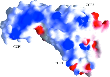
It has been shown that the acidic residues within the N-terminal segment of C4 (744EED and 749DEDD) and C3 (730DE and 736EE) are important for the binding of C2 and factor B, respectively (Pan et al., 2000 ▶). In addition, electron micrographs of the C4bC2a complex show that C2a is attached to C4b through only one of its two domains (Smith et al., 1984 ▶). We have observed the presence of a positively charged region on loop 2 of the SP domain (Krishnan et al., 2007 ▶), but a single site on the vWFA domain that includes the MIDAS motif was suggested as the interaction point (Horiuchi et al., 1991 ▶). However, the region around the MIDAS motif is strongly electronegative, while several Lys and Arg residues are observed in the C2b structure that contribute to the positive charge on its surface (Fig. 7 ▶), suggesting that perhaps the CCP modules participate through ionic interactions with C4b. As seen in the surface representation, large patches of positive charges are present on the surface of CCP1 (Lys45, Arg42 and Lys65), CCP2 (Arg68, hv loop Arg83) and CCP3 (Lys152, Arg154, Arg156 and Arg146). In the C2 model there are two positive sites on C2b: one on CCP2 (Arg112) interacts with the SP domain and the other on CCP3 (Arg185) interacts with the vWFA domain. Similar types of positive patches are also present on Ba, but there are more on CCP1 (Lys20, Lys61, Lyst66, Arg69, Lys70 and Arg74) than CCP2 (Arg80 and Arg92) and CCP3 (Arg150, Arg157, Arg168 and Arg177). However, there are few positive patches on the interface of Ba and Bb.
Figure 7.
Electrostatic surface representation of C2b. The surface-charge distribution was calculated using GRASP (Nicholls et al., 1991 ▶). Positively charged regions are represented in blue, negatively charged regions are represented in red and both polar and nonpolar regions are represented in white.
Another possible site (933–942) consisting of acidic clusters has been located on the CUB domain of C3b for factor B binding (O’Keefe et al., 1988 ▶). Therefore, positively charged C2b can bind to one of these negatively charged sites (α′NT or CUBg) on C4b to initiate C4b–C2 complex formation. However, further studies are needed to identify the exact residues of C2b that are involved in the initial interactions with C4b and for this the crystal structures of C4bC2 and/or C4bC2a need to be elucidated.
4. Conclusions
CCP modules are structural domains that are abundant in complement proteins in numbers of up to 30. High-resolution crystal and solution structures are available for individual and clusters of up to five CCP modules. Of the 45 or so CCP module(s) with coordinates deposited in the PDB, only two crystal structures of complement receptor type 2 (CR2) display a side-by-side V-shaped arrangement (Szakonyi et al., 2001 ▶; Prota et al., 2002 ▶). Solution studies also suggest that CR2 displays an open ‘V’ arrangement (Gilbert et al., 2005 ▶, 2006 ▶). All others display linear arrangements like beads on a string. Two of the three CCP modules of C2b are arranged in a distinct almost side-by-side arrangement. Comparison of the C2 model built using the crystal structures of C2a and C2b and the homologous factor B reveals similar weak associations between the N-terminal C2b and Ba domains and the C-terminal C2a and Bb domains, respectively. One significant conclusion drawn from this structural study is that once released upon C3 convertase formation, the N-terminal segments (C2b and Ba), in light of extensive interactions emanating from salt bridges, polar and hydrophobic interactions between CCP2 and CCP3, may not undergo conformational changes. This conclusion is further supported by the resemblance of the crystal structure of C2b, which is obtained from C2 by C1s cleavage, to the Ba part of the intact factor B structure. However, solution scattering studies may help to validate the conclusions regarding the lack of conformational changes in C2b upon cleavage of C2 by C1s.
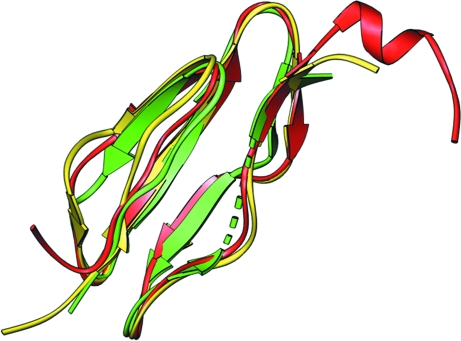
The association of N-terminal small (Ba and C2b) and C-terminal large (Bb and C2a) domains is weak both in factor B and C2 and they are held in place predominantly by the association of the CCP3–vWFA linker with the C-terminal helix α7 of the vWFA domain. This observation supports our previous conclusion (Ponnuraj et al., 2004 ▶) that the conformational changes induced by the cofactor (C3b and C4b) of the MIDAS motif of the vWFA domains of factor B and C2, respectively, are not transmitted to the respective SP domains. Instead, they serve to facilitate the rearrangement of the CCP3–vWFA linker, making it amenable to cleavage by factor D or C1s, respectively. We can further conclude that the cofactor-induced conformational changes facilitate the disruption of the CCP3–vWFA linker and α7-helix association, owing to a large 10 Å shift in the α7 helix, leading to the cleavage of N-terminal domains (C2b and Ba) and translation (by ∼6.0 Å) coupled to rotation (∼68°) of the SP and vWFA domains of cofactor-attached C2a and Bb, respectively (Fig. 8 ▶). The latter conclusion may also support the observation that the dissociated C2a and Bb segments cannot associate again with C4b and C3b, respectively, as they are arranged differently compared with the conformations seen in C2 and factor B. It may also support the initial requirement of weak C2b and Ba association with C4b and C3b for the formation of the C4bC2 and C3bB complexes, respectively.
Figure 8.
Possible conformational changes in the C2a fragment upon loss of C2b. The translation and rotation of the vWFA domain from the SP domain before (green) and after (yellow) the loss of association with the C2b segment and its CCP domains is shown.
Supplementary Material
PDB reference: C2b, 3erb, r3erbsf
Acknowledgments
The project was supported in part by NIH grant AI1064815 to SVLN. We thank Dr Dinesh C. Soares for his help in tilt, twist and skew angle calculations.
References
- Arlaud, G. J., Volanakis, J. E., Thielens, N. M., Narayana, S. V., Rossi, V. & Xu, Y. (1998). Adv. Immunol.69, 249–307. [PubMed]
- Barlow, P. N., Steinkasserer, A., Norman, D. G., Kieffer, B., Wiles, A. P., Sim, R. B. & Campbell, I. D. (1993). J. Mol. Biol.232, 268–284. [DOI] [PubMed]
- Bentley, D. R. (1986). Biochem. J.239, 339–345. [DOI] [PMC free article] [PubMed]
- Bork, P., Downing, A. K., Kieffer, B. & Campbell, I. D. (1996). Q. Rev. Biophys.29, 119–167. [DOI] [PubMed]
- Brünger, A. T., Adams, P. D., Clore, G. M., DeLano, W. L., Gros, P., Grosse-Kunstleve, R. W., Jiang, J.-S., Kuszewski, J., Nilges, M., Pannu, N. S., Read, R. J., Rice, L. M., Simonson, T. & Warren, G. L. (1998). Acta Cryst. D54, 905–921. [DOI] [PubMed]
- Emsley, J., Knight, C. G., Farndale, R. W., Barnes, M. J. & Liddington, R. C. (2000). Cell, 101, 47–56. [DOI] [PubMed]
- Emsley, P. & Cowtan, K. (2004). Acta Cryst. D60, 2126–2132. [DOI] [PubMed]
- Gilbert, H. E., Aslam, M., Guthridge, J. M., Holers, V. M. & Perkins, S. J. (2006). J. Mol. Biol.356, 397–412. [DOI] [PubMed]
- Gilbert, H. E., Eaton, J. T., Hannan, J. P., Holers, V. M. & Perkins, S. J. (2005). J. Mol. Biol.346, 859–873. [DOI] [PubMed]
- Henderson, C. E., Bromek, K., Mullin, N. P., Smith, B. O., Uhrin, D. & Barlow, P. N. (2001). J. Mol. Biol.307, 323–339. [DOI] [PubMed]
- Horiuchi, T., Macon, K. J., Engler, J. A. & Volanakis, J. E. (1991). J. Immunol.147, 584–589. [PubMed]
- Horiuchi, T., Macon, K. J., Kidd, V. J. & Volanakis, J. E. (1989). J. Immunol.142, 2105–2111. [PubMed]
- Hourcade, D. E., Wagner, L. M. & Oglesby, T. J. (1995). J. Biol. Chem.270, 19716–19722. [DOI] [PubMed]
- Kabsch, W. & Sander, C. (1983). Biopolymers, 22, 2577–2637. [DOI] [PubMed]
- Kamata, T., Liddington, R. C. & Takada, Y. (1999). J. Biol. Chem.274, 32108–32111. [DOI] [PubMed]
- Kerr, M. A. (1980). Biochem. J.189, 173–181. [DOI] [PMC free article] [PubMed]
- Krishnan, V., Xu, Y., Macon, K., Volanakis, J. E. & Narayana, S. V. (2007). J. Mol. Biol.367, 224–233. [DOI] [PMC free article] [PubMed]
- Laich, A. & Sim, R. B. (2001). Biochim. Biophys. Acta, 1544, 96–112. [DOI] [PubMed]
- Lehtinen, M. J., Meri, S. & Jokiranta, T. S. (2004). J. Mol. Biol.344, 1385–1396. [DOI] [PubMed]
- McCoy, A. J., Grosse-Kunstleve, R. W., Storoni, L. C. & Read, R. J. (2005). Acta Cryst. D61, 458–464. [DOI] [PubMed]
- Milder, F. J., Gomes, L., Schouten, A., Janssen, B. J., Huizinga, E. G., Romijn, R. A., Hemrika, W., Roos, A., Daha, M. R. & Gros, P. (2007). Nature Struct. Mol. Biol.14, 224–228. [DOI] [PubMed]
- Milder, F. J., Raaijmakers, H. C., Vandeputte, M. D., Schouten, A., Huizinga, E. G., Romijn, R. A., Hemrika, W., Roos, A., Daha, M. R. & Gros, P. (2006). Structure, 14, 1587–1597. [DOI] [PubMed]
- Morris, A. L., MacArthur, M. W., Hutchinson, E. G. & Thornton, J. M. (1992). Proteins, 12, 345–364. [DOI] [PubMed]
- Murshudov, G. N., Vagin, A. A. & Dodson, E. J. (1997). Acta Cryst. D53, 240–255. [DOI] [PubMed]
- Murthy, K. H., Smith, S. A., Ganesh, V. K., Judge, K. W., Mullin, N., Barlow, P. N., Ogata, C. M. & Kotwal, G. J. (2001). Cell, 104, 301–311. [DOI] [PubMed]
- Nagasawa, S., Kobayashi, C., Maki-Suzuki, T., Yamashita, N. & Koyama, J. (1985). J. Biochem.97, 493–499. [DOI] [PubMed]
- Nagasawa, S. & Stroud, R. M. (1977). Proc. Natl Acad. Sci. USA, 74, 2998–3001. [DOI] [PMC free article] [PubMed]
- Nicholls, A., Sharp, K. A. & Honig, B. (1991). Proteins, 11, 281–296. [DOI] [PubMed]
- Norman, D. G., Barlow, P. N., Baron, M., Day, A. J., Sim, R. B. & Campbell, I. D. (1991). J. Mol. Biol.219, 717–725. [DOI] [PubMed]
- Oglesby, T. J., Accavitti, M. A. & Volanakis, J. E. (1988). J. Immunol.141, 926–931. [PubMed]
- O’Keefe, M. C., Caporale, L. H. & Vogel, C. W. (1988). J. Biol. Chem.263, 12690–12697. [PubMed]
- Pan, Q., Ebanks, R. O. & Isenman, D. E. (2000). J. Immunol.165, 2518–2527. [DOI] [PubMed]
- Pflugrath, J. W. (1999). Acta Cryst. D55, 1718–1725. [DOI] [PubMed]
- Ponnuraj, K., Xu, Y., Macon, K., Moore, D., Volanakis, J. E. & Narayana, S. V. (2004). Mol. Cell, 14, 17–28. [DOI] [PubMed]
- Prota, A. E., Sage, D. R., Stehle, T. & Fingeroth, J. D. (2002). Proc. Natl Acad. Sci. USA, 99, 10641–10646. [DOI] [PMC free article] [PubMed]
- Pryzdial, E. L. & Isenman, D. E. (1987). J. Biol. Chem.262, 1519–1525. [PubMed]
- Smith, B. O., Mallin, R. L., Krych-Goldberg, M., Wang, X., Hauhart, R. E., Bromek, K., Uhrin, D., Atkinson, J. P. & Barlow, P. N. (2002). Cell, 108, 769–780. [DOI] [PubMed]
- Smith, C. A., Vogel, C. W. & Müller-Eberhard, H. J. (1984). J. Exp. Med.159, 324–329. [DOI] [PMC free article] [PubMed]
- Strang, C. J., Cholin, S., Spragg, J., Davis, A. E. III, Schneeberger, E. E., Donaldson, V. H. & Rosen, F. S. (1988). J. Exp. Med.168, 1685–1698. [DOI] [PMC free article] [PubMed]
- Szakonyi, G., Guthridge, J. M., Li, D., Young, K., Holers, V. M. & Chen, X. S. (2001). Science, 292, 1725–1728. [DOI] [PubMed]
- Ueda, A., Kearney, J. F., Roux, K. H. & Volanakis, J. E. (1987). J. Immunol.138, 1143–1149. [PubMed]
- Uhrinova, S., Lin, F., Ball, G., Bromek, K., Uhrin, D., Medof, M. E. & Barlow, P. N. (2003). Proc. Natl Acad. Sci. USA, 100, 4718–4723. [DOI] [PMC free article] [PubMed]
- Volanakis, J. E. & Narayana, S. V. (1996). Protein Sci.5, 553–564. [DOI] [PMC free article] [PubMed]
- Xu, Y. & Volanakis, J. E. (1997). J. Immunol.158, 5958–5965. [PubMed]
Associated Data
This section collects any data citations, data availability statements, or supplementary materials included in this article.
Supplementary Materials
PDB reference: C2b, 3erb, r3erbsf
PDB reference: C2b, 3erb, r3erbsf


