Abstract
Calcium phosphate cement (CPC) is highly promising for clinical uses due to its in situ-setting ability, excellent osteoconductivity and bone-replacement capability. However, the low strength limits its use to non-load-bearing applications. The objectives of this study were to develop a layered CPC structure by combining a macroporous CPC layer with a strong CPC layer, and to investigate the effects of porosity and layer thickness ratios. The rationale was for the macroporous layer to accept tissue ingrowth, while the fiber-reinforced strong layer would provide the needed early-strength. A biopolymer chitosan was incorporated to strengthen both layers. Flexural strength, S (mean±sd; n = 6) of CPC-scaffold decreased from (9.7±1.2) to (1.8±0.3) MPa (p<0.05), when the porosity increased from 44.6% to 66.2%. However, with a strong-layer reinforcement, S increased to (25.2±6.7) and (10.0±1.4) MPa, respectively, at these two porosities. These strengths matched/exceeded the reported strengths of sintered porous hydroxyapatite implants and cancellous bone. Relationships were established between S and the ratio of strong layer thickness/specimen thickness, a/h:S = (17.6 a/h+3.2) MPa. The scaffold contained macropores with a macropore length (mean±sd; n = 147) of (183±73) μm, suitable for cell infiltration and tissue ingrowth. Nano-sized hydroxyapatite crystals were observed to form the scaffold matrix of CPC with chitosan. In summary, a layered CPC implant, combining a macroporous CPC with a strong CPC, was developed. Mechanical strength and macroporosity are conflicting requirements. However, the novel functionally graded CPC enabled a relatively high strength and macroporosity to be simultaneously achieved. Such an in situ-hardening nano-apatite may be useful in moderate stress-bearing applications, with macroporosity to enhance tissue ingrowth and implant resorption.
Keywords: Calcium phosphate cement, Hydroxyapatite, Strength, Macroporosity, Layered structure, Bone repair
1. Introduction
The need for biomaterials has increased as the world population ages [1,2]. To meet this need, extensive studies have been performed to develop biomaterials for bone repair [3–6]. Calcium phosphate cements (CPC) are highly promising for wide clinical uses due to their self-setting ability, excellent osteoconductivity, and capability to be replaced by new bone. The first CPC was developed in 1986 [7]. It consisted of tetracalcium phosphate (TTCP, Ca4 (PO4)2O) and dicalcium phosphate anhydrous (DCPA, CaHPO4) [7]. Since then, several different CPC have been developed [8–15]. The CPC paste can intimately adapt to neighboring bone even for irregularly shaped cavities, and then harden in situ to form hydroxyapatite [16–18]. Since the hydroxyapatite from CPC is formed in an aqueous environment at 37 °C, it is more similar to biological apatites than sintered hydroxyapatite formed at high temperatures [18]. Hence, CPC is highly bioactive and osteoconductive, and can be replaced by new bone [16–18]. As a result, CPC was approved in 1996 by the Food and Drug Administration for repairing craniofacial defects in humans, thus becoming the first CPC available for clinical use [17].
However, the low strength and susceptibility to catastrophic fracture have limited CPC to only non load-bearing repairs [16–18]. The use of CPC was “limited to the reconstruction of non-stress-bearing bone” [16], and “clinical usage was limited by … brittleness …” [18].
Macropores were built into biomaterials for bone repair [4–6,19–21]. The macropores facilitated bony ingrowth and implant fixation [6,19–21]. One advantage of CPC over sintered hydroxyapatite was that it could form macroporous hydroxyapatite in situ in the bone site without machining [22]. In previous studies, macropores were created in CPC by using a foaming agent (a hydrogen peroxide solution) [23], a hydrophobic liquid (oil) [24], calcium sulfate [25] and degradable polymer microparticles [26]. But macropores severely degraded the CPC strength [22]. After macroporous materials were implanted in vivo, the strength significantly increased once new bone started to grow into the macropores [27,28]. Therefore, it is in the early stage of implantation when the macroporous implant is in the most need of strength [27,28].
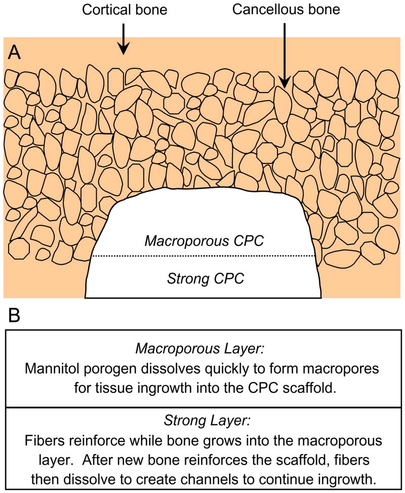
The present study explored a unique approach for providing the needed early strength via a layered CPC structure (Fig. 1A). First, a macroporous CPC paste was placed into the bone cavity. Then a strong CPC paste was placed to fill the cavity. As shown in Fig. 1B, fast-soluble porogens such as mannitol particles could be incorporated into the macroporous layer to provide immediate macropores for tissue ingrowth, while the strong layer could be fiber-reinforced to provide the early strength to the implant. Previous studies showed that significant bone ingrowth into porous implants occurred in a few weeks [27,28]. Once new bone has grown into the macroporous layer, thus increasing the strength, the absorbable fibers in the strong layer would then dissolve to create long macroporous channels for continued tissue ingrowth.
Fig. 1.
Schematic of cortical and cancellous bone, showing a cavity that was partially filled with a macroporous CPC paste, followed by a strong CPC paste. Fast-soluble mannitol could be incorporated into the macroporous CPC layer for tissue ingrowth, while the strong layer would provide the needed early strength. Once new bone has grown into the macroporous layer, thus strengthening the implant, the fibers in the strong layer would then dissolve to create macroporous channels for continued ingrowth.
The objective of this study was to develop a macroporous CPC/strong CPC-layered structure to provide the needed early strength to the macroporous CPC, and to understand relationships between mechanical properties, porosity and layer thickness ratios. Three hypotheses were tested: (1) the layered structure would have a significantly higher strength than the macroporous CPC alone without a layered structure; (2) the mechanical properties of the overall implant would depend significantly on the porosity in the macroporous layer; (3) the macroporous layer thickness/strong layer thickness ratio would be a key design parameter for the layered structure.
2. Materials and methods
2.1. CPC powder
The TTCP powder was synthesized from a solid-state reaction between equimolar amounts of CaHPO4 (DCPA) and CaCO3 (J.T. Baker Chemical, Phillipsburg, NJ), which were mixed and heated at 1500 °C for 6 h in a furnace (Model 51333, Lindberg, Watertown, WI). The heated mixture was ground in a blender and sieved to obtain TTCP particles with sizes ranging from approximately 1–80 μm, with a median particle size of approximately 17 μm. The DCPA powder had a particle size range from 0.4 to 3 μm, with a median size of about 1 μm. The TTCP and DCPA powders were mixed at mass fractions of 73% TTCP and 27% DCPA (the TTCP/DCPA mol/mol ratio was equal to 1) to form the CPC powder.
2.2. Chitosan
A chitosan liquid was made by mixing chitosan lactate (VANSON, Redmond, WA; referred to as chitosan) with distilled water at a mass fraction of 15% (i.e., chitosan/(water+chitosan) = 15% by mass), based on the results of previous studies [29,30]. Chitosan and its derivatives are natural biopolymers found in arthropod exoskeletons; they are biocompatible, biodegradable and hydrophilic. Although chitosan is not bioactive, the bioactivity can be provided by CPC in a CPC–chitosan composite. The purpose of incorporating chitosan into CPC in the present study was to strengthen the CPC.
2.3. Porogen
Water-soluble mannitol crystals were used to produce macropores in CPC. Mannitol was selected because it has the appropriate solubility, is non-toxic, and is physiologically compatible [22]. Mannitol (CH2OH[-CHOH]4CH2OH, Sigma Chemical, St. Louis, MO) was recrystallized in an ethanol/water solution at 50/50 by volume, filtered, dried, ground, and sieved through openings of 500 μm (top sieve) and 300 μm (bottom sieve) [31]. The mannitol crystals were mixed with CPC powder at the following mannitol/(mannitol+CPC powder) mass fractions, M = 0, 0.1, 0.2, 0.3, 0.4, 0.5, 0.6, and 0.7. M of 0.7 is equivalent to 70%.
2.4. Absorbable fiber
An absorbable fiber (Vicryl, Ethicon, Somerville, NJ) was selected because this fiber was clinically used as a suture material, and it possessed a relatively high strength [32]. This suture consisted of individual fibers braided into a bundle with a bundle diameter of 322 μm. It provided substantial strength and toughness for about 4 weeks, and then dissolved and produced macropores in CPC as shown in a previous study [33]. As in that study, the suture was cut to filaments of 8 mm in length and randomly mixed into the CPC paste. A fiber volume fraction of 30% (fiber volume/specimen volume) was used following a previous study, which showed that it provided substantial reinforcement without rendering the paste too dry [34].
2.5. Specimen fabrication
Four groups of specimens were fabricated. The purpose of Group 1 was to create macropores in CPC and determine the effect of chitosan reinforcement on macroporous CPC. Table 1 lists four materials for Group 1. The mannitol/(CPC powder+mannitol) mass fraction M was fixed at 0.4 (for Group 2, the mannitol mass fraction was systematically varied from 0 to 0.7). The liquid was a 0.75 mol/L sodium phosphate solution (Abbott Laboratories, North Chicago, IL) to cause cement fast setting [22]. Fast setting was needed for specimens containing mannitol. This is because in a slow-setting cement the mannitol crystals would have enough time to dissolve, coating the TTCP and DCPA particles with a film of mannitol and hindering the setting reaction of the cement. Both the chitosan solution and the sodium phosphate solution could induce fast setting. One purpose of this group was to determine their effects on setting and mechanical strength. The same powder:liquid mass ratio of 2:1 was used for Groups 1–4.
Table 1.
Group 1: macropores in CPC and effect of chitosan reinforcement
| Materials | Powder | Liquid |
|---|---|---|
| CPC without macropores | CPC powder | Water |
| CPC–sodium phosphate without macropores | CPC powder | Sodium phosphate solutiona |
| CPC–sodium phosphate with macropores | CPC powder+mannitolb | Sodium phosphate solutiona |
| CPC–chitosan with macropores | CPC powder+mannitolb | Chitosan solutionc |
This was a 0.75 mol/L sodium phosphate solution (Abbott Laboratories, North Chicago, IL) to cause fast-setting to the cement.
Mannitol was a porogen that was used to create macropores in CPC. The mannitol/(CPC powder+mannitol) mass fraction M was fixed at 0.4 for Group 1.
Chitosan biopolymer was used to cause fast-setting and strengthening to the cement. The chitosan/(chitosan+water) mass fraction = 15%.
Each powder and liquid were mixed and the paste was filled into a rectangular stainless-steel mold of 3 × 4 × 25 mm3, sandwiched between two glass slides. The specimen was allowed to set in a humidor with 100% relative humidity at 37 °C for 4 h [22]. Then, the hardened specimens were demolded and immersed in a simulated physiological solution (1.15 mmol/L Ca, 1.2 mmol/L P, 133 mmol/L NaCl, 50 mmol/L HEPES, buffered to a pH of 7.4), and stored at 37 °C for 20 h prior to mechanical testing [35]. Preliminary studies showed that this immersion dissolved the mannitol and created macropores in CPC.
Table 2 lists the compositions in Group 2 for the purpose of systematically studying the effect of mannitol content on the CPC–chitosan composite. The powder:liquid mass ratio was 2:1 for all four Groups. Specimens were fabricated as described for Group 1.
Table 2.
Group 2: effect of mannitol content on CPC–chitosan scaffold properties
| Ma | 0 | 0.1 | 0.2 | 0.3 | 0.4 | 0.5 | 0.6 | 0.7 |
|---|---|---|---|---|---|---|---|---|
| CPC cement liquid = 15% chitosan | ||||||||
M = Mannitol/(CPC Powder+Mannitol) mass fraction.
Table 3 lists Group 3 for the study of the macroporous CPC/strong CPC-layered structure as a function of pore volume fraction in the macroporous layer. Using the 3 × 4 × 25 mm3 mold, each layer had a width of approximately 4 mm, a length of 25 mm, and a thickness of 1.5 mm. The fiber layer used CPC powder with 30% by volume of fibers (= fiber volume/[3 × 4 × 1.5 mm3]). The fiber volume was calculated by fiber density and fiber mass.
Table 3.
Group 3: effect of porosity in macroporous layer on macroporous/strong CPC layered structure properties
| Powder | Liquid | Fiber volume fraction (%) | |
|---|---|---|---|
| Strong layer | CPC powder | 15% chitosan | 30 |
| Macroporous layer | CPC+mannitol (at M = 0, 0.1, 0.2, 0.3, 0.4, 0.5, 0.6, 0.7)a | 15% chitosan | 0 |
M = Mannitol/(CPC+Mannitol) mass fraction.
Table 4 lists Group 4 for the investigation of the effect of layer thickness ratio. The macroporous layer used the CPC powder with mannitol at an intermediate mannitol mass fraction of 0.4 (without fibers). The strong layer contained CPC powder and 30% by volume of fibers (without mannitol). For both layers, the 15% chitosan liquid was used for reinforcement. Specimens were fabricated and immersed in a physiological solution as described for Group 1.
Table 4.
Group 4: effect of strong layer/macroporous layer thickness ratio
| Strong layer, a (mm) | 0 | 0.5 | 1.0 | 1.5 | 2.0 | 2.5 | 3.0 |
| Macroporous layer, b (mm) | 3.0 | 2.5 | 2.0 | 1.5 | 1.0 | 0.5 | 0 |
| a/h ratioa | 0 | 0.17 | 0.33 | 0.50 | 0.67 | 0.83 | 1 |
h = a+b, as shown at top of Fig. 7. Other parameters for Table 4 are stated in the text.
2.6. Cement setting time
The powder and liquid of each material were manually mixed with a spatula to form a cohesive paste that was filled into a stainless steel mold of 6mm diameter and 3 mm deep. Each specimen in the mold was placed in a humidor with 100% relative humidity at 37 °C. When the powder component of the specimen did not come off when scrubbed gently with fingers as described in a previous study [35], the setting reaction had occurred enough to hold the specimen together. The time measured from the powder–liquid mixing to this point was used as the setting time for the specimen.
2.7. Mechanical testing
Flexural strength and elastic modulus were measured in three-point flexure with a 20 mm span at a crosshead-speed of 1 mm/min on a computer-controlled Universal Testing Machine (5500R, MTS, Cary, NC). Flexural strength was calculated by S = 3FmaxL/(2bh2), where Fmax is the maximum load on the load–displacement curve, L is flexure span, b is specimen width, and h is specimen thickness. Elastic modulus was calculated by E = (F/c) (L3/[4bh3]), where load F divided by the corresponding displacement c is the slope of the load–displacement curve in the linear elastic region [36].
2.8. Density, porosity, and macropore size distribution
The fractured halves of specimens of Group 2 for which the mannitol had been leached out were used to measure the density and porosity. The ends of each specimen were polished with 600 SiC paper to render them flat and approximately parallel [22]. The specimens were dried in a vacuum oven (Model DP-21, American Scientific Products, McGaw Park, IL) at 60 °C for 24 h. As described in a previous study [22], the density, d, of the material was measured by using the specimen mass divided by the specimen volume. The volume was calculated from the specimen dimensions, measured with a micrometer; each dimension was the average of three locations along the specimen. A previous study showed that this method yielded porosity and density that closely matched those measured by a mercury intrusion method [22].
For CPC specimens without chitosan, the porosity of the specimen, P, can be obtained by
| (1) |
where dHA is the density of fully dense hydroxyapatite without chitosan and is equal to 3.14 g/cm3 [22], and d is the measured density of the specimen. For CPC–chitosan composite, the porosity can be similarly calculated by P = (dHA+CN−d)/dHA+CN, where dHA+CN is the density of the fully dense hydroxyapatite–chitosan composite [31]. P can be calculated using the measured density d of the specimen, the density of chitosan lactate (0.55 g/cm3, manufacturer’s data), together with the masses of the components used to make the specimen [31].
The macropore size distribution was measured via a scanning electron microscope (SEM, model JSM-5300, JEOL, Peabody, MA). Specimen sections were sputter-coated with gold and examined in the SEM to measure the macropore length and diameter because the pores were elongated. CPC also contained numerous micropores of sizes ranging from tens of nm to a few μm. Since the purpose of the present study was to create macropores in CPC for cell infiltration and tissue ingrowth, only macropores of sizes of about 50μm or larger were included in the analysis of macropore size distribution.
2.9. Conversion to hydroxyapatite
Powder X-ray diffraction (XRD) analysis was used to examine the effect of chitosan and mannitol on the CPC conversion to hydroxyapatite for specimens of Group 1 [29]. Specimens were dried and milled into powder by mortar and pestle. The XRD patterns were recorded with a powder X-ray diffractometer (Rigaku, Danvers, MA) using graphite-monochromatized copper Kα radiation (λ = 0.154 nm) generated at 40 kV and 40 mA. The 0 02 peak intensity of hydroxyapatite was used to measure the percentage of conversion to hydroxyapatite. All data were collected in a continuous scan mode (1° 2θmin−1, step time 0.6 s, step size 0.01°).
2.10. SEM and statistics
Selected specimen surfaces and cross-sections were examined via the same SEM. One-way and two-way ANOVA were performed to detect significant effects. Tukey’s multiple comparison was used to compare the data at a family confidence coefficient of 0.95.
3. Results
3.1. Group 1: effect of porosity and chitosan reinforcement
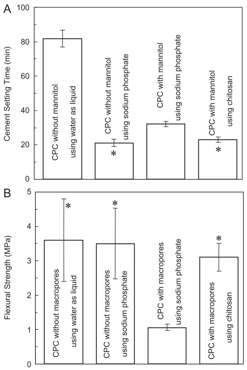
Fig. 2A plots the cement setting time for Group 1. CPC with water had a relatively slow setting; the use of a sodium phosphate solution reduced the setting time (mean±sd; n = 5) to (21.0±2.5) min. The incorporation of mannitol significantly increased the setting time to (32.0±1.4) min (p<0.05). However, the use of chitosan, even with the presence of mannitol, yielded a fast setting time of (23.4±1.3) min, which is not significantly different from the (21.0±2.5) min without mannitol (p>0.1).
Fig. 2.
Effects of porosity and chitosan reinforcement on (A) setting time and (B) flexural strength, for Group 1. Setting time for CPC using water without macropores was measured in a previous study [37]. In each plot, “*” indicates values that are not significantly different from each other (Tukey’s multiple comparison test at 0.05).
As shown in Fig. 2B, CPC without macropores had a flexural strength (mean±sd; n = 6) of (3.6±1.2) MPa using water, not significantly different from the (3.5±1.1) MPa using the sodium phosphate solution (p>0.1). Hence fast setting (A) was achieved without compromising strength. However, when macropores were created in CPC using mannitol, the strength decreased precipitously to (1.1±0.1) MPa (p<0.05). With chitosan reinforcement, the strength was increased back to (3.1±0.4) MPa even with macropores (Fig. 2B). The strength of the macroporous CPC–chitosan scaffold matched that of CPC without macropores (p>0.10).
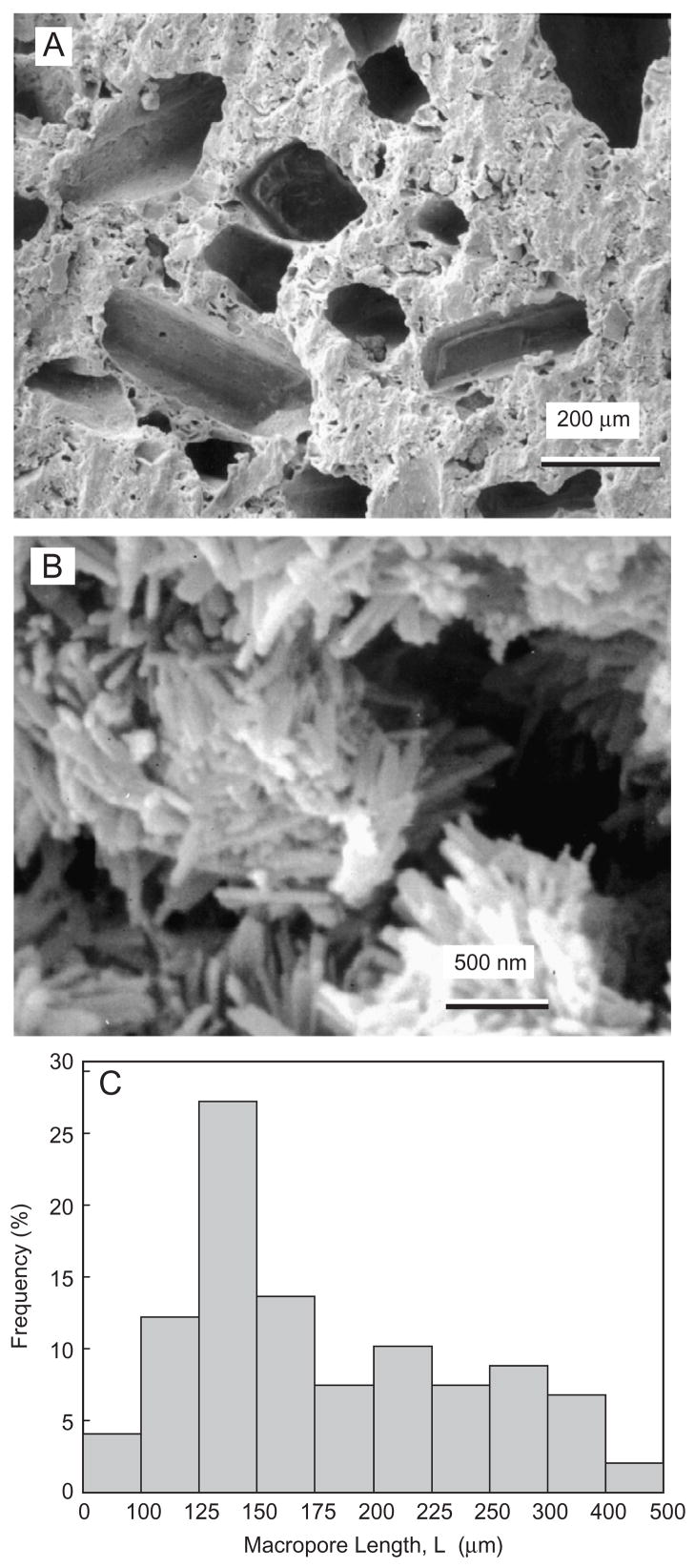
Fig. 3A shows typical macropores produced by mannitol in the CPC–chitosan composite. The macropores appeared to be well formed in the shapes of the entrapped mannitol crystals, with no noticeable difference between specimens with or without chitosan. The apatite crystals that make up the CPC are shown in Fig. 3B for CPC without chitosan. Similar nano-sized crystals were observed in the CPC with chitosan. Fig. 3C plots the histogram of macropore size distribution by measuring 147 randomly selected macropores in the cement specimens. The macropore length (mean±sd; n = 147) was (183±73) μm. The macropore diameter was (95±40) μm. Hence the pore aspect ratio was 1.9.
Fig. 3.
(A) Macropores produced by mannitol dissolution in CPC–chitosan composite. (B) Nano apatite crystals in macroporous CPC without chitosan. Nano crystals were also observed in CPC with chitosan. (C) Histogram of macropore size distribution by measuring 147 randomly selected macropores in CPC. The macropore length (mean±sd; n = 147) was (183±73) μm. The macropore diameter was (95±40) μm. The pore aspect ratio was 1.9.
The mass percentage of CPC conversion to hydroxyapatite (mean±sd; n = 3) ranged from (91.6±3.7)% for CPC using water without macropores to (95.1±3.2)% for CPC–chitosan with macropores, with no significant difference between the materials (p>0.1).
3.2. Group 2: effect of mannitol content on mechanical properties
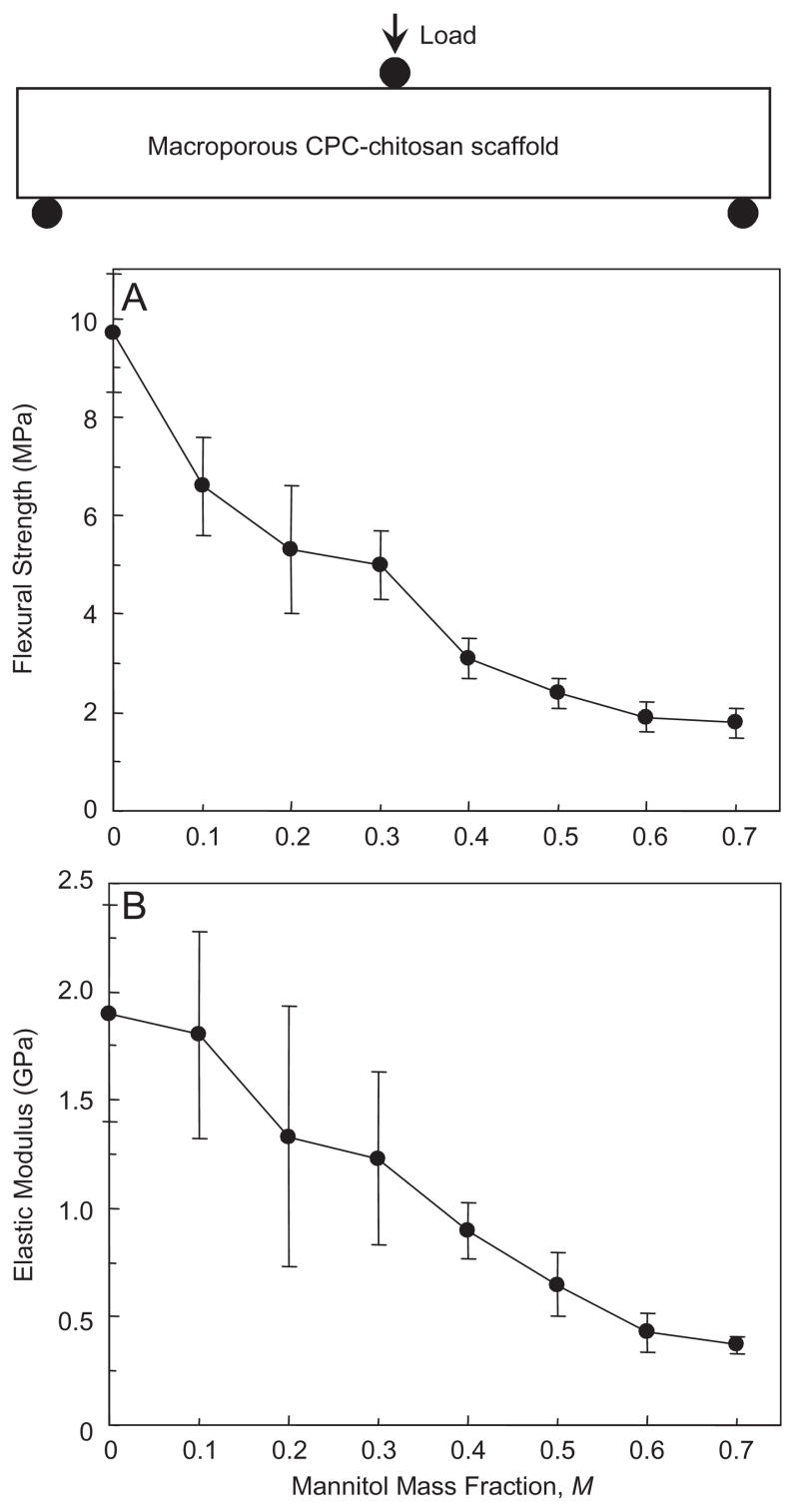
Flexural strength and elastic modulus for the CPC–chitosan scaffold are plotted as a function of mannitol mass fraction (Fig. 4). Flexural strength significantly decreased from (9.7±1.2) MPa with no mannitol to (3.1±0.4) MPa with mannitol mass fraction of 0.4, and further to (1.8±0.3) MPa with mannitol mass fraction of 0.7 (p<0.05). The corresponding elastic modulus significantly (p<0.05) decreased from (1.85±0.46) GPa to (0.88± 0.13) GPa, and to (0.37±0.04) GPa, at these three mannitol fractions, respectively.
Fig. 4.
Effect of mannitol content on mechanical properties of CPC–chitosan composite scaffold. (A) Flexural strength, and (B) elastic modulus. A mannitol mass fraction of 70% is equivalent to 0.70. Each value is mean±sd; n = 6, with the error bar showing one standard deviation (sd). Line connects data for visual clarity.
3.3. Group 2: effect of mannitol content on density and porosity
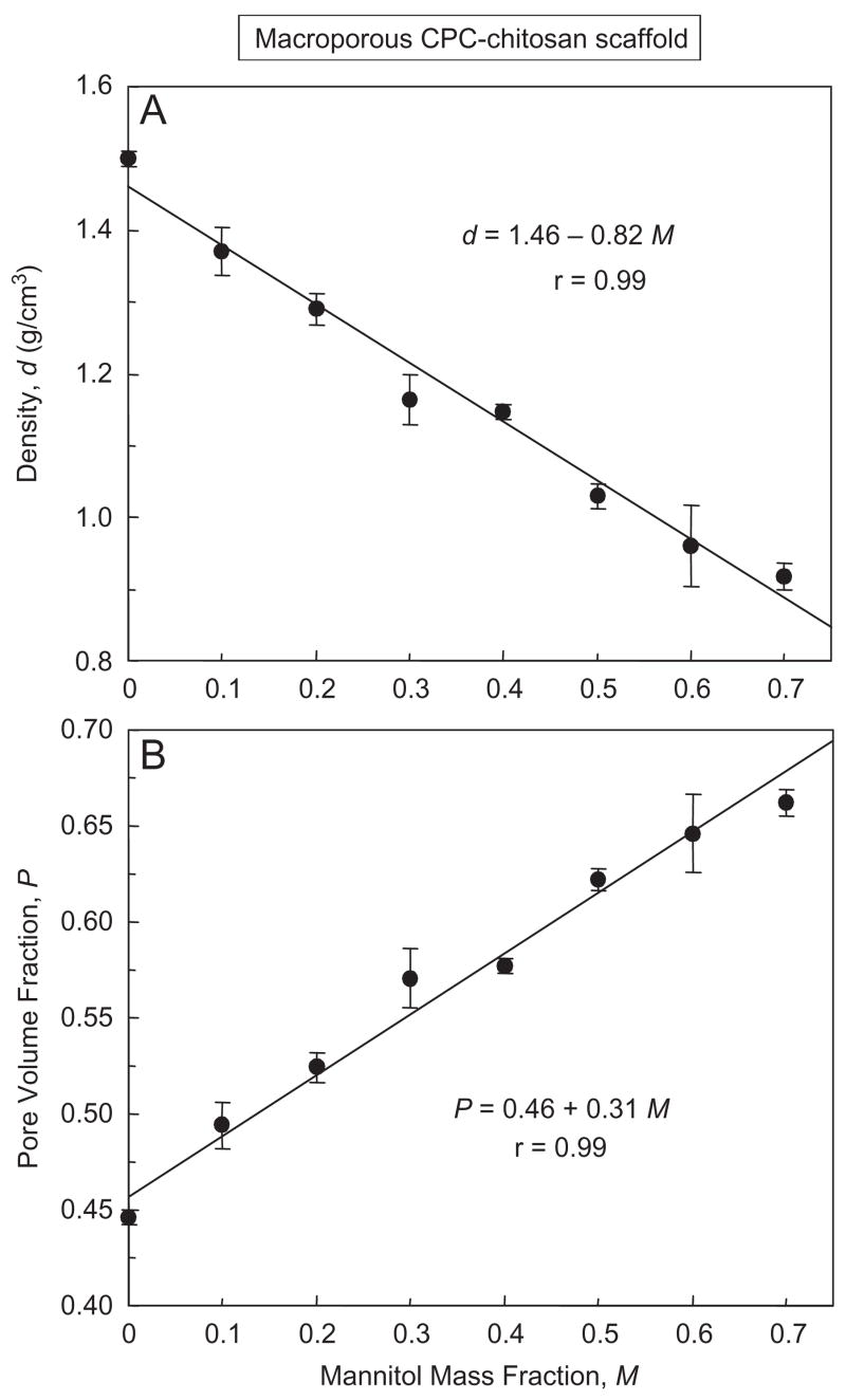
The density of CPC–chitosan–mannitol scaffold after mannitol dissolution is plotted in Fig. 5A. The density (mean±sd; n = 6) decreased from (1.50±0.01) g/cm3 with no mannitol, to (1.15±0.01) g/cm3 with mannitol mass fraction of 0.4, and further to (0.92±0.02) g/cm3 with mannitol mass fraction of 0.7 (p<0.05). The corresponding porosity (pore volume fraction) in (B) increased from (44.6±0.4)% to (57.7±0.4)%, and further to (66.2±0.7)%, respectively (p<0.05). A pore volume fraction of 66.2% and 0.662 are used interchangeably. The lines are linear best fits to the data, with correlation coefficient r = 0.99 for both density and porosity.
Fig. 5.
Effect of mannitol content on (A) density, and (B) porosity, of CPC–chitosan composite scaffold. Each value is mean±sd; n = 6, with the error bar showing one standard deviation. For the y-axis of (B), a pore volume fraction P of 65% is equivalent to 0.65. For the x-axis, a mannitol mass fraction of 70% is equivalent to 0.70. Lines are linear best fits to the data with correlation coefficient r = 0.99.
3.4. Group 3: effect of porosity in the macroporous layer on the overall layered structure
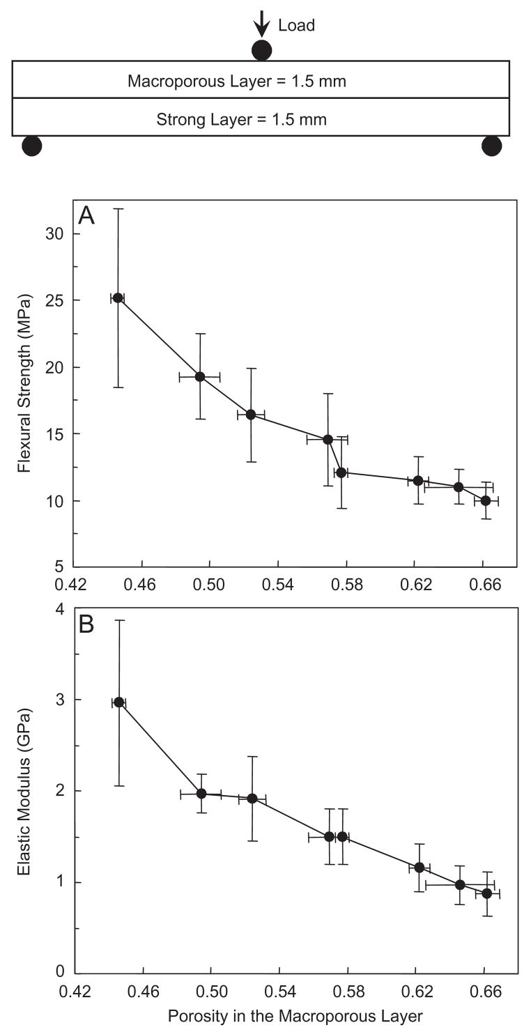
As shown in the schematic at the top of Fig. 6, the layer thickness was fixed, but the porosity inside the macroporous layer was changed by varying the mannitol fraction from 0 to 0.7. The strong layer contained fibers but no mannitol and was not varied. The flexural strength of the overall structure (Fig. 6A) decreased from (25.2±6.7) MPa at a porosity inside the macroporous layer of 0.446, to (16.4±3.5) MPa at a porosity of 0.524, and to (10.0±1.4) MPa at a porosity of 0.662 (p<0.05). Elastic modulus (Fig. 6B) showed a similar, decreasing trend.
Fig. 6.
Effect of porosity in the macroporous layer on the layered CPC structure: (A) flexural strength, and (B) elastic modulus. The layer thickness was fixed at 1.5 mm each. The porosity inside the macroporous layer was changed by varying the mannitol mass fraction in that layer from 0 to 0.7. The strong layer contained 30% fibers but no mannitol. The macroporous layer had no fiber. Both layers used the liquid with 15% chitosan. Each value is mean±sd; n = 6. Line connects data for visual clarity.
Compared to the macroporous CPC–chitosan composite in Fig. 4 without a strong layer, the strengths of the layered structure in Fig. 6A are substantially higher. At mannitol mass fraction of 0.2, the strength of the layered structure in Fig. 6 was (16.4±3.5) MPa, three times higher than the (5.3±1.3) MPa of macroporous CPC–chitosan without a strong layer in Fig. 4. At mannitol fraction of 0.7, the strength of the layered structure was (10.0±1.4) MPa, 5-fold greater than the (1.8±0.3) MPa of the macroporous CPC–chitosan without a strong layer.
3.5. Group 4: effect of layer thickness ratio on the layered-structure properties
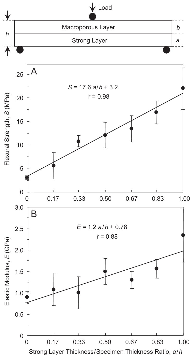
In Fig. 7, a/h = 0, 0.17, 0.33, 0.50, 0.67, 0.83, and 1 (Table 4). The flexural strength S as a function of a/h is plotted in Fig. 7A, and the corresponding elastic modulus E is plotted in (B). Both S and E are significantly increased with increasing a/h (Tukey’s at 0.05). The equations in Fig. 7 are described Section 4.
Fig. 7.
Effect of CPC layer thickness ratio. The strong layer/specimen thickness ratios, a/h, were: 0, 0.17, 0.33, 0.50, 0.67, 0.83, and 1.00. The macroporous layer used a mannitol mass fraction of 0.4 (without fibers). The strong layer used 30% by volume of fibers (without mannitol). Both layers used the liquid with 15% chitosan. The equations and solid lines are linear best fits to the data. Each value is mean±sd; n = 6.
4. Discussion
In previous studies, several different compositions of CPC were developed [8–15]. A number of other studies investigated the setting reaction [8], in vitro aging [12], macroporous scaffolds [22–26,32–35], and shelf life of CPC [38]. Fast-setting and anti-washout CPC were also formulated [9,35,39]. Recent studies examined the injectability of various CPC [13,40–42].
4.1. Functionally graded
Based on our literature search, the present study appeared to represent the first effort in using an in situ-hardening CPC to design a layered, strong and macroporous, “functionally graded” implant. A functionally graded material differs from a uniform composite in that it has varying composition and property from one side of the material to the other side, either continuously, or stepwise as in a layered structure [43,44]. Our simple bi-layer structure consisted of a first layer serving the function of macropores for cell infiltration and for rapid integration of the implant with the surrounding bone. The second layer served the function of providing the needed early strength to the CPC implant. After significant bone ingrowth into the macroporous layer, thus strengthening the implant, the fibers in the strong layer would then dissolve to create additional macropores to continue the tissue ingrowth. Mechanical strength and macroporosity are conflicting requirements. However, the novel functionally graded CPC enabled a relatively high strength and macroporosity to be simultaneously achieved.
Further studies are needed to investigate more complicated, functionally graded CPC. For example, a tri-layer implant could have a macroporous first layer, a second layer with fibers of a medium dissolution rate, and a strong external layer with fibers having a slow dissolution rate to provide longer-term reinforcement. Another example would be to use a fast-resorbable CPC as the first layer, followed by a slowly resorbable, but much stronger composition, to better match the new bone formation rate. While further studies are needed to develop these functionally graded CPCs, the present study provided information on the creation of macropores, the effect of chitosan reinforcement, and the influence of layer thickness ratio, on the layered implant properties. Such information may be useful not only to direct-filling restorations, but also to the design of pre-formed implants.
4.2. Effect of strong layer reinforcement
Our first hypothesis was that the layered structure would have a significantly higher strength than the macroporous CPC alone without a layered structure. The strengths in Fig. 4 for the macroporous CPC alone and the much higher strengths in Fig. 6 for the layered structure proved this hypothesis. Macropores severely degraded the CPC strength (Fig. 2B), but chitosan reinforcement effectively increased the strength. However, even with chitosan reinforcement, increasing the mannitol content significantly decreased the scaffold strength (Fig. 4A). At mannitol mass fractions of 0.4–0.7, with corresponding porosity of 57.7–66.2%, the scaffold strength was only 2–3 MPa. Fortunately, with a strong layer reinforcement, the flexural strength was dramatically increased to >10 MPa, even with a porosity of around 60% (Fig. 6A). In comparison, sintered porous hydroxyapatite implants have flexural strengths ranging from 2 to 11 MPa [45]. Cancellous bone has a tensile strength of about 3.5 MPa [46].
While the measurements are not identical and direct comparison cannot be made, these data suggest that the strength of the CPC layered structure matched/exceeded those of sintered porous hydroxyapatite implants and cancellous bone, even with a highly porous CPC layer with macropores suitable for cell infiltration and tissue ingrowth. While matching/exceeding the strength of sintered hydroxyapatite implants, the layered CPC structure is advantageous because of its in situ hardening ability without machining, intimate adaptation to neighboring bone, and ability to be replaced by new bone.
4.3. Effect of porosity
Our second hypothesis was that the mechanical properties of the overall implant would depend significantly on the porosity in the macroporous layer. This hypothesis was proven in Fig. 6. When the porosity in the macroporous layer increased, the strength of the overall implant steadily decreased from about 25 to 10 MPa. The elastic modulus decreased from about 3 to 1 GPa.
It would be useful to predict the porosity based on mannitol mass fraction. The density d of the CPC–chitosan scaffold was related to the mannitol mass fraction M by d = 1.46–0.82 M. The porosity P was related to M by P = 0.46+0.31 M. Hence P could be predicted once M is known, and M could be tailored to obtain a specific P for a particular application.
It is interesting to compare the porosity values with previous studies. Previous studies on sintered hydroxyapatite implants reported pore volume fractions ranging from 34% to 48% [47], 40% [6], 48% and as high as 75% [48]. In the present study, the macroporous CPC–chitosan–mannitol layer, after mannitol dissolution, had pore volume fractions of 44.6–66.2%. They are within the range of those in previous studies. In addition, the strong layer contained 30% by volume of absorbable fibers. These fibers could provide the needed early strength for several weeks, then dissolve and create macropores as shown in previous studies [31–33]. Hence, in addition to the macropores in the macroporous layer, the strong layer could also create about 30% of macropores after fiber dissolution.
It is also interesting to compare pore sizes with previous studies. Previous studies showed that pore sizes of at least 100 μm were required for significant bone ingrowth [47]. Previous studies used hydroxyapatite implants with pore diameters of 100 and 150 [6,48], and 500 μm [19]. In the present study, the macropore sizes in Figs. 3A and C were similar to those of previous values and suitable for cell infiltration and tissue ingrowth. Furthermore, the dissolution of fibers in the strong layer would create cylindrical macropore channels about the diameter of the fibers (322 μm) as shown in previous studies [34,35].
4.4. Effect of layer thickness ratio
Our third hypothesis was that the macroporous layer thickness/strong layer thickness ratio would be a key design parameter for the layered structure. In Fig. 7, a is defined as the strong layer thickness, and h is the overall specimen thickness. The following empirical relationship is proposed:
| (2) |
where S is the flexural strength of the overall specimen, Sstrong layer is the strength of the strong layer, and Smacroporous layer is the strength of the macroporous layer. This equation agrees with the expectation that, in the extreme case when a = 0 and a/h = 0, there is only a single macroporous layer with no strong layer, hence S = Smacroporous layer. In the other extreme case, when a = h, there is only a strong layer without a macroporous layer, hence S = Sstrong layer.
Similarly, elastic modulus
| (3) |
Linear regression best fits of these equations to the experimental data in Fig. 6 yielded:
| (4) |
| (5) |
with correlation coefficient r = 0.98 and 0.88, respectively.
The first implication of these equations is that, the thickness ratio a/h could be tailored to achieve a predetermined strength based on specific application needs. A larger a value would yield a larger S value. A smaller a would yield a thicker macroporous layer with the potential benefit of more new bone formation and faster implant resorption. The second implication is that S in Eq. (2) increases with increasing Sstrong layer and Smacroporous layer; hence both the strong layer and the macroporous layer need to be reinforced to obtain the maximum S. The third point is that the coefficients in Eqs. (2) and (3) (e.g., Sstrong layer, and Smacroporous layer) depend on the properties of the individual layers. Hence while the general Eqs. (2) and (3) may be valid for different cement systems, Eqs. (4) and (5) are cement-specific and dependent on the different CPC compositions and powder to liquid ratios.
When natural bone is subjected to bending in different directions, there is always a cortical bone layer supporting the maximum tensile stress. That was why in our test configuration, the strong fiber layer was placed in tension. However, in cases where the bone was subjected in uniaxial tension, then the macroporous layer would also be in tension. Further studies are needed to: (1) examine the implant properties with the macroporous layer in tension; (2) design other functionally graded CPC structures with tailored resorption rates and load-bearing capabilities; and (3) investigate the layered structures in animal models to examine the effects of the macroporous layer on new bone formation.
5. Conclusions
An in situ hardening, strong and macroporous, nano-apatite implant was designed. The macroporous layer had macropores suitable for tissue ingrowth. The strong layer provided the needed early strength. The rationale was that after bone ingrowth into the macroporous layer, thus strengthening the implant, the fibers in the strong layer would then dissolve to create additional macropores for continued ingrowth. While mechanical strength and macroporosity are usually conflicting requirements, the novel functionally graded CPC enabled a relatively high strength and macroporosity to be achieved simultaneously. Relationships were obtained between flexural strength, modulus and implant layer thickness ratios. These relationships may be useful in tailoring the thickness ratios and designing each layer with desired properties, based on the specific needs for the stress-bearing ability and for the amount of macroporosity.
Acknowledgments
We thank Drs. S. Takagi and L.C. Chow for discussions. This study was supported by USPHS Grants DE14190, NIST, and the ADAF.
Footnotes
Disclaimer
Certain commercial materials and equipment are identified in this paper to specify experimental procedures. This does not imply recommendation by NIST or ADAF or that the material identified is necessarily the best for the purpose. Unless otherwise specified, one standard deviation was used as the estimated standard uncertainty of the measurements.
References
- 1.Hench LL. Bioceramics. J Am Ceram Soc. 1998;81:1705–28. [Google Scholar]
- 2.Laurencin CT, Ambrosio AMA, Borden MD, Cooper JA. Tissue engineering: orthopedic applications. Ann Rev Biomed Eng. 1999;1:19–46. doi: 10.1146/annurev.bioeng.1.1.19. [DOI] [PubMed] [Google Scholar]
- 3.LeGeros RZ, LeGeros JP. Dense hydroxyapatite. In: Hench LL, Wilson J, editors. An introduction to bioceramics. New Jersey: World Scientific; 1993. pp. 139–80. [Google Scholar]
- 4.Thomson RC, Yaszemski MJ, Powers JM, Mikos AG. Hydroxyapatite fiber reinforced poly(α-hydroxy ester) foams for bone regeneration. Biomaterials. 1998;19:1935–43. doi: 10.1016/s0142-9612(98)00097-0. [DOI] [PubMed] [Google Scholar]
- 5.Ducheyne P, Qiu Q. Bioactive ceramics: the effect of surface reactivity on bone formation and bone cell function. Biomaterials. 1999;20:2287–303. doi: 10.1016/s0142-9612(99)00181-7. [DOI] [PubMed] [Google Scholar]
- 6.Pilliar RM, Filiaggi MJ, Wells JD, Grynpas MD, Kandel RA. Porous calcium polyphosphate scaffolds for bone substitute applications—in vitro characterization. Biomaterials. 2001;22:963–72. doi: 10.1016/s0142-9612(00)00261-1. [DOI] [PubMed] [Google Scholar]
- 7.Brown WE, Chow LC. A new calcium phosphate water setting cement. In: Brown PW, editor. Cements research progress. Westerville, OH: American Ceramic Society; 1986. pp. 352–79. [Google Scholar]
- 8.Ginebra MP, Fernandez E, De Maeyer EAP, Verbeeck RMH, Boltong MG, Ginebra J, et al. Setting reaction and hardening of an apatite calcium phosphate cement. J Dent Res. 1997;76:905–12. doi: 10.1177/00220345970760041201. [DOI] [PubMed] [Google Scholar]
- 9.Ishikawa K, Miyamoto Y, Takechi M, Toh T, Kon M, Nagayama M, et al. Non-decay type fast-setting calcium phosphate cement: hydroxyapatite putty containing an increased amount of sodium alginate. J Biomed Mater Res. 1997;36A:393–9. doi: 10.1002/(sici)1097-4636(19970905)36:3<393::aid-jbm14>3.0.co;2-f. [DOI] [PubMed] [Google Scholar]
- 10.Durucan C, Brown PW. Low temperature formation of calcium-deficient hydroxyapatite-PLA/PLGA composites. J Biomed Mater Res. 2000;51A:717–25. doi: 10.1002/1097-4636(20000915)51:4<717::aid-jbm21>3.0.co;2-q. [DOI] [PubMed] [Google Scholar]
- 11.Yokoyama A, Yamamoto S, Kawasaki T, Kohgo T, Nakasu M. Development of calcium phosphate cement using chitosan and citric acid for bone substitute materials. Biomaterials. 2002;23:1091–101. doi: 10.1016/s0142-9612(01)00221-6. [DOI] [PubMed] [Google Scholar]
- 12.Grover LM, Knowles JC, Fleming GJP, Barralet JE. In vitro ageing of brushite calcium phosphate cement. Biomaterials. 2003;24:4133–41. doi: 10.1016/s0142-9612(03)00293-x. [DOI] [PubMed] [Google Scholar]
- 13.Bohner M, Baroud G. Injectability of calcium phosphate pastes. Biomaterials. 2005;26:1553–63. doi: 10.1016/j.biomaterials.2004.05.010. [DOI] [PubMed] [Google Scholar]
- 14.Fernández E, Sarda S, Hcu M, Vlad MD, Gel M, Valls S, et al. High-strength apatitic cement by modification with superplasticizers. Biomaterials. 2005;26:2289–96. doi: 10.1016/j.biomaterials.2004.07.043. [DOI] [PubMed] [Google Scholar]
- 15.Julien M, Khairoun I, LeGeros RZ, Delplace S, Pilet P, Weiss P, et al. Physico-chemical-mechanical and in vitro biological properties of calcium phosphate cements with doped amorphous calcium phosphates. Biomaterials. 2007;28:956–65. doi: 10.1016/j.biomaterials.2006.10.018. [DOI] [PubMed] [Google Scholar]
- 16.Costantino PD, Friedman CD, Jones K, Chow LC, Sisson GA. Experimental hydroxyapatite cement cranioplasty. Plast Reconstr Surg. 1992;90:174–91. [PubMed] [Google Scholar]
- 17.Friedman CD, Costantino PD, Takagi S, Chow LC. BoneSourceTM hydroxyapatite cement: a novel biomaterial for craniofacial skeletal tissue engineering and reconstruction. J Biomed Mater Res (Appl Biomater) 1998;43B:428–32. doi: 10.1002/(sici)1097-4636(199824)43:4<428::aid-jbm10>3.0.co;2-0. [DOI] [PubMed] [Google Scholar]
- 18.Chow LC. Calcium phosphate cements: chemistry, properties, and applications. Mater Res Symp Proc. 2000;599:27–37. [Google Scholar]
- 19.Hing KA, Best SM, Bonfield W. Characterization of porous hydroxyapatite. J Mater Sci: Mater Med. 1999;10:135–45. doi: 10.1023/a:1008929305897. [DOI] [PubMed] [Google Scholar]
- 20.Livingston T, Ducheyne P, Garino J. In vivo evaluation of a bioactive scaffold for bone tissue engineering. J Biomed Mater Res. 2002;62A:1–13. doi: 10.1002/jbm.10157. [DOI] [PubMed] [Google Scholar]
- 21.Gan L, Pilliar RM. Calcium phosphate sol–gel-derived thin films on porous-surfaced implants for enhanced osteoconductivity. Part I: synthesis and characterization. Biomaterials. 2004;25:5303–12. doi: 10.1016/j.biomaterials.2003.12.038. [DOI] [PubMed] [Google Scholar]
- 22.Xu HHK, Quinn JB, Takagi S, Chow LC, Eichmiller FC. Strong and macroporous calcium phosphate cement: effects of porosity and fiber reinforcement. J Biomed Mater Res. 2001;57A:457–66. doi: 10.1002/1097-4636(20011205)57:3<457::aid-jbm1189>3.0.co;2-x. [DOI] [PubMed] [Google Scholar]
- 23.Almirall A, Larrecq G, Delgado JA, Martánez S, Planell JA, Ginebra MP. Fabrication of low temperature macroporous hydroxyapatite scaffolds by foaming and hydrolysis of an α-TCP paste. Biomaterials. 2004;25:3671–80. doi: 10.1016/j.biomaterials.2003.10.066. [DOI] [PubMed] [Google Scholar]
- 24.Bohner M. Calcium phosphate emulsions: possible applications. Key Eng Mater. 2001;192–195:765–8. [Google Scholar]
- 25.Fernández E, Vlad MD, Gel MM, López J, Torres R, Cauich JV, et al. Modulation of porosity in apatitic cements by the use of α-tricalcium phosphate—calcium sulphate dehydrate mixtures. Biomaterials. 2005;26:3395–404. doi: 10.1016/j.biomaterials.2004.09.023. [DOI] [PubMed] [Google Scholar]
- 26.Link DP, van den Dolder J, Jurgens WJFM, Wolke JGC, Jansen JA. Mechanical evaluation of implanted calcium phosphate cement incorporated with PLGA microparticles. Biomaterials. 2006;27:4941–7. doi: 10.1016/j.biomaterials.2006.05.022. [DOI] [PubMed] [Google Scholar]
- 27.Martin RB, Chapman MW, Holmes RE, Sartoris DJ, Shors EC, Gordon JE, et al. Effects of bone ingrowth on the strength and non-invasive assessment of a coralline hydroxyapatite material. Biomaterials. 1989;10:481–8. doi: 10.1016/0142-9612(89)90090-2. [DOI] [PubMed] [Google Scholar]
- 28.Shors EC, Holmes RE. Porous hydroxyapatite. In: Hench LL, Wilson J, editors. An introduction to bioceramics. New Jersey: World Scientific; 1993. pp. 181–98. [Google Scholar]
- 29.Xu HHK, Quinn JB, Takagi S, Chow LC. Processing and properties of strong and non-rigid calcium phosphate cement. J Dent Res. 2002;81:219–24. [PubMed] [Google Scholar]
- 30.Xu HHK, Simon CG., Jr Fast setting calcium phosphate–chitosan scaffold: mechanical properties and biocompatibility. Biomaterials. 2005;26:1337–48. doi: 10.1016/j.biomaterials.2004.04.043. [DOI] [PubMed] [Google Scholar]
- 31.Zhang Y, Xu HHK, Takagi S, Chow LC. In-situ hardening hydroxyapatite-based scaffold for bone repair. J Mater Sci: Mater Med. 2006;17:437–45. doi: 10.1007/s10856-006-8471-z. [DOI] [PubMed] [Google Scholar]
- 32.Zhang Y, Xu HHK. Effects of synergistic reinforcement and absorbable fiber strength on hydroxyapatite bone cement. J Biomed Mater Res. 2005;75A:832–40. doi: 10.1002/jbm.a.30461. [DOI] [PubMed] [Google Scholar]
- 33.Xu HHK, Quinn JB. Calcium phosphate cement containing resorbable fibers for short-term reinforcement and macroporosity. Biomaterials. 2002;23:193–202. doi: 10.1016/s0142-9612(01)00095-3. [DOI] [PubMed] [Google Scholar]
- 34.Xu HHK, Simon CG. Self-hardening calcium phosphate composite scaffold for bone tissue engineering. J Orthop Res. 2004;22:535–43. doi: 10.1016/j.orthres.2003.09.010. [DOI] [PubMed] [Google Scholar]
- 35.Xu HHK, Takagi S, Quinn JB, Chow LC. Fast-setting and anti-washout calcium phosphate scaffolds with high strength and controlled macropore formation rates. J Biomed Mater Res. 2004;68A:725–34. doi: 10.1002/jbm.a.20093. [DOI] [PubMed] [Google Scholar]
- 36.ASTM D 790–03. Standard test methods for flexural properties of unreinforced and reinforced plastic and electrical insulating materials. West Conshohocken, PA: ASTM International; 2004. [Google Scholar]
- 37.Burguera EF, Xu HHK, Weir MD. Injectable and rapid-setting calcium phosphate bone cement with dicalcium phosphate dihydrate. J Biomed Mater Res. 2006;77B:126–34. doi: 10.1002/jbm.b.30403. [DOI] [PubMed] [Google Scholar]
- 38.Gbureck U, Dembski S, Thull R, Barralet JE. Factors influencing calcium phosphate cement shelf-life. Biomaterials. 2005;26:3691–7. doi: 10.1016/j.biomaterials.2004.09.036. [DOI] [PubMed] [Google Scholar]
- 39.Ueyama Y, Ishikawa K, Mano T, Koyama T, Nagatsuka H, Matsumura T, et al. Initial tissue response to anti-washout apatite cement in the rat palatal region: comparison with conventional apatite cement. J Biomed Mater Res. 2001;55A:652–60. doi: 10.1002/1097-4636(20010615)55:4<652::aid-jbm1060>3.0.co;2-k. [DOI] [PubMed] [Google Scholar]
- 40.Gbureck U, Barralet JE, Spatz K, Grover LM, Thull R. Ionic modification of calcium phosphate cement viscosity: Part I: hypodermic injection and strength improvement of apatite cement. Biomaterials. 2004;25:2187–95. doi: 10.1016/j.biomaterials.2003.08.066. [DOI] [PubMed] [Google Scholar]
- 41.Bohner M, Gbureck U, Barralet JE. Technological issues for the development of more efficient calcium phosphate bone cements: a critical assessment. Biomaterials. 2005;26:6423–9. doi: 10.1016/j.biomaterials.2005.03.049. [DOI] [PubMed] [Google Scholar]
- 42.Xu HHK, Weir MD, Burguera EF, Fraser AM. Injectable and macroporous calcium phosphate cement scaffold. Biomaterials. 2006;27:4279–87. doi: 10.1016/j.biomaterials.2006.03.001. [DOI] [PubMed] [Google Scholar]
- 43.Rabin BH, Shiota I. Functionally gradient materials. Mater Res Soc Bull. 1995;20:14–8. [Google Scholar]
- 44.Guo H, Khor KA, Boey YC, Miao X. Laminated and functionally graded hydroxyapatite/yttria stabilized tetragonal zirconia composites fabricated by spark plasma sintering. Biomaterials. 2003;24:667–75. doi: 10.1016/s0142-9612(02)00381-2. [DOI] [PubMed] [Google Scholar]
- 45.Suchanek W, Yoshimura M. Processing and properties of hydroxyapatite-based biomaterials for use as hard tissue replacement implants. J Mater Res. 1998;13:94–117. [Google Scholar]
- 46.Damien CJ, Parsons JR. Bone graft and bone graft substitutes: a review of current technology and applications. J Appl Biomater. 1991;2:187–208. doi: 10.1002/jab.770020307. [DOI] [PubMed] [Google Scholar]
- 47.Simske SJ, Ayers RA, Bateman TA. Porous materials for bone engineering. Mater Sci Forum. 1997;250:151–82. [Google Scholar]
- 48.Tamai N, Myoui A, Tomita T, Nakase T, Tanaka J, Ochi T, et al. Novel hydroxyapatite ceramics with an interconnective porous structure exhibit superior osteoconduction in vivo. J Biomed Mater Res. 2002;59A:110–7. doi: 10.1002/jbm.1222. [DOI] [PubMed] [Google Scholar]


