1. Introduction
The strategy of combining the properties of organic and inorganic components in composite materials has been highly useful in solving various engineering problems. In the traditional way of material design, much attention was paid to compositional variables such as the type and concentration of each constituent with its specific characteristics. For instance, many new resins and fillers have been developed for dental restorative materials in order to reduce polymerization shrinkage, to provide esthetics or radiopacity, to improve handling, and to control mechanical properties [1, 2]. While in some cases (e.g. self-assembly), compositional changes inevitably affect composite filler structure (e.g., the spatial arrangement of filler in the matrix), few attempts have been made to achieve properties through intentional structural design.
The current paradigm for designing new composites is that structure, especially “the precise way in which the mineral is arranged in space”, matters more than composition when determining properties [3, 4]. In most hard biologic tissues such as dentin, enamel, bone, or nacre, the most common feature is a periodic arrangement of the reinforcing mineral phase. In a recent paper, Jiang et al experimentally demonstrated the positive correlation between mechanical properties and the degree of ordering in human teeth using small-angle X-ray scattering and nanoindentation [5].
We are motivated by the idea of applying one of the many biomimetic design principles to synthetic materials. We hypothesized that creating an ordered arrangement of reinforcing filler particles within a composite will lead to novel restorative materials with higher fracture strength, toughness, and improved esthetics. Choosing between several documented filler organization schemes such as layer by layer accretion [6], external fields [7, 8], and block copolymers or surfactants[9–14], we selected colloidal crystallization as an inexpensive and straightforward strategy to prepare 3-dimensionally ordered bulk materials. Under appropriate conditions, colloidal fillers (10 nm ~ 1 µm) with a monodisperse size distribution can self-organize into a regular array [15, 16]; the resulting crystalline materials in the colloidal scale have been used as photonic crystals, chemical/optical sensors, and sacrificial templates to make macroporous materials [17, 18].
Because previously intended uses for colloidal crystal composites are principally in optical, rather than structural applications, there is a lack of relevant mechanical property information available. To the best of our knowledge, the only colloidal crystal composites whose mechanical behavior has been evaluated are silica/poly(methyl acrylate) [19], poly(methyl methacrylate)/poly(butyl acrylate-co-methyl methacrylate-co-acrylic acid) [20, 21], and poly(methyl methacrylate)/poly(butyl acrylate) systems [22]. The matrices of all three systems are soft and elastomeric, i.e. unlike the polymers used for structural composites. The limited mechanical property characterization performed indicated that for the silica reinforced composite, no significant difference was observed in modulus, strain at rupture, or toughness between random and ordered silica particle configurations at 35 and 40% silica. The two reports dealing with monodisperse polymer spheres reinforcing an elastomer focus primarily on behavior in elongation; an interesting observation was made of a geometric rearrangement of the particles, similar to twinning in metal grains.
A recent report appeared dealing with a colloidal crystal-like arrangement of silica in a dental composite-like matrix [23]. However, although the authors referred to a colloidal crystal, they presented no evidence to confirm crystallinity. The sediment shown in their figures may in fact be disordered. To the best of our knowledge, we are the first to produce and document an ordered filler arrangement in a dental resin [24].
2. Materials and methods
2.1. Materials
Dry monodisperse silica particles (~ 500 nm) were purchased from Alfa Aesar, Ward Hill, MA. Triethyleneglycol dimethacrylate (TEGDMA) was obtained as a gift from Esstech, Essington, PA, and was used without further purification. Camphorquinone (CQ), dimethylaminoethyl methacrylate (DMAEMA), 3-methacryloxypropyl trimethoxysilane (MPS), methyl methacrylate (MMA) and all the solvents (unless otherwise specified) were purchased from Aldrich, Milwaukee, WI, and were used as received. Azobisisobutyronitrile (AIBN) was also purchased from Aldrich and was recrystallized from methanol before use.
2.2. Silanization of the silica particles
We followed a silanization procedure reported in our previous publications [25, 26]. Briefly, silica spheres were stirred for two hours in a 1 wt% MPS solution in acetone, where the amount of MPS silane molecules was 3 times that of the calculated silanol groups on the silica surface with an assumed silanol density of 5 nm−2 [27]. Then, these treated silica particles were separated by centrifugation, dried overnight under vacuum at room temperature, then dried for an additional two hours at 110 °C. The silica particles were further washed three times with methanol, followed by an overnight vacuum dry.
2.3. Assessment of dispersion media
At room temperature, silica dispersions (50 wt%) were prepared by thoroughly mixing the as-received silica particles (500 nm) with the solvents or monomers listed in Table 1 The criteria for assessing the utility of a suspension medium were: 1) whether a stable dispersion (without phase separation) would form, and 2) whether the final dispersion or sediment was ordered. To ensure that dispersions reached equilibrium, the dispersion state and iridescence (if any) of the dispersions or sediments were inspected four times daily, and five days were allowed to elapse after the appearance of iridescence before the samples were examined by microscope.
Table 1.
* Evaluation of suspension media for ability to disperse as-received silica (500 nm) particles
| Water | DEG | Ethanol | Acetone | Ethyl acetate | THF | Hexane | TEGDMA | MMA | BisGMA/TEGDMA | |
|---|---|---|---|---|---|---|---|---|---|---|
| Dielectric Constant | 80.220 | 31.820 | 25.320 | 21.020 | 6.0820 | 7.5222 | 1.8920 | N/A | 6.3220 | N/A |
| Relative Polarity | 1.000 | 0.713 | 0.654 | 0.355 | 0.228 | 0.207 | 0.009 | N/A | 0.222 | N/A |
| Density (g/ml) | 0.99820 | 1.12015 | 0.78920 | 0.79020 | 0.90020 | 0.88920 | 0.65520 | 1.07 | 0.94420 | 1.11 |
| Dispers. | No | no | no | no | No | no | N/A | yes | yes | ? |
| Iridesc. | Yes | yes | yes | yes | No | no | N/A | yes | no | no |
Solvent properties are from CRC Handbook of Chemistry and Physics; the superscript denotes temperature; “Dispers.” means stable dispersion without sedimentation; “Iridesc.” denotes angle-dependent iridescence or opalescence; (?) for BisGMA/TEGDMA dispersion results from a high viscosity (i.e. unclear how much standing time needed), and opacity (i.e. no iridescence observable).
2.4. Preparation of ordered composites through colloidal crystallization
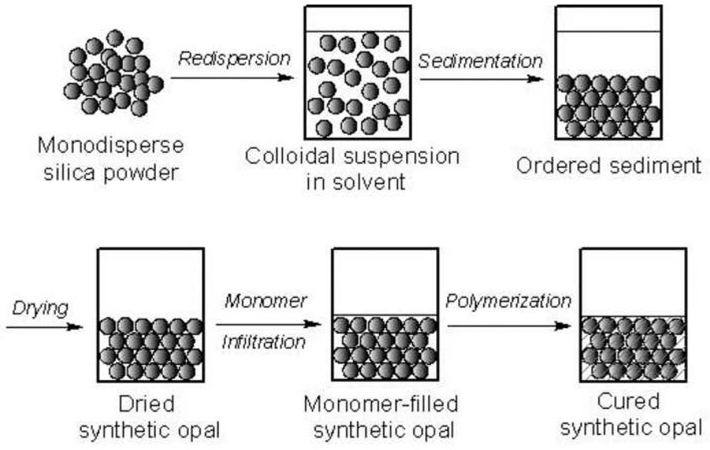
Figure 1a shows an exemplary method of making a wet colloidal crystal sample (e.g. with 60 wt% silica). 0.6 g of silica powder was added to 0.4 g of TEGDMA (pre-dissolved with initiators). At least three cycles of vortex shaking (~ 2 hours each) and manual spatulation (~1/2 hour each) were carried out until no solid clumps were detected by the naked eye. A “fully” dispersed silica suspension in TEGDMA was flowable and translucent, and showed angle-dependent iridescence immediately.
Figure 1.
Schematics of sample preparation for (a) wet colloidal crystals and (b) synthetic opals.
An exemplary method of making a synthetic opal sample is described as follows (Figure 1b). 1 g of silica powder was added into 1 g of appropriate solvent (e.g. water) followed by vigorous mixing, shaking and sonication. Subsequently, the temporary dispersion was let stand without any disturbance for as long as 1 week. Opalescence was observed in the final ordered sediment. The sediment was then dried by slow evaporation of the solvent followed by vacuum drying. Next, the sediment was infiltrated by initiator-added TEGDMA by first adding the monomer to the dried sediment and then putting the mixture in vacuum.
The solidification of the composites was achieved by either photo- or thermally-initiated free radical polymerization of the resin. We used camphorquinone (CQ, 0.5 wt%)/dimethylaminoethyl methacrylate (DMAEMA, 0 or 0.5 wt%) as the photoinitiator system, and azobisisobutyronitrile (AIBN, 0.1 wt%) as the thermal initiator, respectively. Photopolymerization was carried out in a visible light curing oven (TRIAD II, model TCU-II, 600 W, Dentsply/York Division, York, PA) for 10 minutes. Thermally initiated polymerization was carried out at ~ 55 °C for overnight.
2.5. Microscopic studies
The structure of a liquid dispersion of monodisperse silica (500 nm, 60 wt%) in TEGDMA was initially examined by using an optical microscope (Nikon Eclipse 400) with an oil immersion lens. A specimen was prepared by simply sandwiching a drop of the above dispersion between a glass slide and a cover glass. Fracture surfaces of solidified composite samples were characterized by scanning electron microscopy (FEI XL30 ESEM) using high vacuum mode. Samples were sputter-coated with Au/Pd.
2.6. Evaluation of mechanical properties
Compression tests (ASTM D-695) for both ordered and non-ordered composite samples were carried out on a servo-hydraulic tensile testing machine (MTS Mini-Bionix 2, Eden Prairie, MN) with a cross-head speed of 1 mm/min. For comparison purposes, neat resin samples of TEGDMA with or without DMAEMA were also prepared. All the compression specimens were molded and cured in cylindrical glass tubes (I.D. ~ 5 mm), and were cut into ~ 10 mm cylinders using a diamond saw. Photocured specimens were postcured in a ~ 37 °C oven for 24 hours before mechanical tests.
2.7. Thermogravimetric Analysis (TGA)
TGA curves of filler or composite samples were collected using a PerkinElmer Pyris 6 Thermogravimetric Analyzer. Samples were heated up from 30 to 1000 °C with a temperature ramp rate of 20 °C/min, and with air as sample purge gas (20 ml/min).
2.8. Fourier transform infrared spectroscopy (FTIR)
FTIR spectra of resin/composite samples before and after light curing were recorded with 16 scans at a resolution of 4 cm−1, using a PerkinElmer Spectrum 100 FTIR spectrometer with an attenuated total reflectance (ATR) accessory. The degree of double bond conversion (ξ) was calculated using the equation ξ = 1 – c/u, where c is the ratio of the absorbance intensity (peak height) of the methacrylate double bond (C=C, 1637 cm−1) to that of the internal reference (C=O, 1720 cm−1) after curing, and u is the same ratio for the uncured sample [28].
3. Results
3.1. Silica filler and its dispersibility in monomers/solvents
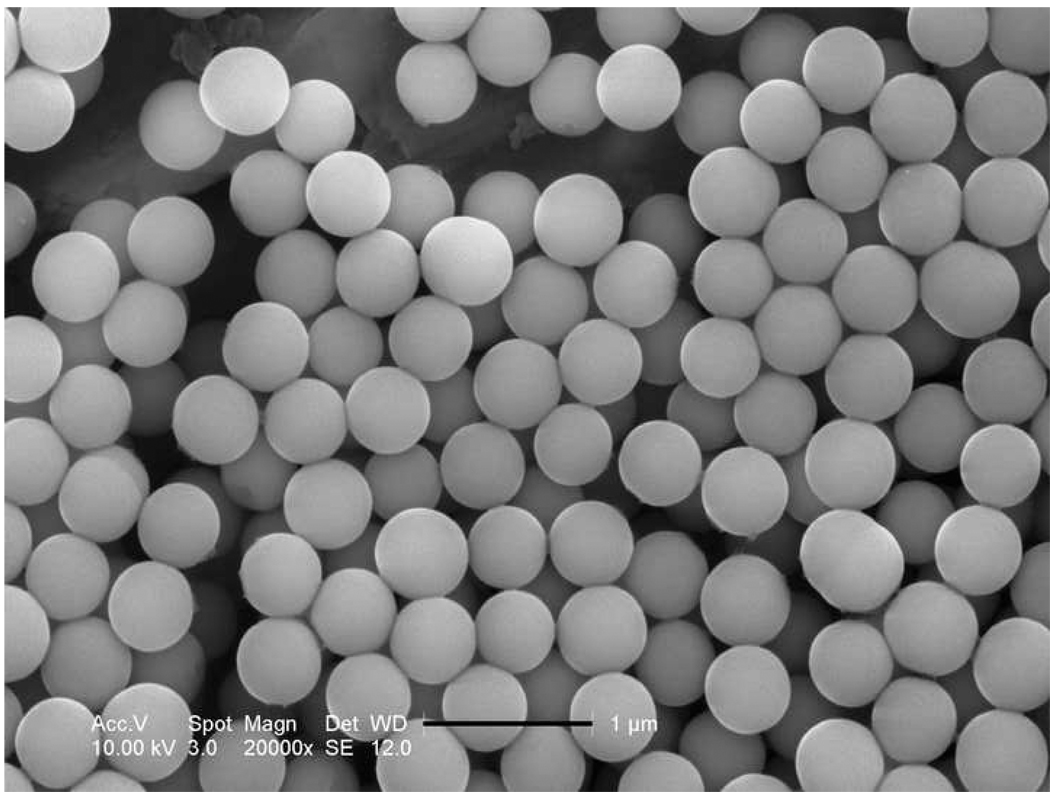
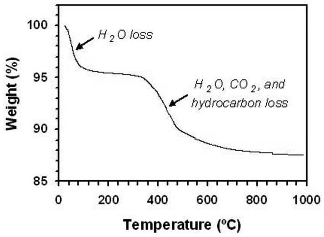
Our starting filler material was a dry silica powder composed of almost perfectly spherical particles with a diameter of ~ 500 nm (Figure 2). By analyzing monolayers of the spheres using ImageJ [29, 30], the polydispersity of these beads was found to be ~ 5 %. TGA (Figure 3) showed a two-step weight loss (~12 wt%) of the as-received silica powder, consisting of water (~ 4.6 wt%) and an organic component (~ 7.6 wt%).
Figure 2.
SEM micrograph of as-received silica particles, scale bar 1 micron.
Figure 3.
TGA weight loss curve for as-received silica particles.
To make ordered composites through colloidal crystallization, it was necessary to re-disperse the particles. Table 1 summarizes a qualitative evaluation of over ten solvents/monomers for their ability to suspend silica particles. We found that silica beads form a stable dispersion in TEGDMA. The dispersion appeared milky and translucent, and revealed angle-dependent iridescence from its top layer, suggesting crystallization of the silica spheres. We termed such a dispersion a “wet colloidal crystal”. Although a stable dispersion in MMA was also formed, no iridescence was observed. We found that though silica particles could slowly precipitate from temporary dispersions of most evaluated solvents, the sediments exhibited opalescence, indicating ordered packing of silica spheres, only when polar solvents such as water and alcohols were used. We termed such a sediment a “synthetic opal”.
3.2. Microscopic images of composites with ordered filler arrangement
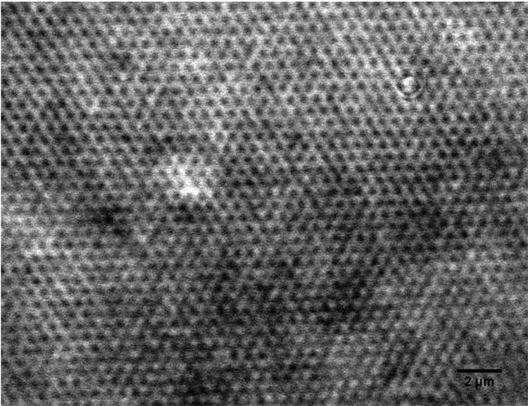
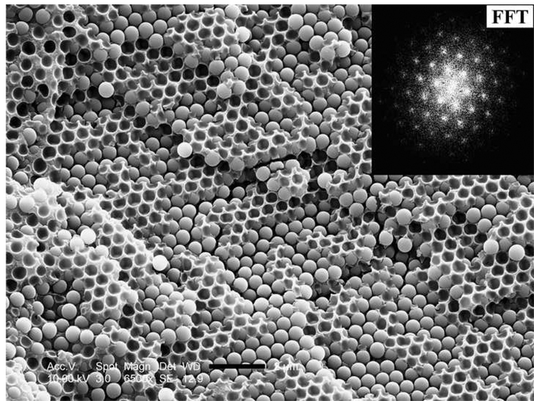
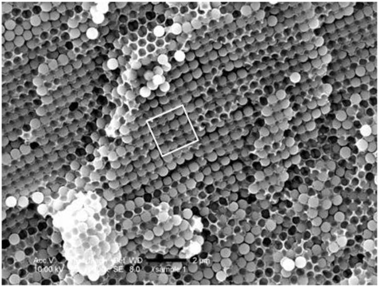
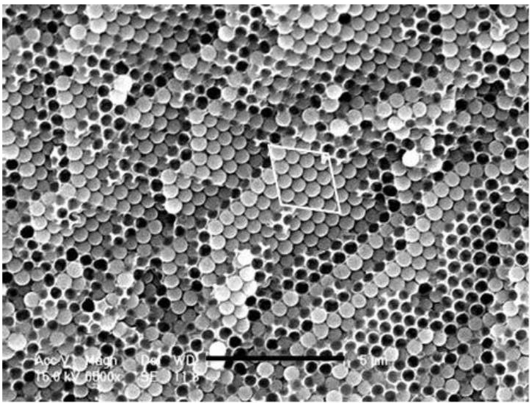
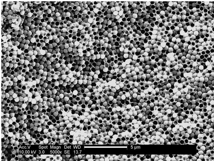
Figure 4a shows an optical micrograph of a wet colloidal crystal exhibiting a close-packed arrangement of silica spheres. Cured solid samples were examined by SEM. Figure 4b shows the microstructure of a cured wet colloidal crystal; again, we observed a close-packed structure that was preserved during polymerization. SEM pictures of a cured sample of synthetic opal are presented in Figure 4c and 4d. Based on literature data [17] and our preliminary studies, we believe that both our wet colloidal crystal and synthetic opal samples have a face-centered cubic (fcc) packed structure. Figure 4c features the (100) plane of the fcc structure, while Figure 4d shows the (111) plane of the fcc structure.
Figure 4.
a) Optical microscope picture of silica spheres (500 nm, 60 wt%) dispersed in TEGDMA, scale bar 2 microns. SEM micrographs (fracture surfaces) of (b) a cured wet colloidal crystal (60 wt% MPS-silica in TEGDMA), scale bar 1 micron. The inset shows the fast Fourier Transform (FFT) of the image; (c) a cured sample of synthetic opal featuring the (100) plane of the fcc ordered sample, scale bar 2 microns; (d) a cured sample of synthetic opal featuring the (111) plane of the fcc ordered sample, scale bar 5 microns.
3.3. Effects of DMAEMA and silane on filler ordering
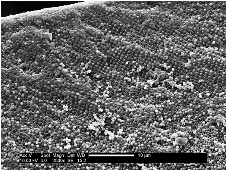
The tertiary amine DMAEMA, typically used as a co-initiator with CQ in visible light polymerization, was found to play a role in disrupting ordering in formulations containing as-received silica particles. An apparent increase in viscosity of such liquid formulations was observed, and after light-curing, the composites exhibited a non-ordered arrangement of silica as shown in Figure 5a. These observations were however not made with formulations where DMAEMA was absent. Figure 5b presents the SEM image of a cured composite sample containing 60 wt% as-received silica but without DMAEMA. An ordered arrangement is clearly shown in the picture, but such ordered areas are most likely located near the edges of the sample.
Figure 5.
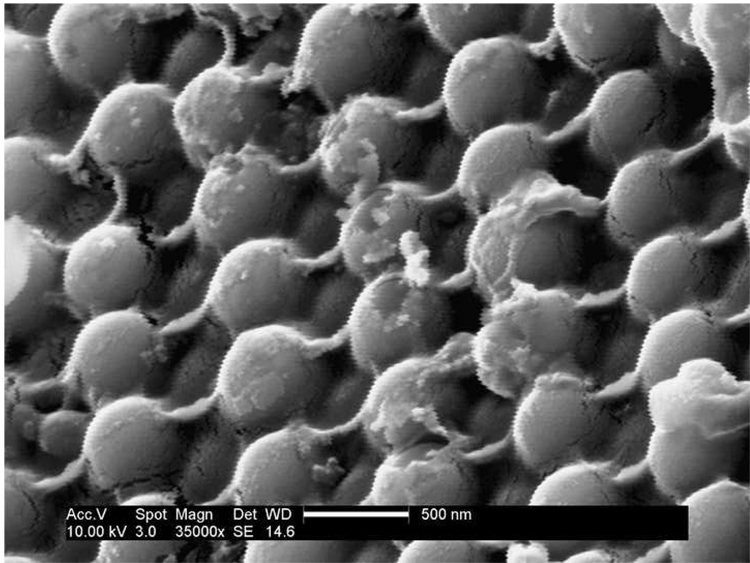
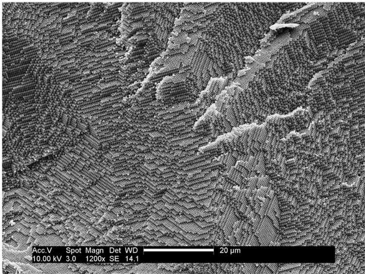
SEM micrographs (fracture surfaces) of cured composite (60 wt% in TEGDMA) samples containing (a) as-received silica and DMAEMA, scale bar 5 microns; (b) as-received silica but without DMAEMA, scale bar 10 microns; (c) MPS-silica and DMAEMA, scale bar 500 nm; (d) MPS-silica and DMAEMA, scale bar 20 microns.
For samples containing MPS-silanized silica particles, well-ordered arrays were always observed even if DMAEMA was present (Figure 5c and 5d). The rough surface on the silica particles (Figure 5c) indicates efficient MPS silane coating. At much lower magnification (Figure 5d), the ordered area is found to expand at least to 100 µm. By navigating the SEM sample stage, we estimate that the size of the ordered area is on a millimeter scale.
3.4. Effect of DMAEMA on mechanical properties
Compression tests were carried out for both ordered (wet colloidal crystal in this case) and non-ordered composite specimens. All composite samples used as-received (i.e. no silane coating) silica beads as filler (60 wt%) and contained CQ (0.5 wt%). The only difference was that the non-ordered sample contained 0.5 wt% DMAEMA, while there was no DMAEMA in the ordered sample. For comparison purposes, neat resin samples of TEGDMA with or without DMAEMA were also prepared. Although the ASTM standard doesn’t provide a direct way to measure toughness from compression tests, we estimated the toughness as the integrated area under the stress-strain curve [19]. Results are presented in Table 2.
Table 2.
Mechanical properties (in compression) of neat resins and monodisperse, non-silanized silica-filled composites
| TEGDMA (with 0.5 wt% DMAEMA) | TEGDMA (no DMAEMA) | Non-ordered Composite (with 0.5 wt% DMAEMA) | Ordered Composite (no DMAEMA) | |
|---|---|---|---|---|
| Modulus (GPa) | 1.91 (0.11) | 1.88 (0.24) | 4.92 (0.30) | 4.49 (0.48) |
| Failure Strain (%) | 29 (2.9) | 29 (4.7) | 8.3 (1.2) | 14.2 (2.5) |
| Compressive Strength (MPa) | 198.9 (26.7) | 220.7 (56.3) | 165.4 (21.2) | 192.1 (17.2) |
| Toughness* (J/m3 × 107) | 3.12 (0.65) | 3.05 (0.86) | 0.77 (0.31) | 1.81 (0.48) |
Toughness was calculated as the integrated area under the stress-strain curve[19].
For the neat resins, separate one-way analyses of variance (equivalent to two-sided t-tests) indicated that DMAEMA had no significant effect on properties. The two neat resins have nearly the same modulus and failure strain, and similar compressive strength (within the range of experimental error). For the composite material, the presence of DMAEMA had a clearly significant effect (p<0.05) for failure strain, compressive strength, and toughness, and a marginally significant effect for modulus (p=0.12). The modulus of the ordered composite (without DMAEMA) is slightly lower than that of the non-ordered composite (with DMAEMA), though the difference again falls within experimental error. A significant increase (16 %) in compressive strength and an impressive increase (71 %) in failure strain were observed for ordered composites compared to non-ordered composites. The toughness of the ordered composite more than doubled (235 %), consistent with its higher compressive strength and failure strain.
4. Discussion
4.1. Monodisperse filler and colloidal crystallization
In an analogy with atomic and molecular crystals, where atoms and molecules are the repeating structural units, the essential component for forming a colloidal crystal is a collection of colloidal particles with monodispersity better than 8 % [31]. Starting from Stöber-silica dispersions, Ford and coworkers reported a lengthy method (up to 20 days) resulting in ordered polymer-silica composite films (thickness < 1 mm), involving multiple dialysis steps to transfer silica particles into a monomer medium such as MMA [32]. We chose a dry silica powder as our starting material to reduce processing time. The size of the selected particles (~ 500 nm) proved convenient in three ways. First, it was in a size range (300 ~ 550 nm) that enabled a reasonable (< 2 weeks) settling speed (governed by Stokes law) for synthetic opal [33]; second, it was large enough to be initially observable by optical microscopy; third, with the size comparable to visible light wavelengths (400 ~ 800 nm), the iridescence/opalescence originating from Bragg diffraction was a strong indicator of ordering. The immediate challenge associated with using a dry powder was to demonstrate that this powder could be re-dispersed into suitable media for subsequent colloidal crystallization. As shown in Table 1, we found that high solvent polarity was required to form an ordered sediment (synthetic opal). This was reasonable, since the initial formation of discrete silica particles, rather than aggregates, was necessary for colloidal crystallization, and strong interactions (e.g. H-bond, dipole-dipole interaction) between particles and solvent molecules favored dissociation of particle aggregates. We also found that silica beads form a stable and iridescent dispersion (wet colloidal crystal) in TEGDMA over a wide range of silica content (30 ~ 70 wt%). It is not exactly clear why such a stable wet colloidal dispersion does not occur in the other solvent or monomer systems. Even in MMA, only a stable but non-iridescent dispersion was formed. One drawback of the silica particles we used, however, is the considerable amount of organic component (Figure 3), possibly from incomplete hydrolysis during the Stöber process.
4.2. Role of DMAEMA
In early efforts to prepare ordered composites, we incorporated DMAEMA (0.5 wt%) as the co-initiator with CQ, as this is common practice in light-curable composites. As a co-initiator, DMAEMA acts as a hydrogen-donor in the H-abstraction reaction with CQ during light initiation [34, 35]. We later found that DMAEMA had played a more complex role. Although the as-received silica dispersion in TEGDMA showed iridescence (Table 1) and optical microscopy (Figure 4a) confirmed close-packed structures, all early light-curable formulations (wet colloidal crystal) containing as-received silica and TEGDMA with CQ/DMAEMA failed to yield an ordered filler arrangement (see Figure 5a). Apparently, the addition of the initiators disrupted ordering. Figures 5 b ~ d show, however, that ordering exists in all formulations (with or without DMAEMA) containing MPS-silanized silica and in formulations containing as-received silica but without DMAEMA. These observations can be explained through the competing filler-filler and filler-resin interactions among filler (silica) particles and resin (TEGDMA) molecules. In chromatography where silica-based columns are used [36], basic amines were commonly used as a type of silanol-blocking agent, since they can form robust complexes with acidic silanol groups on silica surfaces through hydrogen bonding. In our materials, DMAEMA molecules are expected to partially block the silanol groups on as-received silica particles. Consequently, silica-TEGDMA interaction may be reduced, and silica-silica interaction and thus silica aggregates became favored. The formation of aggregates is also consistent with increased dispersion viscosity. On the other hand, silane molecules are well-known for the ability to prevent particle aggregation by providing steric repulsion between particles and enhancing filler-resin interaction. Therefore, we found better ordering in formulations with MPS-treated silica.
4.3. Effect of DMAEMA on mechanical properties
We want to emphasize that the significant differences in mechanical properties (Table 2) between composites with or without DMAEMA are not due to differential resin polymerization. We believe that any effect of DMAEMA on resin polymerization was minor under our experimental conditions, especially with prolonged light exposure (10 min). A small fraction of TEGDMA molecules could take the place of DMAEMA by supplying H during the H-abstraction reaction with light-excited CQ through their ether linkages and therefore generate active free radicals to initiate polymerization. Also, after prolonged light exposure, the degree of double bond conversion should eventually be kinetically limited by increased TEGDMA viscosity which would be similar for both composite formulations. The H-donating ability of TEGDMA and diffusion controlled monomer conversion were confirmed in a study by Andrzejewska et al [37]. In fact, the degrees of resin double bond conversion determined by FTIR for composite samples with or without DMAEMA were found nearly the same (~ 48 %). We also verified by TGA that the filler contents for both composite samples were the same, i.e. ~ 55 wt% after heating to 1000 °C. We conclude that the significantly enhanced mechanical properties in wet colloidal crystal samples without DMAEMA are attributable to the unique structural feature, i.e., non-aggregated and ordered filler arrangement in the composites. Although hierarchically ordered structures have been well-recognized in many living organisms, and efforts to mimic such structures to obtain desirable optical and magnetic material properties, we are not aware of any elaborate theory that addresses the effect of 3-D filler arrangement on mechanical properties of composites. In previous modeling studies, however, we have reported that periodic particle arrangements predict less stress concentration than a random particle arrangement, which might partially account for the better mechanical properties observed in our ordered systems [38].
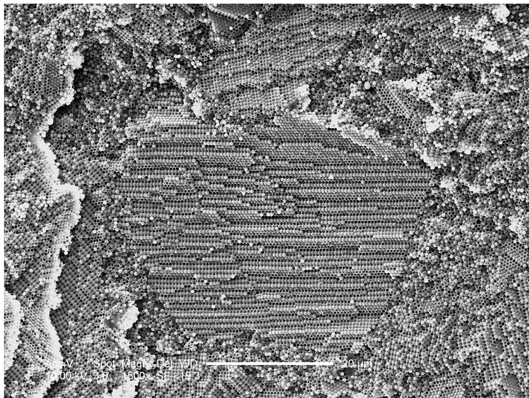
Parenthetically, we have demonstrated that prior to polymerization the monomer-infiltrated synthetic opal samples (see Figure 1b) can be compacted into a simulated 2 × 4 mm diameter “cavity”, and the subsequently cured samples still possess ordered features, though in polycrystalline form (shown in Figure 6).
Figure 6.
SEM micrograph (fracture surface) of a cured composite sample through direct filling of monomer-infiltrate synthetic opal, scale bar 20 microns.
5. Conclusion
Two complementary synthetic routes have been developed to prepare dental composite materials with an ordered filler arrangement. DMAEMA plays a role in disrupting ordered filler particle ordering in composites containing non-treated silica, while MPS-silanized samples exhibit more highly ordered structures. Our mechanical evaluation results indicate that ordering leads to significantly increased compressive strengths and failure strains and may thus provide a strategy to prepare novel composite materials.
Acknowledgements
The support of NIH through grant R21DE018330 is gratefully appreciated. We thank Esstech for the donation of resin materials.
Footnotes
Publisher's Disclaimer: This is a PDF file of an unedited manuscript that has been accepted for publication. As a service to our customers we are providing this early version of the manuscript. The manuscript will undergo copyediting, typesetting, and review of the resulting proof before it is published in its final citable form. Please note that during the production process errors may be discovered which could affect the content, and all legal disclaimers that apply to the journal pertain.
REFERENCES
- 1.Moszner N, Salz U. New developments of polymeric dental composites. Progress in Polymer Science. 2001;26:535–576. [Google Scholar]
- 2.Klapdohr S, Moszner N. New inorganic components for dental filling composites. Monatshefte fuer Chemie. 2005;136:21–45. [Google Scholar]
- 3.Currey JD. Materials science: Hierarchies in biomineral structures. Science. 2005;309:253–254. doi: 10.1126/science.1113954. [DOI] [PubMed] [Google Scholar]
- 4.Mayer G. Rigid biological systems as models for synthetic composites. Science. 2005;310:1144–1147. doi: 10.1126/science.1116994. [DOI] [PubMed] [Google Scholar]
- 5.Jiang H, Liu X-Y, Lim CT, Hsu CY. Ordering of self-assembled nanobiominerals in correlation to mechanical properties of hard tissues. Applied Physics Letters. 2005;86:163901/163901–163901/163903. [Google Scholar]
- 6.Caruso F, Spasova M, Saigueirino-Maceira V, Liz-Marzán LM. Multilayer assemblies of silica-encapsulated gold nanoparticles on decomposable colloid templates. Advanced Materials. 2001;13:1090–1094. [Google Scholar]
- 7.Tolbert SH, Firouzi A, Stucky GD, Chmelka BF. Magnetic field alignment of ordered silicate surfactant composites and mesoporous silica. Science (Washington, D. C.) 1997;278:264–268. [Google Scholar]
- 8.Park C, Robertson RE. Aligned microstructure of some particulate polymer composites obtained with an electric field. Journal of Materials Science. 1998;33:3541–3553. [Google Scholar]
- 9.Buxton GA, Balazs AC. Simulating the morphology and mechanical properties of filled diblock copolymers. Physical Review E: Statistical, Nonlinear, and Soft Matter Physics. 2003;67:031802/031801–031802/031812. doi: 10.1103/PhysRevE.67.031802. [DOI] [PubMed] [Google Scholar]
- 10.Lee J-Y, Thompson RB, Jasnow D, Balazs AC. Entropically driven formation of hierarchically ordered nanocomposites. Physical Review Letters. 2002;89:155503/155501–155503/155504. doi: 10.1103/PhysRevLett.89.155503. [DOI] [PubMed] [Google Scholar]
- 11.Peng G, Qiu F, Ginzburg VV, Jasnow D, Balazs AC. Forming supramolecular networks from nanoscale rods in binary, phase-separating mixtures. Science (Washington, D. C.) 2000;288:1802–1804. doi: 10.1126/science.288.5472.1802. [DOI] [PubMed] [Google Scholar]
- 12.Bockstaller MR, Mickiewicz RA, Thomas EL. Block copolymer nanocomposites: Perspectives for tailored functional materials. Advanced Materials (Weinheim, Germany) 2005;17:1331–1349. doi: 10.1002/adma.200500167. [DOI] [PubMed] [Google Scholar]
- 13.Bockstaller MR, Lapetnikov Y, Margel S, Thomas EL. Size-selective organization of enthalpic compatibilized nanocrystals in ternary block copolymer/particle mixtures. Journal of the American Chemical Society. 2003;125:5276–5277. doi: 10.1021/ja034523t. [DOI] [PubMed] [Google Scholar]
- 14.Chung H-j, Ohno K, Fukuda T, Composto Russell J. Self-regulated structures in nanocomposites by directed nanoparticle assembly. Nano Lett. 2005;5:1878–1882. doi: 10.1021/nl051079e. [DOI] [PubMed] [Google Scholar]
- 15.Pusey PN, Van Megen W. Phase behavior of concentrated suspensions of nearly hard colloidal spheres. Nature (London, United Kingdom) 1986;320:340–342. [Google Scholar]
- 16.Pusey PN, Vanmegen W, Bartlett P, Ackerson BJ, Rarity JG, Underwood SM. Structure of crystals of hard colloidal spheres. Physical Review Letters. 1989;63:2753–2756. doi: 10.1103/PhysRevLett.63.2753. [DOI] [PubMed] [Google Scholar]
- 17.Xia Y, Fudouzi H, Lu Y, Yin Y. Colloidal crystals. Recent developments and niche applications. Colloids and Colloid Assemblies. 2004:284–316. [Google Scholar]
- 18.Xia Y. Photonic crystals. Advanced Materials (Weinheim, Germany) 2001;13:369. [Google Scholar]
- 19.Pu Z, Mark JE, Jethmalani JM, Ford WT. Effects of dispersion and aggregation of silica in the reinforcement of poly(methyl acrylate) elastomers. Chemistry of Materials. 1997;9:2442–2447. [Google Scholar]
- 20.Lepizzera S, Scheer M, Fond C, Pith T, Lambla M, Lang J. Coalesced core/shell latex films under elongation imaged by atomic force microscopy. Macromolecules. 1997;30:7953–7957. [Google Scholar]
- 21.Foulger SH, Jiang P, Ying Y, Lattam AC, Smith DW, Jr, Ballato J. Photonic bandgap composites. Advanced Materials (Weinheim, Germany) 2001;13:1898–1901. [Google Scholar]
- 22.Fava D, Fan YS, Kumacheva E, Winnik MA, Shinozaki DM. Order versus disorder: Effect of structure on the mechanical properties of polymer material. Macromolecules. 2006;39:1665–1669. [Google Scholar]
- 23.Pefferkorn A, Pefferkorn E, Haikel Y. Influence of the colloidal crystal-like arrangement of polymethylmethacrylate bonded aerosit particles on the polymerization shrinkage of composite resins. Dental Materials. 2006;22:661–670. doi: 10.1016/j.dental.2005.08.005. [DOI] [PubMed] [Google Scholar]
- 24.Wan Q, Baran GR, Kulkarni S, Praveen S. Bio-inspired polymer dental composites with ordered filler arrangement. PMSE Preprint, 232nd ACS National Meeting; San Francisco, CA. 2006. [Google Scholar]
- 25.Liu Q, Ding J, Chambers DE, Debnath S, Wunder SL, Baran GR. Filler-coupling agent-matrix interactions in silica/polymethylmethacrylate composites. Journal of Biomedical Materials Research. 2001;57:384–393. doi: 10.1002/1097-4636(20011205)57:3<384::aid-jbm1181>3.0.co;2-f. [DOI] [PubMed] [Google Scholar]
- 26.Debnath S, Wunder SL, McCool JI, Baran GR. Silane treatment effects on glass/resin interfacial shear strengths. Dental Materials. 2003;19:441–448. doi: 10.1016/s0109-5641(02)00089-1. [DOI] [PubMed] [Google Scholar]
- 27.Zhuravlev LT. The surface chemistry of amorphous silica. Zhuravlev model. Colloids and Surfaces a-Physicochemical and Engineering Aspects. 2000;173:1–38. [Google Scholar]
- 28.Shin WS, Li XF, Schwartz B, Wunder SL, Baran GR. Determination of the degree of cure of dental resins using Raman and FT-Raman spectroscopy. Dental Materials. 1993;9:317–324. doi: 10.1016/0109-5641(93)90050-z. [DOI] [PubMed] [Google Scholar]
- 29.Rasband W. Bethesda, Maryland, USA: U.S. National Institutes of Health; ImageJ. 1997–2006 http://rsb.info.nih.gov/ij.
- 30.Abramoff M, Magelhaes P, Ram S. Image processing with ImageJ. Biophotonics International. 2004;11:36–42. [Google Scholar]
- 31.Imhof A. Three-dimensional photonic crystals made from colloids. In: Liz-Marzán LM, Kamat PV, editors. Nanoscale Materials. Boston/Dordrecht/London: Kluwer Academic Publishers; 2003. pp. 423–454. [Google Scholar]
- 32.Sunkara HB, Jethmalani JM, Ford WT. Composite of Colloidal Crystals of Silica in Poly(methyl methacrylate) Chemistry of Materials. 1994;6:362–364. [Google Scholar]
- 33.Holgado M, Garcia-Santamaria F, Blanco A, Ibisate M, Cintas A, Miguez H, Serna CJ, Molpeceres C, Requena J, Mifsud A, Meseguer F, Lopez C. Electrophoretic deposition to control artificial opal growth. Langmuir. 1999;15:4701–4704. [Google Scholar]
- 34.Fouassier JP, Allonas X, Burget D. Photopolymerization reactions under visible lights: principle, mechanisms and examples of applications. Progress in Organic Coatings. 2003;47:16–36. [Google Scholar]
- 35.Jakubiak J, Allonas X, Fouassier JP, Sionkowska A, Andrzejewska E, Linden LA, Rabek JF. Camphorquinone-amines photoinitating systems for the initiation of free radical polymerization. Polymer. 2003;44:5219–5226. [Google Scholar]
- 36.Reta M, Carr PW. Comparative study of divalent metals and amines as silanol-blocking agents in reversed-phase liquid chromatography. Journal of Chromatography A. 1999;855:121–127. doi: 10.1016/s0021-9673(99)00638-x. [DOI] [PubMed] [Google Scholar]
- 37.Andrzejewska E, Linden LA, Rabek JF. The role of oxygen in camphorquinone-initiated photopolymerization. Macromolecular Chemistry and Physics. 1998;199:441–449. [Google Scholar]
- 38.Sun CJ, Saffari P, Sadeghipour K, Baran G. Effects of particle arrangement on stress concentrations in composites. Materials Science and Engineering a-Structural Materials Properties Microstructure and Processing. 2005;405:287–295. [Google Scholar]


