

Abstract
Hybrid supramolecular architectures have been fabricated with acceptor 1,4-bis(4-pyridylethynyl)-2,3-bis-dodecyloxy-benzene (PBP) and donor 2,6-bis(3,4,5-tris-dodecyloxy-phenyl)dithieno[3,2-b:2′,3′-d]thiophene (DTT) compounds on highly oriented pyrolytic graphite (HOPG) surfaces and their structures and molecular conductance are characterized by scanning tunneling microscopy/spectroscopy (STM/STS). Stable, one-component adlayers of PBP and DTT are also investigated. The coadsorption of two-component mixtures of PBP and DTT results in a variety of hybrid nanopattern architectures that differ from those of their respective one-component surface assemblies. Adjusting the acceptor/donor molar ratio in mixed adlayer assemblies results in dramatic changes in the structure of the hybrid nanopatterns. STS measurements indicate that the HOMO and LUMO energy levels of PBP and DTT on an HOPG surface are relatively insensitive to changes in the hybrid supramolecular architectures. These results provide important insight into the design and fabrication of two-dimensional hybrid supramolecular architectures.
1. Introduction
Self-organization and self-assembly play important roles in the so-called “bottom-up” strategy of nanofabrication.1-6 The design and control of specifically patterned self-assembled adlayers on two-dimensional (2D) surfaces has led to a variety of promising candidates for applications in nanoelectronic, sensor and molecular devices.7-11 Recently, the formation, structures and properties of different self-assembled adlayers have been intensively investigated. The use of powerful observation techniques such as scanning tunneling microscopy (STM) has enabled thorough investigations of the influence of solvent, chemical structure, substrate and temperature on adlayer self-assembly to be performed.12-21 Following from these successes in observation there is now a shift toward exhibiting greater control over adlayer formation and architecture. Successful structural control requires that the intermolecular adsorbate-adsorbate and substrate-adsorbate interactions be studied and rationally employed in adlayer design. By carefully balancing these interactions, well-defined adlayer self-assemblies can be formed on different substrates and in different environments by physical and chemical methods. Furthermore, beyond one-component surface self-assembly, multi-component assemblies arising from molecular coadsorption have also attracted much interest due to their inherently increased structural diversity and highly variable properties, which make hybrid adlayer assemblies even more attractive for potential materials applications. For example, the concept of using bulk heterojunctions has been successfully applied in the design and fabrication of organic solar cells.22, 23 Meissener et al. have used a mixed adlayer of a fullerene (C60) acceptor and a phthalocyanine (ZnPc) donor in a heterojunction solar cell to achieve a power conversion efficiency of 1%. Moreover, donor/acceptor bilayer solar cells have also been developed.23-27 It is well known that the performance of organic semiconductors in molecular electronic devices depends, at least in part, on their supramolecular organization and morphology. Understanding the structure of multi-component assemblies is crucial for improving device performance.
In this article we report the design and preparation of a series of hybrid nanopattern adlayer assemblies from a two-component donor/acceptor system and have imaged their molar-ratio dependent structures with STM. Although binary self-assemblies of host/guest systems have been reported the literature,28-31 there have been few reports investigating the hybrid self-assembly of donor/acceptor systems. Furthermore, there are no reports concerning the influence of the relative ratio(s) of donor to acceptor on resulting hybrid nanopatterns. We have used 1,4-bis(4-pyridylethynyl)-2,3-bis-dodecyloxy-benzene (PBP) as an acceptor32 and 2,6-bis(3,4,5-tris-dodecyloxy-phenyl)dithieno[3,2-b:2′,3′-d]thiophene (DTT) as a donor (Figure 1) to fabricate well-ordered donor/acceptor hybrid nanopatterns on highly oriented pyrolytic graphite (HOPG) surfaces. Upon changing the acceptor/donor molar concentration ratio, various hybrid supramolecular architectures are observed each with different lattice parameters, molecular arrangements and molecular orientations within the adlayer. Adjusting the acceptor/donor molar concentration ratio allows for the balance between intermolecular adsorbate-adsorbate and adsorbate-substrate interactions to be adjusted and results in the formation of controllable nanopatterns.
Figure 1.

Chemical structure, molecular size and calculated HOMO/LUMO orbitals (dodecyl substituents are replaced by methyl substituents for ease of calculation) of PBP (left column) and DTT (right column), R= C12H25. The molecules adopt linear and bent conformations, respectively.
2. Experimental section
PBP was prepared according to literature proceedures.33 DTT was synthesized by coupling two equivalents of 5-bromo-1,2,3-tris(dodecyloxy)benzene34 with a bis(tributyltin) thiophene derivative35 as shown in Scheme 1. The details can be seen in the Supporting Information. Dilute (10−4 M) toluene solutions of each compound were prepared and used in the preparation, by solution-deposition, of adlayers on HOPG. Solution concentrations higher than 10-3 M resulted in aggregation of the PBP and DTT into disordered clusters on HOPG as observed by STM. Hybrid structures were prepared by mixing specific ratios (volume:volume) of the two solutions of PBP and DTT of initial 10-4 M concentration. DTT adsorbs more strongly on HOPG than PBP does due to the greater number of dodecyl chains:36-38 six for DTT versus two for PBP. Therefore, hybrid architectures could only be obtained with PBP:DTT concentration ratios of ranging from 2:1 to 100:1. This phenomenon demonstrates competitive adsorption in a binary system.
Scheme 1.

Synthetic protocol used to prepare DTT.
For self-assembled adlayer formation and subsequent STM observation, a drop of either pure 10−4 M single-component or pre-prepared multi-component solution was deposited onto a freshly cleaved surface of HOPG (quality ZYB, Digital Instruments). Following evaporation of the solvent, a self-assembled monolayer was formed and used for STM/STS measurements. Single monolayer formation, as opposed to multilayer formation, was confirmed by STM measurements of corrugation height profiles39 (see Supporting Information). The samples were observed by using NanoScope IIIa (Digital Instruments) and PicoScan (Agilent MI) scanning tunneling microscopes. The tunneling tips were prepared by mechanically cutting Pt/Ir wire (90/10). All the STM images were recorded in the constant-current mode. STS measurements were performed by applying a modulation to the bias voltage. A lock-in amplifier was used to collect dI/dV-V signals. The feedback of STM control was turned off during STS measurements. Further details of STM and STS experiments can be found in the literature.40-42
3. Results and discussion
3.1. DTT Assembly
An STM image of a pure DTT self-assembled adlayer on HOPG is shown in Figure 2a. The large-scale image shows a well resolved ordered pattern of bright stripes and dark troughs. The bright stripes are ascribed to the π-conjugated backbones of DTT, while the dark troughs are the alkyl chains. A fault dislocation, where a row of molecules takes a different orientation from its neighboring rows, is seen in the molecular row indicated by arrow A. However, a long-range ordering with well-defined structural characteristics is still observed in the adlayer. Figure 2b is a high-resolution STM image, revealing the structural details of the adlayer. It is clear that the bright stripes are composed of well-separated, slightly curved rods. The length of each bright rod is 1.7 ± 0.2 nm, in agreement with the theoretical value of the π-conjugated backbone of DTT. Therefore, each bright rod in the STM images corresponds to a DTT molecule. A composite STM image showing both the DTT monolayer and the underlying HOPG surface (see Figure S2 of the Supporting Information) was created by varying the tunneling bias in order to determine their relative orientation. It is found that the π-conjugated backbone forms an angle of roughly 90° with HOPG substrate. Moreover, the distance between neighboring stripes, i.e. the dark troughs, is 1.5 ± 0.2 nm. This value matches well, within experimental error, with the length of fully extended decyloxy chains (1.5 nm). This observation indicates that the alkyl chains of the neighboring DTT molecules are interdigitated with each other. For clarity, four DTT molecules are superimposed in Figure 2b. In accordance with the high resolution STM image, a structural model is proposed for the ordered DTT assembly in Figure 2c. The lattice constants are determined to be a = 4.0 ± 0.2 nm, b = 2.0 ± 0.2 nm, and α = 45 ± 2°.
Figure 2.

Adlayer structure of DTT on an HOPG surface prepared by deposition of a 10-4 M toluene solution of DTT. (a) Large scale STM image. Itip = 355 pA, Vbias = -600 mV. (b) High resolution STM image. Itip = 578 pA, Vbias = -564 mV. (c) Proposed structural model of the DTT assembly. A set of arrows indicates the underlying HOPG lattice direction, revealing the relative orientation of the DTT molecules with respect to the HOPG lattice.
While the well-defined structure shown in Figure 2 was commonly observed, an alternative pure DTT adlayer structure different from that in Figure 2 was also observed locally. Figure 3a is an STM image of the different adlayer structure of DTT on HOPG. Several domains can be seen in the image. The structural details are revealed in the high-resolution STM image (Figure 3b). The adlayer structure retains the characteristics of bright π-conjugated backbones and dark troughs of alkyl chains that were observed in the extended adlayer shown in Figure 2. In the smaller, local adlayer of Figure 3, however, DTT molecules are packed side-by-side and form a dimeric structure different from the structure in Figure 2. The length of an individual bright rod is 1.7 ± 0.2 nm, consistent with the theoretical length of the molecular backbone of DTT. From the molecular arrangement and intermolecular interactions, a structural model for the ordered monolayer is proposed in Figure 3c. A unit cell is outlined in Figures 3b and 3c. The lattice constants of the unit cell are determined to be a = 4.0 ± 0.2 nm, b = 3.7 ± 0.2 nm, and α = 80 ± 2°. The coverage of the two structures in Figures 2 and 3 is roughly the same. While the formation of the DTT adlayer shown in Figure 2 appears to be driven, primarily, by van der Waals interactions between the interdigitated dodecyloxy chains, the DTT adlayer of Figure 3 is formed through a combination of van der Waals contacts between dodecyloxy chains and also between the π-conjugated backbone of DTT. The results indicate that different molecular interactions can give rise to different, well-formed adlayers of the same molecule deposited at the same concentration on the same surface. A similar 2D polymorphism phenomena has also been observed by Metzger et al.43
Figure 3.

Alternative adlayer structure of DTT on HOPG. (a) Large scale STM image. Itip = 400 pA, Vbias = -600 mV. (b) High-resolution STM image. Itip = 400 pA, Vbias = -400 mV. (c) Proposed structural model for the DTT assembly in (a) and (b). A set of arrows indicates the underlying HOPG lattice, showing the orientation relative between the DTT molecules and the HOPG lattice.
3.2. PBP Assembly
Figure 4a shows a typical STM image of the PBP adlayer prepared by depositing a 10-4 M toluene solution of PBP on an HOPG surface. The molecules form a large and highly ordered domain in which alternating bright stripes and dark troughs can be resolved. From the chemical structure of PBP, the bright stripes are ascribed to the molecules' 1,4-bis(4-pyridylethynyl) benzene π-conjugated backbone while the dark troughs arise from the dodecyloxy chains. The structural details are revealed by a high-resolution STM image shown in Figure 4b. Each stripe from the large-scale STM image is resolved at higher resolution into two well-separated rows consisting of bright rods. The length of each individual bright rod is 1.6 ± 0.2 nm, comparable to the theoretical size of the molecular backbone. The backbones of PBP molecules pack side-by-side, forming a dimeric motif. In addition, the length of each dark trough is 1.5 ± 0.2 nm, in agreement with the size of the fully extended dodecyloxy alkyl chains. This indicates that the alkyl chains of PBP in neighboring rows interdigitate with each other. The spacing between the two molecules of each dimer is ca. 0.7 nm. Moreover, the PBP molecules alternately take a different orientation in neighboring molecular rows, with each row of dimers alternatively “tilting” in one direction or the other. For greater clarity of the adlayer, twelve PBP molecular models are superimposed in the STM image of Figure 4b. In this arrangement, the molecules form a dense close-packed and stable 2D network and reach an interaction balance between neighboring molecules. On the basis of the above analysis, a structural model has been derived for the PBP assembly and is shown in Figure 4c. A unit cell is outlined in both the STM image and the structural model. The lattice parameters in the unit cell are measured to be a = 6.3 ± 0.2 nm, b = 2.0 ± 0.2 nm, and α = 95 ± 2°. The self-assembled adlayer of PBP on an HOPG surface shown in Figure 4 exists over a range of solution concentrations from 10-4 to 10-5 M.
Figure 4.

Adlayer strucutre of PBP on an HOPG surface prepared from deposition of a 10-4 M toluene solution of PBP. (a) Large scale STM image. Itip = 603 pA, Vbias = 600 mV. (b) High-resolution STM image. Itip = 600 pA, Vbias = 600 mV. (c) Proposed structural model of the PBP assembly. A set of arrows indicates the orientation of the underlying HOPG lattice.
3.3 Hybrid supramolecular nanopatterns of PBP and DTT molecules
Following the STM examination of individual DTT and PBP self-assembled adlayers, a variety of hybrid molecular architectures of PBP and DTT were prepared by adjusting the relative volumetric ratios of 10-4 M toluene solutions of these two molecules. As the PBP:DTT ratio is increased, the balance of intermolecular (adsorbate-adsorbate) interactions and competitive coadsorption (surface-adsorbate interactions) result in a variety of different nanopatterned assemblies. In particular, the following hybrid nanopattern transformations were observed with an increasing ratio of PBP: pure DTT assembly → coexistence of rectangular hybrid nanopattern and pure DTT assembly → coexistence of rectangular and rhombic hybrid nanopatterns → pure rhombic hybrid nanopattern → extended rhombic hybrid nanopattern → pure PBP assembly. STM imaging allowed for the molecular orientation, structure and arrangement of the different nanopatterns to be revealed.
3.3.1. Coexistence of a rectangular hybrid nanopattern and pure DTT assembly
Initial multi-component assembly experiments involved the deposition of mixtures of PBP and DTT with only a small excess of the weaker adsorbing PBP acceptor. Under such conditions the coexistence of domains of a PBP:DTT hybrid adlayer and pure DTT adlayer was observed. Figure 5 is a typical large scale STM image of an ordered mixed-monolayer obtained by depositing a drop of toluene solution containing PBP and DTT (2:1) onto HOPG. In the image, two molecular domains can be seen within the scanning area, indicated as domains A and B, with the domain boundary shown by a dashed line. The domain boundaries appear to traverse at ca. 120° angles, suggesting epitaxy with the underlying HOPG substrate. Careful inspection reveals that the adlayer in the B domain has the same structure as that shown in Figure 3 and is composed entirely of DTT molecules. The dimeric feature can be clearly distinguished by pairs of bright rods in the image. As a result of competitive adsorption and the stronger adsorption of DTT on HOPG, DTT molecules form their own pure adlayer in domain B. Domain A, on the other hand, is composed of an entirely new well-ordered adlayer that is completely different from the structures observed in either pure DTT or PBP adlayers. The appearance of this new phase suggests the formation of a PBP:DTT hybrid structure that arises due to favorable adsorbate-adsorbate intermolecular interactions, which cause the PBP molecules to integrate with DTT molecules and organize into a multi-component 2D self-assembled molecular network
Figure 5.

A typical STM image showing the formation of a hybrid adlayer structure (domain A) of PBP and DTT molecules on HOPG. The dashed line indicates the domain boundary between hybrid structure (A) and the pure DTT adlayer (domain B). STM imaging condition: Itip = 457 pA, Vbias = -600 mV.
Figure 6a shows a typical STM image of the PBP:DTT hybrid structure obtained when a 2:1 ratio of PBP to DTT is deposited on HOPG. The structure is the same as that in domain A of Figure 5 and is easily reproduced. The image consists of two dominant structural motifs indicated by a red and a green oval in Figure 6a. According to the periodicity of the red and green ovals, a rectangular unit cell is outlined in the image. The lattice constants of the unit cell are determined to be a = 5.2 ± 0.2 nm, b = 11.2 ± 0.2 nm, and α = 90 ± 2°. The details of the internal structure, orientation, and packing arrangement of molecular backbones and alkyl chains are revealed in the high-resolution image in Figure 6b. The motif indicated by the green ovals is composed of two different bright protrusions, one linear and the other curved, which form an II-like rectangular shape. From the chemical structures of PBP and DTT, as well as the results of state density calculations (Figure 1), these features arise from two equivalents each of PBP and DTT. The two PBP molecules correspond to the bright, linear rods that are highlighted in red in Figure 6b, while white bent rods indicate the curved DTT molecules. Moreover, the bent protrusions corresponding to DTT molecules are slightly brighter than those of the linear PBP molecules in the STM image because the molecular backbones of DTT and PBP have different state densities, which subsequently result in different image contrast.
Figure 6.

Hybrid adlayer structure of PBP and DTT on an HOPG surface. (a) Large scale STM image. Itip = 750 pA, Vbias = 600 mV. (b) High-resolution STM image. Itip = 908 pA, Vbias = 600 mV. (c) Proposed structural model for the hybrid nanopattern structure. A set of arrows indicates the orientation of the underlying HOPG lattice.
The structural motif marked by the red oval in Figure 6b is more complex than that outlined by a green oval. Careful investigation of the high resolution STM image reveals that there are six DTT molecules and two PBP molecules in the structural motif indicated by the red oval. The alkyl chains of PBP and DTT are observed to interdigitate. The collection of intermolecular alkyl-aromatic and alkyl-alkyl interactions between PBP and DTT give rise to the overall well-ordered hybrid structure and form a stable 2D network. By varying the tunneling bias, the relative orientation of the hybrid monolayer and the underlying HOPG lattice can be observed (See Figure S3 in the Supporting Information) and the relationship between the molecular adlayer and the HOPG substrate can be determined. Molecular models of PBP and DTT are superimposed in Figure 6b to indicate the structural details of the hybrid nanopattern. A set of arrows indicates the orientation of the underlying HOPG lattice. On the basis of structural observations and the above analysis, a model of the adlayer is proposed in Figure 6c. The alkyl chains between neighboring molecules either interdigitate with each other or adopt a parallel configuration in order to achieve the closest packing density and to maximize adsorbate-adsorbate interactions. The proposed model is in good agreement with the high-resolution STM images in Figure 6b. From the model, it is clear that in a unit cell of the hybrid nanopatterned architecture there are four PBP molecules and eight DTT molecules, indicating a PBP:DTT ratio of 1:2. This ratio is the opposite of the 2:1 PBP:DTT molar ratio used during solution deposition to create the hybrid adlayer, thus further demonstrating the competitive, preferential adsorption of DTT on HOPG.
3.3.2. Coexistence of a hybrid rectangular/rhombic nanopatterns
Increasing the PBP:DTT concentration ratio to 20:1 results in the appearance of a different hybrid structure on the HOPG surface. Figures 7a and 7b are typical large scale and high-resolution STM images of adlayers formed in this concentration ratio range. In Figure 7a, a well-ordered molecular nanopattern extends over the HOPG surface. The domain size of the nanopattern extends over an area greater than 100 nm. It is clear from the image that the adlayer is composed of two types of structural motifs: a rectangular feature marked by a green oval and a rhombic feature indicated by a red oval. The structural details of these coexisting rectangular and rhombic hybrid nanopatterns can be seen in Figure 7b. The π-conjugated backbones and alkyl chains of the PBP and DTT molecules are clearly distinguished in the image, providing the structural information necessary for understanding the molecular adsorption and intermolecular interactions. The rectangular motif indicated by the green oval is composed of two PBP and two DTT molecules and is the same as the II-like rectangular structure observed in Figure 6. The other regularly repeating rhombic structural motif (indicated by a red oval) is also formed by four molecules – two equivalents of PBP and two equivalents of DTT - though the molecular arrangement in this motif is different from that seen in the rectangular motif. As discussed above, the bent and linear protrusions correspond to the molecular backbones of DTT and PBP molecules, respectively, in accordance with their chemical structure and state density. Molecular models are superimposed in Figure 7b and illustrate the structural and packing features of the hybrid nanopatterned adlayer. From the symmetry and periodicity of the hybrid nanopattern, a unit cell can be determined as shown in Figure 7b. Four rectangular motifs are located at the corners of the rectangular unit cell with one rhombic structural motif at the center.
Figure 7.
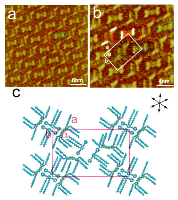
Deposition of a multi-component 20:1 (PBP:DTT) mixture on HOPG results in the coexistence of rectangular and rhombic hybrid nanopatterns with a molecular proportion of PBP:DTT = 1:1. (a) Large scale STM image. Itip = 390 pA, Vbias = 621 mV. (b) High-resolution STM image. Itip = 390 pA, Vbias = 621 mV. (c) Proposed structural model for the hybrid structure. A set of arrows indicates the orientation of the underlying HOPG lattice.
On the basis of above analysis, a structural model with a rectangular unit cell is proposed in Figure 7c. The model is consistent with the results in the STM images. The lattice constants of the unit cell are measured to be a = 7.7 ± 0.2 nm, b = 4.7 ± 0.2 nm, and α = 90 ± 2°. From the structural model, it is believed that the noncovalent van der Waals interactions between interdigitated alkyl chains of the PBP and DTT molecules in the rectangular and rhombic motifs are responsible for the overall pattern, packing, and stability of the adlayer. The increased concentration ratio of PBP to DTT results in greater competition between the excess PBP adsorbates and the stronger adsorbing DTT molecules. The ratio of PBP to DTT in the hybrid nanopattern is 1:1, reflecting an increase in the number of PBP molecules per unit cell relative to the ratio of 1:2 that was observed in Figure 6.
3.3.3. Pure rhombic hybrid nanopatterns
Further increasing the PBP:DTT concentration ratio to 30:1 results in the transformation of the mixed rectangular/rhombic adlayer assembly to a pure rhombic nanopattern. Figure 8a is a typical large scale STM image of the adlayer formed upon deposition of a 30:1 concentration ratio of PBP to DTT on an HOPG surface. Several molecular domains can be seen in the image with dashed lines indicating the boundaries between domains. The sizes of individual domains range from tens to several hundreds of nanometers. The STM image reveals that, with this increased ratio of PBP, a uniform rhombic motif is observed though each motif adopts a different orientation with respect to the HOPG surface in each domain. Figure 8b is a high-resolution STM image of the hybrid adlayer. The structural details of the molecular assembly, such as the arrangement of individual molecules and intermolecular interactions, can be seen in the high-resolution image. The molecular π-conjugated backbones of PBP and DTT are highlighted as red and white rods, respectively. The alkyl chains are aligned in a comb-like fashion between neighboring molecules. Four molecules form each rhombic motif. From the chemical structure and image features, two molecules in each rhomboid correspond to PBP while the other two molecules correspond to DTT. Careful observation of the high-resolution image reveals a significant difference between the rhombic structures of Figure 8 and those of the hybrid rectangle/rhomboid nanopattern shown in Figure 7. In the rhombic motifs shown in Figure 8, all six dodecyloxy chains of DTT align perpendicular to the dithienothiophene backbone whereas, in the rhombic motifs of Figure 7, four of the six dodecyloxy chains align perpendicular to the π-conjugated backbone while the other two align parallel to it. The differences between the molecular arrangements result in an overall different rhombic motif with different structural parameters. According to the periodicity of the rhombus motif, a unit cell for the multi-component nanopatterned assembly is deduced and superimposed in Figure 8b. The lattice constants of the unit cell are determined to be a = 5.8 ± 0.2 nm, b = 5.1 ± 0.2 nm, and α = 99 ± 2°. A structural model is proposed in Figure 8c. With the continued increase in the relative ratio of PBP to DTT during deposition, the ratio of PBP to DTT in the unit cell increases slightly to 5:4 in this hybrid nanopattern. This observation indicates that the significant change in the deposition concentration ratio of PBP to DTT (from 20:1 to 30:1) results in a much more subtle change in the ratio of PBP and DTT adsorbates (from 1:1 to 5:4). Moreover, the small change in the ratio of adsorbates is able to transform the structure of the adlayer nanopattern from a mixed rectangle/rhombic adlayer (Figure 7) to a pure rhombic nanopattern (Figure 8).
Figure 8.

Hybrid rhombic adlayer structure of PBP and DTT on HOPG at a deposition ratio of 30:1 (PBP:DTT). (a) Large scale STM image. Itip = 600 pA, Vbias = 600 mV. (b) High-resolution STM image. Itip = 258 pA, Vbias = 1050 mV. (c) Proposed structural model for the rhombic hybrid adlayer structure. A set of arrows indicates the orientation of the underlying HOPG lattice.
Closer examination of the structural details of the pure rhombic nanopattern shown in Figure 8 reveals an element of chirality in the nanopattern. Figures 9a and 9b are large-scale and high-resolution STM images of the adlayer, respectively, showing the chiral arrangement of the molecules. It can be seen from Figures 9a and 9b that the image consists of rhombic motifs. However, the rotational orientation of these rhombic structures is different between the neighboring molecular rows. As indicated in the image, alternating clockwise and anti-clockwise directions exist in the ordered molecular assembly, forming an element of local chirality. It is known that when achiral molecules adsorb on a solid surface, symmetry breaking can result in the formation of a chiral assembly due to substrate effects.44,45 In this case the HOPG substrate plays an important role in inducing symmetry breaking and enantiomorphic ordering of the hybrid architecture.
Figure 9.
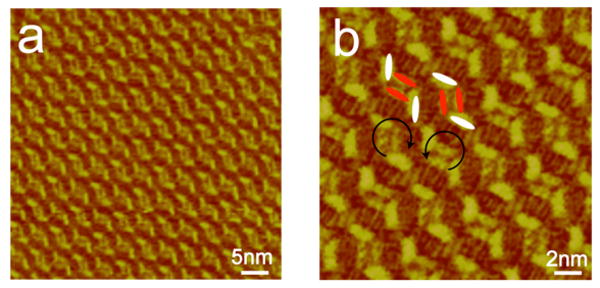
STM image showing a local chirality in the hybrid rhombic assembly. (a) Large-scale STM image. Itip = 600 pA, Vbias = 600 mV.(b) High-resolution STM image. Itip = 274 pA, Vbias = 314 mV.
3.3.4. Coexistence of an extended rhombic hybrid nanopatterns and a pure PBP assembly
When the PBP:DTT concentration ratio is increased to 100:1, extended rhombic hybrid nanopatterns as well as a pure PBP assembly are observed. Figure 10a is a typical, large-scale STM image of such an adlayer. Two ordered molecular domains can be seen and a dashed white line separates them. The adlayer structure in the two domains is different. From the structural features of the image, the domain in the lower left corner corresponds to that of a pure PBP adlayer, while the well-ordered adlayer in the upper right portion of the image consists of a coassembly of PBP and DTT adsorbates. Figure 10b is a high-resolution STM image of this coassembly. This structure is very similar to that shown in Figure 8, appearing to have a rhombic structural motif. However, intriguingly, the structural parameters and size of the rhombic motif in Figure 10b are different from that of the hybrid rhomboids in Figure 8. The length of both long sides of this new rhombus, 3.4 nm, is nearly double the length of the PBP backbone (1.74 nm, Figure 1). It is assumed that the long sides of each rhombus are composed of two PBP molecules while the shorter ends are composed of one DTT molecule each. The result is an extended rhombus. Moreover, careful observation reveals that the backbones of the two PBP adsorbates that make up the long sides of the rhombus shift along their molecular axis. This shift likely results in more favorable dipole-dipole interactions between the pyridyl moieties of neighboring PBP molecules, resulting in a more stable hybrid nanopatterned assembly. The details of the adlayer are made more explicit by the superimposition of molecular models on Figure 10b to illustrate their packing arrangement. Also shown beneath Figure 10b is the orientation of the underlying HOPG substrate. It is interesting to note that the dashed white line separating the two domains of Figure 10b lies parallel to the orientation of the substrate, suggestive of epitaxy with the HOPG surface. On the basis of the adlayer structure, a unit cell is deduced and a structural model for the adlayer is shown in Figure 10c. The lattice constants of the unit cell are estimated to be a = 8.7 ± 0.2 nm, b = 5.4 ± 0.2 nm and α = 95 ± 2°. Again, the increase in the relative ratio of PBP to DTT upon deposition results in an increase in the ratio of PBP adsorbates relative to DTT. In the hybrid nanopattern shown in Figure 10, the ratio of PBP to DTT in the unit cell is 2:1.
Figure 10.

Representative STM image of extended rhombic hybrid adlayer structure of PBP and DTT on HOPG (right side of the dashed line) as well as a section of a pure PBP adlayer (lower left) that form upon deposition of PBP and DTT on HOPG in a ratio of 100:1. (a) Large scale STM image. Itip = 600 pA, Vbias = 600 mV. (b) High-resolution STM image. Itip = 600 pA, Vbias = 600 mV. (c) Proposed structural model for the hybrid adlayer structure. A set of arrows indicates the orientation of the underlying HOPG lattice.
These results demonstrate that increasing the concentration ratio of PBP to DTT in the deposition solution results in a subsequent increase in relative ratio of PBP to DTT molecules adsorbed on the HOPG substrate. The structural transformation of hybrid nanopatterns that has been observed is summarized in Scheme 2.
Scheme 2.
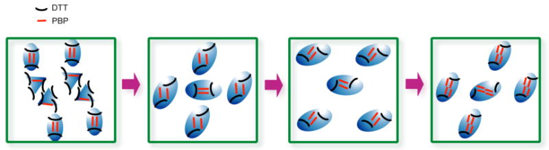
Schematic representation of the structural transformations that are observed in hybrid adlayers of PBP and DTT when the relative ratio of PBP adsorbates is increased from 2:1 to 100:1.
The present results demonstrate the control of hybrid adlayer nanopatterns on HOPG by varying the relative ratio of two different adsorbates. Generally, the formation of self-assembled monolayers on 2D surfaces is dependent on the subtle balance between adsorbate-adsorbate and substrate-adsorbate interactions.46-49 In a two-component system, however, the interactions involved are more diverse and more complex than that in a one-component system. The molecular conformation, chemical structure and concentration ratio of the two (or more) components each play important roles in the fabrication of a hybrid assembly. To achieve a patterned two-component nanostructure (i.e. an A-B system), suitable intermolecular interactions must exist between the two different molecules (A-B) and the strength of such interactions must be comparable to the intermolecular interactions that exist between the homogeneous molecules (A-A and B-B). Four possibilities can be considered in the formation of a two-component hybrid adlayer: (1) phase separation; (2) preferential adsorption; (3) hybrid assembly; and (4) random coadsorption.50 If the intermolecular interactions between homogeneous molecules (A-A or B-B) are larger than those of different molecules (A-B), a phase separation will occur. In other words, if weak intermolecular interaction exists between heterogeneous molecules, it is difficult to form a hybrid assembly. On the other hand, substrate-adsorbate interactions are another important factor that can affect the formation of a hybrid assembly.21,51 If one molecule in a binary system exhibits stronger interactions with the substrate then it will preferentially adsorb onto the substrate surface, resulting in a preferential adsorption. In the present experiment, when the relative ratio of PBP is lower than that of DTT, solution deposition results in preferential adsorption of only DTT. This observation marks the lower limit of forming a hybrid adlayer assembly in the current experiment. Adjusting the PBP:DTT concentration ratio gives rise to a series of well-ordered, though different, hybrid adlayer assemblies due to dipole-dipole and van der Waals interactions between PBP and DTT. This result suggests that by controlling concentration ratios, a molecule with a tendency toward preferential adsorption can also be employed to form hybrid adlayer assemblies. There exists, however, an upper limit to hybrid adlayer formation, which is the concentration ratio above which only pure adlayers of the weakly adsorbing molecule are formed. In the current experiments this scenario was observed at relative concentration ratios greater than 100:1 (PBP:DTT). Upon changing the concentration ratio, the balance of adsorbate-adsorbate and substrate-adsorbate interactions changes, resulting in the ability to control hybrid adlayer nanopatterns between the two extremes of preferential adsorption of one molecule or another.
3.4. STS measurements
3.4.1. STS of DTT and PBP
Recently, fused thiophene derivatives have been used in organic field-effect transistors and organic solar cells due to their highly-ordered π-stacked structures in the solid state and thin films and their high hole mobilities.52,53 The hybrid structure of fused thiophene donors with different acceptors may be useful for organic solar cell applications. Following the successful preparation of DTT and PBP adlayers, as well as their hybrid adlayer assemblies, the electronic properties of the adlayers were investigated by scanning tunneling spectroscopy (STS).
Figures 11 and 12 are dI/dV-V curves recorded for the self-assembled adlayers of DTT and PBP, respectively. The dI/dV-V curves reflect the density states of the adsorbates. When applying an appropriate bias on the substrate, the Fermi energy of the substrate will resonate with corresponding molecular orbitals of the adsorbate molecules, either the highest occupied molecular orbital (HOMO) or lowest unoccupied molecular orbital (LUMO), and induce a sharp change in dI/dV-V curve. HOMO and LUMO levels of the adsorbate molecules are estimated from the edges of these lines as defined by the cross-point of the tangents of the platform and uplift part of the curve. The energy gap between the HOMO and LUMO molecular orbitals corresponds to the separation between these two edges.
Figure 11.
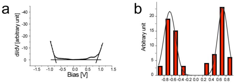
STS result for the DTT adlayer on HOPG. (a) dI/dV-V curve. (b) The histogram of experimental edges. The black solid line shows a Gaussian fit.
Figure 12.

STS result of the PBP adlayer on HOPG. (a) dI/dV-V curve. (b) The histogram of experimental edges. The black solid line shows a Gaussian fit.
The histograms in Figures 11 and 12 show the statistical distributions of HOMO and LUMO energies from a large number of STS spectra for DTT and PBP adlayers. The experimental energy gap distribution is given by a Gaussian fit of the histogram data. The statistical results reveal that the left (HOMO) and right (LUMO) edges for DTT are at -0.64 and 0.78 eV with a gap of 1.42 ± 0.2 eV, and those for PBP are at -0.72 and 0.62 eV with a gap of 1.34 ± 0.2 eV. Theoretical simulations (Material studio 3.1, DFT theory) show that both the HOMO and LUMO orbitals of DTT and of PBP are located on their respective π-conjugated backbones and oxygen atoms, and that the contribution of the dodecyl substituents can be neglected (Figure 1). The calculated HOMO-LUMO gaps are 1.66 eV for DTT and 1.42 eV for PBP. The STS experimental data are approximately consistent with theoretical simulations.
3.4.2. STS of a hybrid rhombic structure
STS was used to investigate the electronic properties of PBP and DTT molecules in a hybrid adlayer assembly. The HOMO and LUMO orbital energies were measured at PBP and DTT, respectively, to investigate the effects the hybrid adlayer structure has on the electronic properties of the two molecular adsorbates.
Figure 13 displays the dI/dV-V results recorded from the rhombic hybrid assembly shown in Figure 8. The curves for PBP and DTT are presented as red and black dotted lines, respectively. Statistical results reveal that the left and right edges for DTT are at -0.71 and 0.68 eV with a gap of 1.39 ± 0.2 eV, and that for PBP are at -0.63 and 0.68 eV with a gap of 1.31 ± 0.2 eV. The results are almost same as those in Figures 11 and 12 for individual PBP and DTT assemblies, indicating that the energy levels of PBP and DTT are relatively insensitive to changes in the hybrid supramolecular architecture. These results are reasonable given that there are no strong intermolecular interactions between PBP and DTT. In measuring the molecules in the hybrid architecture, it is possible that thermal drifting may affect the accuracy of positioning the exact site of PBP or DTT adsorbates. However, the STS results in Figure 13 show a stable conductance for both of the two molecules in the hybrid architecture, which is necessary for efficient organic semiconductor performance in device applications.
Figure 13.

STS results recorded from the rhombic hybrid structure formed upon deposition of a 100:1 ratio of PBP and DTT on HOPG. (a) dI/dV-V curves obtained for DTT and PBP. (b) The histogram of experimental edges of DTT. (c) The histogram of experimental edges of PBP.
4. Conclusions
Nanopatterned hybrid adlayer architectures composed of 1,4-bis(4-pyridylethynyl) -2,3-bis-dodecyloxy-benzene (PBP) and 2,6-bis(3,4,5-tris-dodecyloxy-phenyl) dithieno[3,2-b:2′,3′-d]thiophene (DTT) have been successfully fabricated on an HOPG surface and have been thoroughly investigated by STM and STS. The hybrid structures are highly dependent on the molar ratio of PBP to DTT. Carefully adjusting this molar ratio allows for a variety of hybrid nanopatterns with rectangular, rhombic, and extended rhombic motifs to be formed in a controllable manner. The increase in the molar ratio of PBP to DTT results in a corresponding, though less dramatic, increase in the ratio of PBP to DTT in the unit cell of each ordered adlayer. Intermolecular adsorbate-adsorbate interactions in the hybrid structures play the dominant role in the formation of hybrid adlayer structures. The coexistence of two molecules has the effect of modulating and changing the environment surrounding each adsorbate and, thus, inter-adsorbate intermolecular interactions. Although DTT is preferentially inclined to adsord on an HOPG surface, the addition of different relative amounts of PBP changes the molecular environment and results in different well-ordered hybrid adlayer architectures. An interesting element of surface chirality is observed in one of the hybrid adlayer assemblies in which the HOPG substrate induces a symmetry breaking of the hybrid assembly and produces locally chiral arrangements from achiral molecules. The results presented here are of significance to an understanding of how the fabrication of hybrid adlayer nanopatterns can be controlled on 2D surfaces and to the further development of multicomponent organic materials.
Supplementary Material
Experimental procedure for the synthesis of DTT as well as STM corrugation height measurements and composite STM images demonstrating monolayer formation and revealing the orientation between adlayers and HOPG. This material is available free of charge via the Internet at http://pubs.acs.org.
Acknowledgments
This work was supported by the National Natural Science Foundation of China (Nos. 20575070, 20673121, and 20733004), National Key Project on Basic Research (Grant Nos. 2006CB806100 and 2006CB932100), and the Chinese Academy of Sciences. P.J.S. thanks the NSF (CHE-0306720 and CHE-0820955) for support. B.H.N. thanks the NIH (Grant GM-080820) for support.
References
- 1.Barth JV, Costantini G, Kern K. Nature. 2005;437:671. doi: 10.1038/nature04166. [DOI] [PubMed] [Google Scholar]
- 2.Cheng JY, Mayes AM, Ross CA. Nat Mater. 2004;3:823. doi: 10.1038/nmat1211. [DOI] [PubMed] [Google Scholar]
- 3.Joachim C, Gimzewski JK, Aviram A. Nature. 2000;408:541. doi: 10.1038/35046000. [DOI] [PubMed] [Google Scholar]
- 4.Winfree E, Liu FR, Wenzler LA, Seeman NC. Nature. 1998;394:539. doi: 10.1038/28998. [DOI] [PubMed] [Google Scholar]
- 5.Gimzewski JK, Joachim C. Science. 1999;283:1683. doi: 10.1126/science.283.5408.1683. [DOI] [PubMed] [Google Scholar]
- 6.Yan H, Park SH, Finkelstein G, Reif JH, LaBean TH. Science. 2003;301:1882. doi: 10.1126/science.1089389. [DOI] [PubMed] [Google Scholar]
- 7.Wang YY, Kioupakis E, Lu XH, Wegner D, Yamachika R, Dahl JE, Carlson RMK, Louie SG, Crommie MF. Nat Mater. 2008;7:38. doi: 10.1038/nmat2066. [DOI] [PubMed] [Google Scholar]
- 8.Fritz J, Baller MK, Lang HP, Rothuizen H, Vettiger P, Meyer E, Guntherodt HJ, Gerber C, Gimzewski JK. Science. 2000;288:316. doi: 10.1126/science.288.5464.316. [DOI] [PubMed] [Google Scholar]
- 9.Donhauser ZJ, Mantooth BA, Kelly KF, Bumm LA, Monnell JD, Stapleton JJ, Price DW, Rawlett AM, Allara DL, Tour JM, Weiss PS. Science. 2001;292:2303. doi: 10.1126/science.1060294. [DOI] [PubMed] [Google Scholar]
- 10.Lopinski GP, Wayner DDM, Wolkow RA. Nature. 2000;406:48. doi: 10.1038/35017519. [DOI] [PubMed] [Google Scholar]
- 11.Puigmarti-Luis J, Minoia A, Uji-i H, Rovira C, Cornil J, De Feyter S, Lazzaroni R, Amabilino DB. J Am Chem Soc. 2006;128:12602. doi: 10.1021/ja0640288. [DOI] [PubMed] [Google Scholar]
- 12.(a) Wan LJ. Acc Chem Res. 2006;39:334. doi: 10.1021/ar0501929. [DOI] [PubMed] [Google Scholar]; (b) Wang D, Wan LJ. J Phys Chem C. 2007;111:16109–16130. [Google Scholar]
- 13.Kampschulte L, Lackinger M, Maier AK, Kishore RSK, Griessl S, Schmittel M, Heckl WM. J Phys Chem B. 2006;110:10829. doi: 10.1021/jp057553m. [DOI] [PubMed] [Google Scholar]
- 14.Klymchenko AS, Furukawa S, Mullen K, Van der Auweraer M, De Feyter S. Nano Lett. 2007;7:791. doi: 10.1021/nl0700752. [DOI] [PubMed] [Google Scholar]
- 15.Qiu DL, Ye KQ, Wang Y, Zou B, Zhang X. Langmuir. 2003;19:678. [Google Scholar]
- 16.Yoshimoto S, Suto K, Tada A, Kobayashi N, Itaya K. J Am Chem Soc. 2004;126:8020. doi: 10.1021/ja048760n. [DOI] [PubMed] [Google Scholar]
- 17.Gopakumar TG, Muller F, Hietschold M. J Phys Chem B. 2006;110:6051. doi: 10.1021/jp055533e. [DOI] [PubMed] [Google Scholar]
- 18.De Feyter S, De Schryver FC. J Phys Chem B. 2005;109:4290. doi: 10.1021/jp045298k. [DOI] [PubMed] [Google Scholar]
- 19.Mamdouh W, Uji-i H, Ladislaw JS, Dulcey AE, Percec V, De Schryver FC, De Feyter S. J Am Chem Soc. 2006;128:317. doi: 10.1021/ja056175w. [DOI] [PubMed] [Google Scholar]
- 20.Rohde D, Yan CJ, Yan HJ, Wan LJ. Angew Chem Int Ed. 2006;45:3996. doi: 10.1002/anie.200600725. [DOI] [PubMed] [Google Scholar]
- 21.Hooks DE, Fritz T, Ward MD. Adv Mater. 2001;13:227. [Google Scholar]
- 22.Peumans P, Uchida S, Forrest SR. Nature. 2003;425:158. doi: 10.1038/nature01949. [DOI] [PubMed] [Google Scholar]
- 23.Petritsch K, Dittmer JJ, Marseglia EA, Friend RH, Lux A, Rozenberg GG, Moratti SC, Holmes AB. Sol Energy Mater Sol Cells. 2000;61:63. [Google Scholar]
- 24.Wohrle D, Meissner D. Adv Mater. 1991;3:129. [Google Scholar]
- 25.Peumans P, Forrest SR. Appl Phys Lett. 2001;79:126. [Google Scholar]
- 26.Peumans P, Yakimov A, Forrest SR. J Appl Phys. 2003;93:3693. [Google Scholar]
- 27.Xue JG, Rand BP, Uchida S, Forrest SR. Adv Mater. 2005;17:66. [Google Scholar]
- 28.Plass KE, Engle KM, Cychosz KA, Matzger AJ. Nano Lett. 2006;6:1178. doi: 10.1021/nl0605061. [DOI] [PubMed] [Google Scholar]
- 29.Hipps KW, Scudiero L, Barlow DE, Cooke MP. J Am Chem Soc. 2002;124:2126. doi: 10.1021/ja017561q. [DOI] [PubMed] [Google Scholar]
- 30.Canas-Ventura ME, Xiao W, Wasserfallen D, Mullen K, Brune H, Barth JV, Fasel R. Angew Chem Int Ed. 2007;46:1814. doi: 10.1002/anie.200604083. [DOI] [PubMed] [Google Scholar]
- 31.Tao F, Bernasek SL. J Am Chem Soc. 2005;127:12750. doi: 10.1021/ja050365p. [DOI] [PubMed] [Google Scholar]
- 32.While the dodecyloxy chains and pyridyl moieties do impart some amount of electron rich character to PBP, the ethynyl groups render the compound an acceptor relative to DTT.
- 33.Northrop BH, Glockner A, Stang PJ. J Org Chem. 2008;73:1787. doi: 10.1021/jo702380b. [DOI] [PubMed] [Google Scholar]
- 34.Wu J, Watson MD, Zhang L, Wang Z, Mullen K. J Am Chem Soc. 2004;126:177. doi: 10.1021/ja037519q. [DOI] [PubMed] [Google Scholar]
- 35.Zhan X, Tan Z, Domercq B, An Z, Zhang X, Barlow S, Li Y, Zhu D, Kippelen B, Marder SR. J Am Chem Soc. 2007;129:7246. doi: 10.1021/ja071760d. [DOI] [PubMed] [Google Scholar]
- 36.Chen Q, Yan HJ, Yan CJ, Pan GB, Wan LJ, Wen GY, Zhang DQ. Surf Sci. 2008;602:1256. [Google Scholar]
- 37.Yin SX, Wang C, Qiu XH, Xu B, Bai CL. Surf Interface Anal. 2001;32:248. [Google Scholar]
- 38.Qiu XH, Wang C, Yin SX, Zeng QD, Xu B, Bai CL. J Phys Chem B. 2000;104:3570. [Google Scholar]
- 39.(a) Yau SL, Kim YG, Itaya K. J Phys Chem B. 1997;101:3547. [Google Scholar]; (b) Diao YX, Han MJ, Wan LJ, Itaya K, Uchida T, Miyake H, Yamakata A, Osawa M. Langmuir. 2006;22:3640. doi: 10.1021/la052765w. [DOI] [PubMed] [Google Scholar]
- 39.Yang R, Smyrl WH, Evans DF, Hendrickson WA. J Phys Chem B. 1992;96:1428. [Google Scholar]
- 40.Avouris P. Acc Chem Res. 1994;27:159. doi: 10.1021/ar010152e. [DOI] [PubMed] [Google Scholar]
- 41.Watson MD, Jackel F, Severin N, Rabe JP, Mullen K. J Am Chem Soc. 2004;126:1402. doi: 10.1021/ja037520p. [DOI] [PubMed] [Google Scholar]
- 42.Kim K, Plass KE, Matzger AJ. Langmuir. 2003;19:7149. [Google Scholar]
- 43.Vidal F, Delvigne E, Stepanow S, Lin N, Barth JV, Kern K. J Am Chem Soc. 2005;127:10101. doi: 10.1021/ja0525049. [DOI] [PubMed] [Google Scholar]
- 44.Shao X, Luo XC, Hu XQ, Wu K. J Phys Chem B. 2006;110:15393. doi: 10.1021/jp060811a. [DOI] [PubMed] [Google Scholar]
- 45.Hoster HE, Roos M, Breitruck A, Meier C, Tonigold K, Waldmann T, Ziener U, Lantifester K, Behm RJ. Langmuir. 2007;23:11570. doi: 10.1021/la701382n. [DOI] [PubMed] [Google Scholar]
- 46.Otsuki J, Nagamine E, Kondo T, Iwasaki K, Asakawa M, Miyake K. J Am Chem Soc. 2005;127:10400. doi: 10.1021/ja0531778. [DOI] [PubMed] [Google Scholar]
- 47.Mannsfeld SCB, Fritz T. Phys Rev B. 2004;69:5416. [Google Scholar]
- 48.Guaino P, Cafolla AA, Carty D, Sheerin G, Hughes G. Surf Sci. 2003;540:107. [Google Scholar]
- 49.Yuan QH, Wan LJ, Jude H, Stang PJ. J Am Chem Soc. 2005;127:16279. doi: 10.1021/ja0549300. [DOI] [PubMed] [Google Scholar]
- 50.(a) Schott JH, Yip CM, Ward MD. Langmuir. 1995;11:177. [Google Scholar]; (g) Gong JR, Wan LJ, Yuan QH, Bai CL, Jude H, Stang PJ. Proc Natl Acad Sci USA. 2005;102:971. doi: 10.1073/pnas.0409145102. [DOI] [PMC free article] [PubMed] [Google Scholar]
- 51.Xiao K, Liu YQ, Qi T, Zhang W, Wang F, Gao JH, Qiu WF, Ma YQ, Cui GL, Chen SY, Zhan XW, Yu G, Qin JG, Hu WP, Zhu DB. J Am Chem Soc. 2005;127:13281. doi: 10.1021/ja052816b. [DOI] [PubMed] [Google Scholar]
- 52.Muhlbacher D, Scharber M, Morana M, Zhu ZG, Waller D, Gaudiana R, Brabec C. Adv Mater. 2006;18:2884. [Google Scholar]
Associated Data
This section collects any data citations, data availability statements, or supplementary materials included in this article.
Supplementary Materials
Experimental procedure for the synthesis of DTT as well as STM corrugation height measurements and composite STM images demonstrating monolayer formation and revealing the orientation between adlayers and HOPG. This material is available free of charge via the Internet at http://pubs.acs.org.