Abstract
The synthesis of new benzo[a]- and [b]xanthene dye frameworks is described. A unique benzo-[a]xanthene, seminaphtho[a]fluorone (SNAFR-1), is studied in a variety of media. The optimization of solution parameters and excitation wavelengths allows SNAFR-1 to display red, green, and blue emission bands of approximately equal intensities and also to produce white light. Ratiometric red (anion) and green (neutral) emissions are observed upon varying solution pH. A pH-independent violet-blue emission band is due to the addition of nucleophiles to the benzylic carbon of SNAFR-1.
Introduction
Terenin et al. reported the first example of dual fluorescence resulting from an intermolecular excited-state proton transfer (ESPT) in 1947.1a In 1950, Forster’s first paper on ESPT was published.1b Since then, several compounds, such as 4-(N,N-dimethylamino)-benzonitrile (DMABN) and its analogues,2 biaryls,3 benzo[c]xanthenes,4 3-hydroxyflavones,5 hydroxy-camptothecin,6 6-hydroxyquinoline-N-oxides,7 aromatic dicar-boximides,8 carotenoids,9 1,3-diphenyl-1H-pyrazolo[3,4-b]-quinoline,10 etc., have been reported to display dual signaling excitation and emission properties based on intermolecular or intramolecular ESPT,11 twisted intramolecular charge transfer (TICT),12 tautomerization,4 and other mechanisms.13
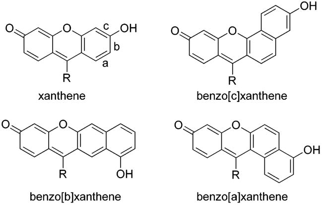
Dual ratiometric fluorescence signaling reduces errors due to photobleaching, uneven loading of probes and/or fluctuations in excitation intensity.14 Ratiometric probes have been shown to be useful for intracellular pH,15 viscosity,13a,16 and Ca2+ measurement.17 Additionally, they are important in applications such as flow cytometry, confocal microscopy, emission ratio imaging, as well as many others.4a,18 Benzo[c]xanthenes (Figure 1) are of interest as dual fluorescence ratiometric indicators because of (i) their well-resolved emission bands, (ii) relatively long wavelength absorptions and emissions, (iii) near neutral pKa values, and (iv) clear isosbestic and isoemissive points.4a,19
Figure 1.
The xanthene dye framework and the three types of benzoxanthenes. Benzoxanthene types are each distinguished via the orientation of their naphthyl moieties.
The regioisomers of benzo[c]xanthene, namely benzo[a]xanthene and benzo[b]xanthene, were essentially overlooked until Wolfbeis et al. investigated their properties using semiempirical molecular orbital calculations. They were predicted to absorb and emit at longer wavelengths compared to their type [c] analogues. Apparently because of prior limitations in xanthene synthesis methodology, they had not been prepared to date.19
We have recently reported a novel synthesis of xanthene dyes.20 It involves the initial formation of methylated carbinol intermediates, followed by demethylation and concomitant condensation (Scheme 1). Current studies embody an extension of this prior work to access novel benzannulated derivatives.
Scheme 1.
A Simple and Efficient Synthesis of Xanthene Dyes
Herein, we report the synthesis of type [a] and [b] benzoxanthenes. Importantly, we find that a new seminaphtho[a]-fluorone (SNAFR-1) can display three emission maxima of approximately equal intensities, in the blue, green, and red spectral regions, respectively. When excited at ca. 300 nm, it emits near white light, which resembles the white light from an incandescent light bulb. White light is to date highly sought-after owing to potential applications in (i) light emitting diodes (LEDs),21 replacements for current illumination devices such as incandescent bulbs and fluorescent lamps, (ii) flat panel displays (FPDs),22 as the next generation display devices after liquid crystal displays (LCDs), and (iii) electronic paper displays (E-PADs),23 as an electronic analogue of paper, etc. Traditional methods of molecular white light generation typically involve mixing different primary colors from different emitting materials, such as red, green, and blue fluorophores.24 Alternative and single component recent examples include (i) white light photoluminescence from nanocrystals,25 (ii) electroluminescence from a fullerene adduct,26 (iii) electroluminescence from a π-conjugated aromatic enyne,27 (iv) electroluminescence from platinum-functionalized random copolymer,28 and (v) photoluminescence from microporous metal phosphates and silicates.29
Fluorophores with tunable emissive properties are of current interest for multiplexing applications. In addition to serving as a simple white light-emitting fluorophore, SNAFR-1 can be excited anywhere within the UV to the deep red spectral regions. It exhibits a unique emission spectrum corresponding to each excitation wavelength. SNAFR-1 is pH sensitive, soluble in cell culture media, stains cells, and exhibits no cytotoxicity in studies carried out to date.
Results and Discussion
Benzo[a]- and [b]xanthene Dyes Synthesis
Xanthene dyes are typically synthesized via the acid-catalyzed condensation between resorcinol and various analytes, for example, phthalic anhydride, acid chloride, ester, or aldehyde.30 Upon replacing resorcinol with 1,6-dihyxdroxynaphthalene, under classical acid-catalyzed thermal conditions, known benzo[c]xanthene is formed.
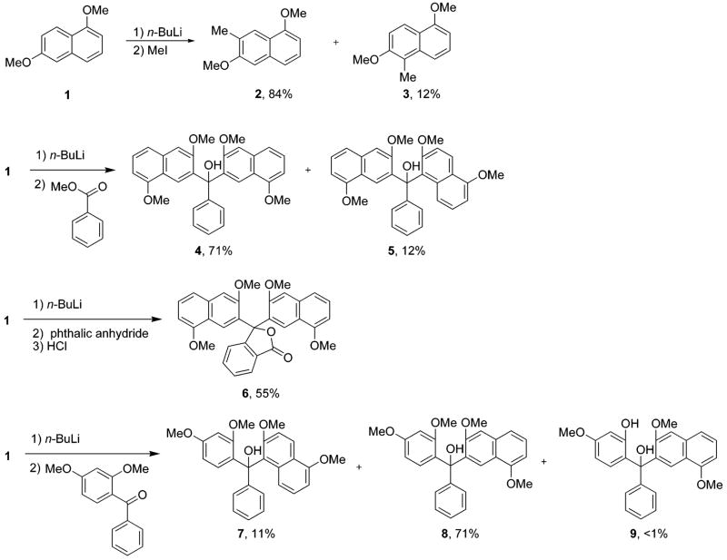
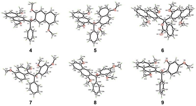
It has been shown by others that when 1,6-dimethoxynaphthalene (1) is treated with n-BuLi and quenched with MeI, 2 and 3 are obtained in yields of 84% and 12%, respectively.31 When a solution of lithiated 1 is treated with methyl benzoate, we obtain 4 and 5 in isolated yields of 71% and 12%, respectively. When phthalic anhydride is used instead of methylbenzoate, 6 is obtained in 55% yield. Upon treating lithiated 1,6-dimethoxynaphthalene with 2,4-dimethoxyben-zophenone, 7 and 8 are isolated in 11% and 71% yields, respectively (Scheme 2). Additionally, trace amounts of 9 are obtained. This is presumably because of trace amounts of 2-hydroxy-4-methoxybenzophenone in the reaction mixture from incomplete methylation of 2,4-dihydroxybenzophenone. Single-crystal X-ray structure analysis confirms the assigned structures of 4–9 (Figure 2).
Scheme 2.
Synthesis of Precursors of Type [a]- and [b]Benzoxanthenes
Figure 2.
Ortep drawings and numbering schemes of compounds 4–9.
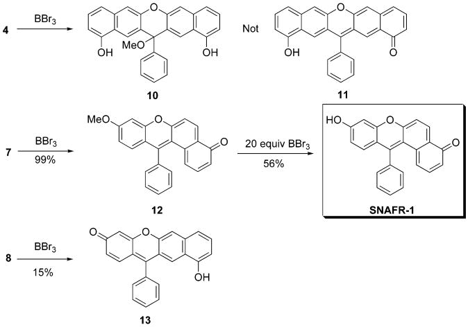
When BBr3 is used to demethylate 4, compound 10 is obtained in 61% yield. When 7 is demethylated, 12 is obtained quantitatively. Treatment of 12 using 20 more equiv of BBr3 affords 13 in 56% yield. When 8 is demethylated, 14 is obtained in a yield of 15% (Scheme 3). Structure assignments of 10 and 13 are confirmed by single-crystal X-ray structural analysis (Figure 3).
Scheme 3.
Synthesis of Type [a]- and [b]Benzoxanthenes
Figure 3.
Ortep drawings and numbering schemes of compounds 10 (with two acetone molecules) and 13.
UV–Visible Absorption Properties of SNAFR-1 as a Function of pH in 99.75% Buffer Solution
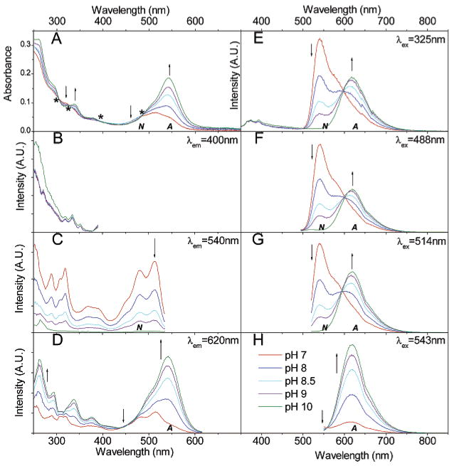
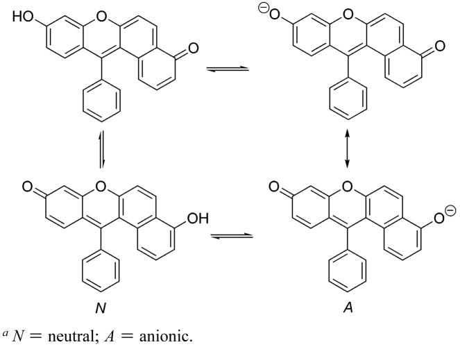
Absorption spectra of SNAFR-1 as a function of varying pH are shown (Figure 4A). SNAFR-1 is dissolved in 50 mM phosphate buffer with 0.25% DMSO. As the pH increases, the absorption band centered at 550 nm increases. This band is assigned to the anionic form (A, Scheme 4). At the same time, the absorption at ca. 460 nm decreases. The 460 nm band is assigned to the neutral form (N). Four isosbestic points at 484, 394, 327, and 304 nm are observed. The 484 nm isosbestic point is near the 488 nm Ar ion laser line. These latter results show that ratiometric experiments using SNAFR-1 as a probe may be performed with common, commercially available filter sets (vide infra).
Figure 4.
Spectral properties of 30 μM SNAFR-1 in 50 mM phosphate buffer at various pH values with 0.25% DMSO. The trend of spectral changes is indicated by arrows as the pH increases from 7 to 10. A = anionic form; N = neutral form. (A) Absorption spectra is shown; the * indicates the position of isosbestic points. (B–D) Excitation spectra is shown with emission monitored at 400, 540, and 620 nm, respectively. (E–H) Emission spectra excited at 325, 488, 514, and 543 nm, respectively, corresponding to common laser lines is shown. The legends for panels A–H are shown in panel H. All fluorescence spectra are normalized to the maximum of each data set.
Scheme 4.
Acid–Base Equilibria of SNAFR-1a
aN = neutral; A = anionic.
Fluorescence Properties of SNAFR-1 as a Function of pH in 99.75% Buffer Solution
Benzoxanthenes are known to afford dual emission bands whose intensities are pH dependent. SNAFR-1 thus also exhibits dual emission bands that are pH-sensitive. Upon increasing the solution pH, the intensity of the red emission band (620 nm), corresponding to the anionic form (A) increases, while that of the green emission band (540 nm), assigned to the neutral (N) form decreases (Figure 4E–H). The two emission bands are well-separated and show clear isoemissive points at ca. 600 nm when excited at 325, 488, and 514 nm (Figure 4E–G). When excited at 543 nm, only the tail of the emission from the neutral form plus the emission of the anion is observed, and a clear isoemissive point is present at 560 nm (Figure 4H). Excitation at longer wavelengths would further reduce the emission from the neutral form and eventually lead to red emission from the anion only with no isoemissive point. Most organic fluorophores are limited by their narrow excitation which hinders their use in multiplexing with other fluorophores. The absorption and excitation spectra of SNAFR-1 demonstrate that it can be excited from 260 nm up to 600 nm in buffer including various common laser lines, for example, HeCd at 325 nm, Ar ion at 488 and 514 nm, and HeNe at 543 nm (Figure 4A–D). This is further evidence that SNAFR-1 would be compatible with commercially available filter sets used in various spectroscopic instruments and fluorescence microscopes (vide infra). The pKa values for SNAFR-1 based on absorption and emission data are summarized in Table 1a. The pKa values calculated based on emission spectra using different excitation wavelengths vary from 8.31 to 8.38 with an average pKa–em of 8.34 ± 0.02. The pKa values calculated from absorption spectra based on different isosbestic points vary from 8.47 to 8.68, with an average pKa–abs of 8.53 ± 0.06. The mismatch of the pKa–abs values and pKa–em values suggests the presence of excited-state proton transfer (ESPT). Upon excitation, the acidity of SNAFR-1 increases, as measured in phosphate buffer containing 0.25% DMSO. The values for SNAFR-1 estimated using the Forster equation are summarized in Table 1b. When different methods were applied to calculate the optical frequency of the light needed to excite the molecule from its ground state to its lowest excited state, the value was found to vary from 3.3 to 6.3. It is interesting to note that when the 0–0 excitation method is used, ν̃anion − ν̃neutral of 1813 cm− 1 is obtained, which is in close agreement with 1700 cm− 1 calculated for C.SNAFL-1.4a The is calculated to be 4.54 or 4.73 at room temperature, when pKa–em and pKa–abs are used, respectively. These results demonstrate that the acidity of SNAFR-1 increases in the excited state.
Table 1.
| Table 1a. The pKa Values for SNAFR-1 Based on Absorption and Emission Dataa | |||||||
|---|---|---|---|---|---|---|---|
| method | λex | λisosbestic | λ1/λ2 | Rmax | Rmin | pKa | |
| em | 325 | 627/597 | 1.33 | 0.54 | 8.38 | ||
| em | 325 | 575/597 | 1.42 | 0.35 | 8.32 | ||
| em | 325 | 541/597 | 2.31 | 0.06 | 8.32 | ||
| em | 488 | 630/600 | 1.16 | 0.51 | 8.35 | ||
| em | 488 | 575/600 | 1.47 | 0.32 | 8.36 | ||
| em | 488 | 542/600 | 2.47 | 0.05 | 8.33 | ||
| em | 514 | 623/595 | 1.44 | 0.57 | 8.34 | ||
| em | 514 | 575/595 | 1.33 | 0.36 | 8.32 | ||
| em | 514 | 539/595 | 2.16 | 0.02 | 8.31 | ||
| abs | 484 | 543/484 | 3.76 | 0.88 | 8.52 | ||
| abs | 484 | 511/484 | 2.04 | 1.23 | 8.54 | ||
| abs | 484 | 469/484 | 0.48 | 0.37 | 8.47 | ||
| abs | 394 | 380/394 | 1.41 | 1.14 | 8.68 | ||
| abs | 394 | 344/394 | 2.73 | 1.90 | 8.58 | ||
| abs | 327 | 380/327 | 0.52 | 0.40 | 8.51 | ||
| abs | 327 | 344/327 | 0.99 | 0.67 | 8.51 | ||
| abs | 327 | 312/327 | 1.17 | 0.99 | 8.54 | ||
| abs | 304 | 312/304 | 0.91 | 0.75 | 8.48 | ||
| abs | 304 | 296/304 | 1.38 | 1.13 | 8.54 | ||
| abs | 304 | 265/304 | 2.79 | 2.07 | 8.48 | ||
|
| |||||||
| Table 1b. The
Values for SNAFR-1 Estimated Using the Forster Equationa | |||||||||
|---|---|---|---|---|---|---|---|---|---|
| neutral form |
anionic form |
||||||||
| methods | ν̃neutral | λneutral | ν̃anion | λanion | ν̃anion − ν̃neutral | ||||
| absorption | 19 495 | 512.94 | 18 451 | 541.99 | 1045 | 6.15 | 6.34 | ||
| excitation | 19 608 | 510.00 | 18 519 | 540.00 | 1089 | 6.05 | 6.25 | ||
| emission | 18 484 | 541.00 | 16 103 | 621.00 | 2381 | 3.34 | 3.54 | ||
| 0–0 absorption | 18 789 | 532.23 | 17 248 | 579.77 | 1541 | 5.11 | 5.30 | ||
| 0–0 excitation | 19 084 | 524.00 | 17 271 | 579.00 | 1813 | 4.54 | 4.73 | ||
|
| |||||||||
The pKa of SNAFR-1 in 50 mM phosphate buffer containing 0.25% DMSO was determined using the above equation.4a The pKa is taken to be the intercept of the plot of pH versus the first log term in the equation, where c is the slope; R is the ratio from the spectral data at λ1 and λ2; Rmax and Rmin are the limiting values of this ratio; and Ia/Ib is the ratio of the spectral intensity in acid to that in base at the wavelength chosen for the denominator of R. This last term may be neglected by choosing an isosbestic or isoemissive point as the denominator of R.
The of SNAFR-1 in 50 mM phosphate buffer containing 0.25% DMSO was determined using the above equation11e with ν̃anion − ν̃neutral determined from various methods. is the pKa at the first electronically Ka excited state (S1). NA is the Avogadro’s number. The h is the Plank’s constant. The c is the light speed in the unit of cm/s. The ν̃ anion and ν̃neutral (cm− 1) are the optical frequencies of the 0–0 transition in the neutral and anionic form, respectively. The R is the ideal gas constant. The T (K) is the temperature where absorption and fluorescence spectra were collected. The λ (nm) is the wavelength. The is the pKa of S1 state calculated using pKa–em = 8.34. The is the pKa of S1 state calculated using pKa–abs = 8.53. The 0–0 absorption/excitation is the intersection of the emission with absorption/excitation spectra of neutral or anionic form, respectively.
SNAFR-1 Is a Single Component Red–Green–Blue (RGB) Fluorophore
Importantly, a third emission band is present at 390 nm when SNAFR-1 is excited in the UV region (Figure 4B,E). Thus, SNAFR-1 emits in the violet–blue (λem = 390 nm), green (λem = 540 nm), and red (λem = 620 nm) spectral regions. The violet–blue emission is of relatively low intensity compared to the emission from the neutral and anionic forms. However, the intensity of the blue emission is increased in organic solvents (vide infra).
Spectral Properties of SNAFR-1 in Organic Solvents
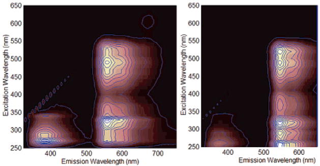
SNAFR-1 is fluorescent in organic solvents such as MeOH and DMSO. It exhibits dual emission with two emission bands located at 390 and 560 nm in DMSO and blue shifted to 385 and 550 nm in MeOH. Excitation–emission matrixes (EEMs) of SNAFR-1 in MeOH and DMSO are shown in Figure 5. Spectral properties of SNAFR-1 in DMSO and MeOH are summarized in Table 2. Violet-blue emission is observed to increase in these organic solvents compared to buffer. The green emission is attributed to the neutral form. As expected, the emission corresponding to the anionic form is diminished in both solvents.
Figure 5.
Excitation–emission matrixes (EEM) of 30 μM SNAFR-1 in DMSO (left) an d MeOH (right).
Table 2.
A Summary of Spectral Properties of SNAFR-1 in DMSO and MeOH
| DMSO | MeOH | |
|---|---|---|
| λabsa (nm) | 493, 528 | 489, 523 |
| εb (M− 1 cm− 1) | 7500, 6000 | 11800, 13200 |
| λemc (nm) | 390, 560 | 385, 550 |
| λemd (nm) | 560 | 550 |
| Φe | 0.33 | 0.41 |
λabs are peak locations in the absorbance spectra.
ε is the molar extinction coefficient corresponding to each λabs.
λem are the peak locations in the emission spectra when excited at 325 nm.
λem are peak locations in the emission spectra when excited at 488 and 514 nm.
Quantum yields of compound SNAFR-1 relative to rhodamine 6G in EtOH (Φ = 1). The excitation wavelength was 514 nm for both SNAFR-1 and rhodamine 6G.
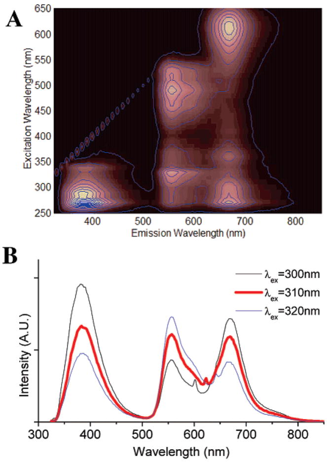
When phosphate buffer32 (0.25% final volume) is added to the DMSO solution of SNAFR-1, deep red emission attributed to the anionic form appears with a corresponding decrease in green emission attributed to the neutral form. Most interestingly, three emissions of nearly equal intensity in the violet–blue, green, and red spectral region appear when excited in the UV region, when ca. neutral buffer solutions are added (Figure 6). As a result, the emission is nearly white. SNAFR-1 can be excited over a 400 nm spectral window anywhere from ca. 260 to 660 nm with corresponding emissions ranging from violet, white, yellow, green to deep red.
Figure 6.
(A) Excitation emission matrix for 30 μM SNAFR-1 in DMSO with 0.25% phosphate buffer (50 mM, pH 7). (B) When excited at 310 nm, SNAFR-1 shows violet–blue, green, and red emission of approximately equal intensities.
Spectral Properties of SNAFR-1 in DMSO
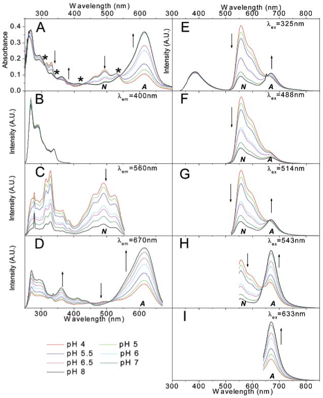
The absorption and fluorescence spectra as a function of phosphate buffer pH added to DMSO are shown in Figure 7. When the pH of the added buffer is low, the absorption from both the neutral and anionic forms is distinct. Above pH = 6, absorption from the anion dominates. Four clear isosbestic points are observed at 311, 345, 427, and 538 nm (Figure 7A). Emission spectra excited at or below the 538 nm isosbestic point show that the green emission at 560 nm from the neutral form decreases as the pH of the phosphate buffer increases. The opposite trend is observed for the emission at 670 nm, assigned to the anionic form of SNAFR-1 (Figure 7E–I). Figure 7I shows that excitation at 633 nm, much longer than the 538 nm isosbestic point, excites only the anion yielding only the emission at 670 nm with no isoemissive point. A clear isoemissive point is likely not apparent in Figure 7F because excitation at 488 nm results in only minimal emission from the anion. Under these conditions, emission from the neutral form dominates at all pH values investigated. The best ratiometric behavior would occur when excitation is at 538 nm (an isosbestic point), similar to the 543 nm output of a green HeNe laser (Figure 7H).
Figure 7.
Spectral properties of 30 μM SNAFR-1 in DMSO with 0.25% phosphate buffer (50 mM) at various pH values. The trend of spectral changes is indicated by arrows as the pH increases from 4 to 8. A = anionic form; N = neutral form. (A) Absorption spectra is shown; the * in panel A indicates the positions of isosbestic points in absorbance spectra. (B–D) Excitation spectra with emission monitored at 400, 560, and 670 nm, respectively, is shown. (E–I) Data are emission spectra excited at 325, 488, 514, 543, and 633 nm, respectively, corresponding to common laser lines. All fluorescence spectra are normalized to the maximum of each data set.
Compared to the red and green emissions, the violet–blue emission does not show a strong dependence on the added buffer pH (Figure 7E). Fluorescence excitation spectra, monitored at p400 nm, also verify that the violet–blue emission is independent of pH (Figure 7B).
Lower pH results in greater excitation intensity at 490 nm when monitored at the 560 nm peak of green emission band (Figure 7C). This is explained by the increased formation of the neutral form at low pH. At the same time, the opposite trend is observed at 610 nm for the excitation spectra of the anion form monitored at the peak of the deep red band (Figure 7D). The similar pH-responsive behavior of SNAFR-1 in 0.25% DMSO in buffer solutions (Figure 4) and 0.25% buffer in DMSO solutions (Figure 7) is attributed to the preferential solvation of SNAFR-1 by water in water-poor DMSO solutions.
Chromaticity33 of SNAFR-1 Emission Is Sensitive to Excitation Wavelength and pH
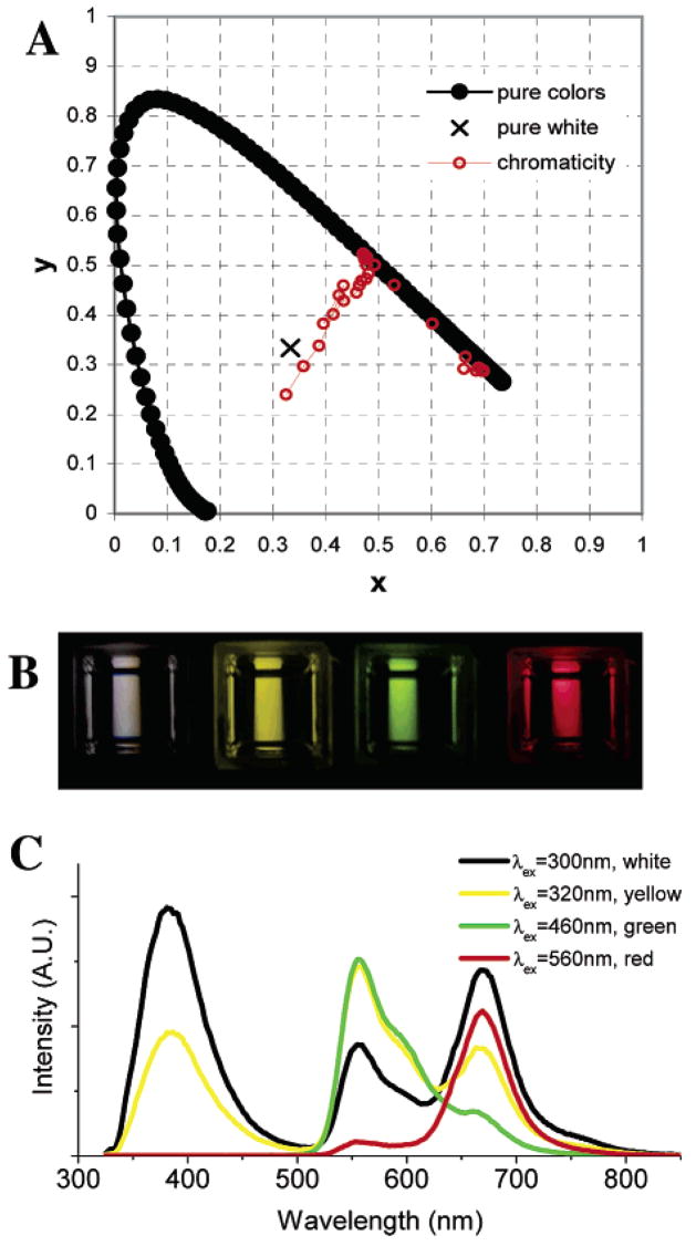
By changing either the excitation wavelength or the pH of the added buffer in DMSO, a variety of emission colors can be obtained. Excitation from 270 to 340 nm leads to three emission bands of varying intensities. Thus, the emission can appear either violet or near white. When excited from 340 to 410 nm, the color changes from near white to yellow owing to the disappearance of violet–blue emission and the increase of green emission. When excited from 420 to 540 nm, SNAFR-1 exhibits intensified green emission and comparatively weak red emission. As the excitation moves to longer wavelengths than 550 nm, that is, up to 650 nm, it exhibits red emission (Figure 8). As one can see from Figure 7, green and red emission is dependent on pH though blue emission is not. As a result, emission colors change significantly when the pH of the added buffer solution changes. The chromaticity of the emission as a function of both pH and excitation from 270 to 340 nm is summarized in Table 3. A complete table is located in Supporting Information. The chromaticity diagram obtained in DMSO using added buffer solution adjusted to pH 7 is shown in Figure 8A as an example. The data corresponding to other buffer pH values are also included in the Supporting Information.
Figure 8.
(A) Chromaticity coordinates for emission spectra collected with excitation wavelength between 270 and 650 nm plotted in a 1931 CIE (Commission Internationale de L’Eclairage) chromaticity diagram for a solution of 30 μM SNAFR-1 in DMSO with 0.25% phosphate buffer (50 mM, pH 7). (B) Photographs of 30 μM SNAFR-1 in DMSO with 0.25% phosphate buffer (50 mM, pH 7) when excited at 300, 320, 460, and 560 nm, respectively (from left to right), to afford emissions of near white, yellow, green, and red color. (C) The emission spectra corresponding to the photographs in panel B are shown.
Table 3.
Chromaticity of 30 μM SNAFR-1 in DMSO with 0.25% Buffer as a Function of pH of Added Phosphate Buffer Solutions
| pH 4 |
pH 5 |
pH 6 |
pH 7 |
pH 8 |
||||||
|---|---|---|---|---|---|---|---|---|---|---|
| λex | x | y | x | y | x | y | x | y | x | y |
| 270 nm | 0.37 | 0.34 | 0.36 | 0.32 | 0.33 | 0.27 | 0.36 | 0.30 | 0.30 | 0.18 |
| 280 nm | 0.40 | 0.39 | 0.39 | 0.38 | 0.37 | 0.33 | 0.36 | 0.30 | 0.33 | 0.23 |
| 290 nm | 0.40 | 0.39 | 0.39 | 0.38 | 0.37 | 0.33 | 0.39 | 0.34 | 0.33 | 0.22 |
| 300 nm | 0.42 | 0.42 | 0.41 | 0.41 | 0.40 | 0.36 | 0.41 | 0.40 | 0.36 | 0.25 |
| 310 nm | 0.44 | 0.46 | 0.44 | 0.45 | 0.42 | 0.42 | 0.43 | 0.44 | 0.38 | 0.31 |
| 320 nm | 0.45 | 0.48 | 0.45 | 0.47 | 0.43 | 0.45 | 0.43 | 0.46 | 0.39 | 0.36 |
| 330 nm | 0.46 | 0.49 | 0.45 | 0.48 | 0.44 | 0.47 | 0.40 | 0.38 | 0.39 | 0.38 |
| 340 nm | 0.43 | 0.44 | 0.42 | 0.43 | 0.40 | 0.40 | 0.44 | 0.43 | 0.35 | 0.28 |
Origin of the Violet–Blue Emission
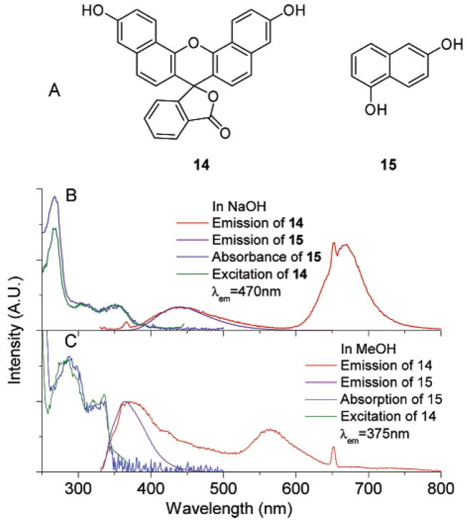
The origin of the green and red emission is discussed above. To investigate the origin of the violet–blue emission, we employ known benzo[c]-fluorescein (14) and 15 as model naphthyl-containing fluorophores. The blue emission of compound 14 is similar to that of compound 15 (Figure 9). Importantly, the excitation spectrum of 14 with emission monitored at 470 nm (blue band) overlays with the absorption spectrum of 15 (in 0.1 M NaOH, Figure 9B). A similar trend is observed in MeOH (Figure 9C). This implies that 14 and 15 have a similar mechanism of blue emission in both solvents.
Figure 9.
(A) Structures of compound 14 and 15; (B) emission spectra of 14 and 15 excited at 325 nm, excitation spectrum of 14 with emission monitored at 470 nm; absorption spectrum of 15; all compounds in 0.1 M NaOH; (C) emission spectra of 14 and 15 excited at 325 nm; excitation spectrum of 14 with emission monitored at 375 nm; absorption spectrum of 15. The concentrations of 14 in both solution are 10 μM. All the other solutions are 30 μM. All spectra are normalized to allow comparison.
We thus hypothesize that the blue emission of SNAFR-1 as well as known 14 arises from the isolated naphthyl moiety. In 14, the lactone form would isolate the naphthyl fluorophore. In organic solvents, it is well-known that the lactone form of xanthenes predominates. Thus, as expected, we observe a more intense blue emission than green emission in MeOH (Figure 9C). In 0.1 M NaOH solution, the equilibrium favors the formation of carboxylate anion instead of the lactone, leading to a more intense red emission (Figure 9B). However, the presence of some lactone (or covalently attached hydroxide, vide infra) apparently still induces some blue, naphthyl-derived emission.
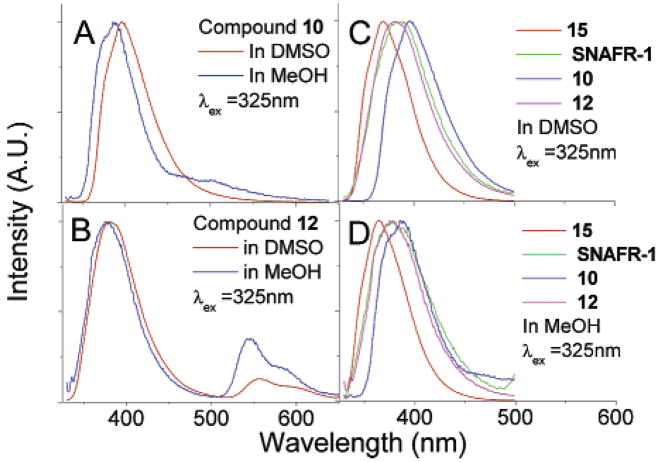
Though SNAFR-1 possesses no lactone to isolate the naphthalene fluorophore, its blue emission in various solvents resembles those of 14 and 15 (Figures 10C and D). This suggests an alternative mechanism to isolate the naphthalene unit, accounting for the violet-blue emission of SNAFR-1. Our experimental evidence shows that intermolecular nucleophilic addition readily occurs in the naphtho[a]- and [b]xanthene series. First, compound 10, the isolated adduct possessing a methyl ether at the bridging benzylic carbon, exhibits primarily violet–blue emission (Figure 10A). Second, compound 12, the methyl ether analogue of one tautomer of SNAFR-1, also undergoes nucleophilic addition to its central carbon, furnishing 16 (Scheme 5).
Figure 10.
(A) Fluorescence emission of 30 μM 10 in DMSO and MeOH; (B) fluorescence emission of 25 μM 12 in DMSO and MeOH; (C) overlay of the violet–blue emission of SNAFR-1 with other compounds possessing the isolated naphthalene moiety in DMSO; (D) overlay of the violet–blue emission of SNAFR-1 with other compounds possessing the isolated naphthalene moiety in MeOH. All fluorescence spectra are collected with an excitation wavelength at 325 nm. Solutions of SNAFR-1 and 15 are 30μM. All fluorescence spectra are normalized to the maximum of the violet–blue peak.
Scheme 5.
Equilibrium between Compounds 12 and 16a
a Methyl groups and corresponding peaks in Figure 11 are shown in the same color.
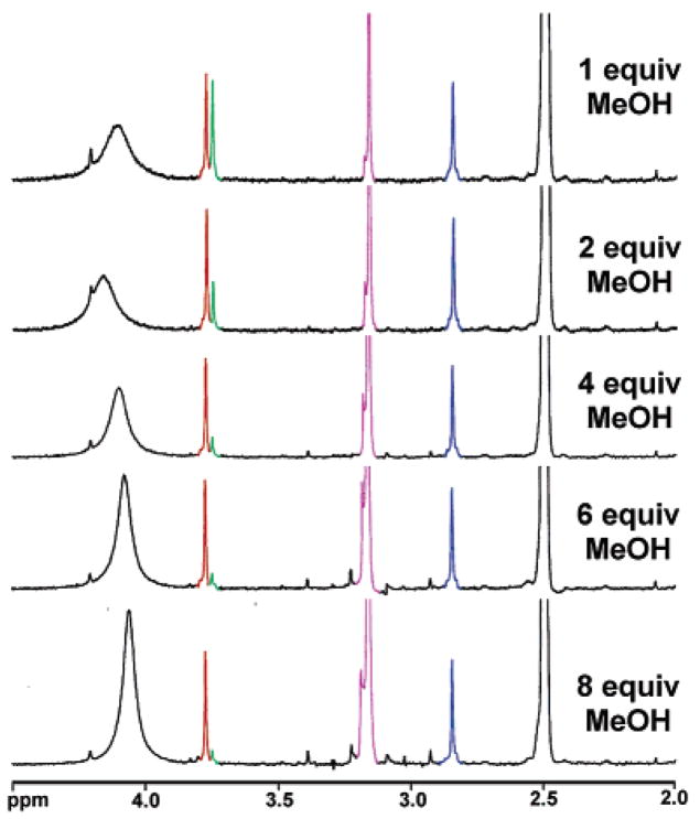
A study of the equilibrium between 12 and 16 using 1H NMR is shown in Figure 11. The resonances of the three methyl ether moieties of 12 and 16 are well-resolved. As the MeOH concentration increases, the relative proportion of compound 12 is observed to decrease. A MeOH solution of 12 displays an intense blue emission as well as a green emission (Figure 10B). The red emission of 12 is diminished compared to tautomerizable SNAFR-1. An overlay of the violet–blue emissions arising from 10, 12, 15, and SNAFR-1 in various solvents is shown in Figure 10. The similar spectral features, along with NMR and single-crystal X-ray structure evidence (e.g., the structure of 10 in Figure 3 possesses a predominant isolated naphthyl), help confirm the hypothesis that the isolated naphthyl is responsible for the violet–blue emission of this series of compounds. The presence of a trace amount of H2O apparently serves as the nucleophile in DMSO which leads to the isolated naphthyl unit. Alternative mechanisms (such as local excitation34) that might also lead to blue emission are currently under investigation.
Figure 11.
1H NMR study of the equilibrium between 12 and 16 in DMSO-d6. The concentration of compound 12 decreases as MeOH increases.
Dual Emission White Light Arising from Compound 12
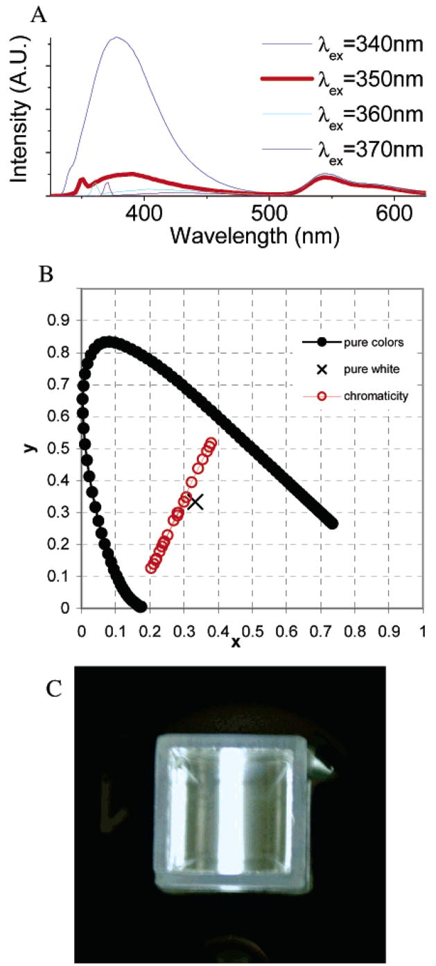
Figure 10B demonstrates that 12 in MeOH exhibits dual emission in the violet-blue and green spectral regions. In MeOH only a minimal amount of 12 remains in solution with the majority in the form of 16 (Scheme 5), leading to a dominant violet-blue emission (from ca. 330 to 450 nm) with a green emission (from ca. 520 to 620 nm) when excited below 340 nm. However, as has been shown for SNAFR-1, the relative intensities of these emission bands are dependent on excitation wavelength (Figure 12A). Excitation beyond 340 nm dramatically decreases the relative intensity of the blue emission band as excitation of the naphthyl unit becomes less efficient. When excited at 350 nm, the ratio of the two emission bands is nearly equal. The mixing of these emission bands again results in near white emission. The chromaticity diagram of 50 μM 12 in MeOH is shown in Figure 12B. A photograph of the white emission is shown in Figure 12C. Although two band white light has a poorer color rendering index (CRI) owing to the unbalanced red color,35 this result is of interest since currently two band white light is the main origin of white emission in white polymer light emitting diodes (WPLEDs).22a
Figure 12.
(A) The emission of 50 μM 12 in MeOH. When excited at 350 nm, 12 shows two emission bands of approximately equal intensity. (B) Shown are the chromaticity coordinates for emission spectra collected with excitation wavelength between 275 and 375 nm plotted in a 1931 CIE chromaticity diagram for a solution of 50 μM 12 in MeOH. (C) Photograph of white light of compound 12 in MeOH.
Live Cell Imaging
Organic fluorophores have found extensive applications in cell imaging. However, their drawbacks, such as narrow excitation, single, wide emission with a long tail, poor photostability, etc., limited their applications in some sophisticated applications such as multiplexing and real-time measurements. Few water soluble, long wavelength (λem > 600 nm), and photostable probes were reported. Though SNAFR-1 also shows a wide emission in neutral buffer solution, its unique properties of multiple emissions, wide excitation window, low cytotoxicity, and excellent photostability (vide infra) make it an ideal candidate for cellular imaging.
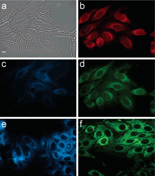
Cellular imaging studies reveal that SNAFR-1 readily enters HEp2 cells (Figure 13). SNAFR-1 localization is directed toward the lipophilic compartments, as there is a strong signal from the endoplasmic reticulum (ER) as well as some signal from mitochondria. The nuclei of the cells also show some SNAFR-1 fluorescence. This could be due to accumulation in the nuclear membrane or to intercalation into DNA. No obvious staining of the plasma membrane is observed. This is not surprising as the plasma membrane has a large surface area and, as such, a low surface brightness signal may not be detected. Three different filter sets, DAPI, FITC, and Texas Red, are applied corresponding to the blue, green, and red emission of SNAFR-1. Some autofluorescence from the cell is observed when DAPI is used. However, autofluorescence is minimal when longer wavelength filter sets such as FITC and Texas Red are used.
Figure 13.
(a) Phase contrast of cells stained with SNAFR-1; (b) fluorescence through Texas Red filter set with excitation 540–580 nm and emission 610 nm long pass; (c) fluorescence through DAPI filter set with excitation 330–370 nm and emission 420 nm long pass; (d) fluorescence through FITC filter set with excitation 460–500 nm and emission 510–560 nm; (e) endoplasmic reticulum stained with ERTracer Blue White (Molecular Probes); (f) mitochondria stained with MitoTracker Green (Molecular Probes). Scale bar is 10 μm.
Overnight incubation of cells with SNAFR-1 shows an overall increase in signal intensity compared to 30 min incubation and large vesicular formation within cells that do not colocalize with compound signal. At the concentrations tested, SNAFR-1 exhibits no toxic effects.
SNAFR-1 Exhibits Excellent Photostability
The photostability of SNAFR-1 is investigated in MeOH. It is much more photostable compared to fluorescein in 0.1 M NaOH. In MeOH SNAFR-1 can be excited efficiently at 488 nm, corresponding to an Ar ion laser line. This wavelength matches well with absorbance maximum (λabs = 493 nm) for fluorescein in aqueous base as well as that of SNAFR-1 (λabs = 489 nm) in MeOH. The photostability studies are conducted with solutions prepared to have an absorbance of 0.03 at 488 nm so that both SNAFR-1 and fluorescein solutions absorb the same number of photons when excited at 488 nm. The excitation band-pass is opened to 14 nm, the maximum allowed by the instrument. Fluorescence signal is collected using both the s and t channels of the instrument. S channel data are collected through the dual monochromator set at the emission maximum of a given fluorophore. T channel data are collected through a 550 nm long pass filter. High voltage for the photomultiplier tube (PMT) is set at 950 and 500 V for the s and t channels, respectively. Data are collected with a 0.1 s integration time at 0.1 s intervals for at least 1800 s. The signal is maintained within an acceptable range using neutral density filters (Omega optical, Brattleboro, VT). The photobleaching decay of each dye is plotted in Figure 14. SNAFR-1 shows excellent photostability during the time monitored, while fluorescein loses 20% of its fluorescence in only 30 min.
Figure 14.
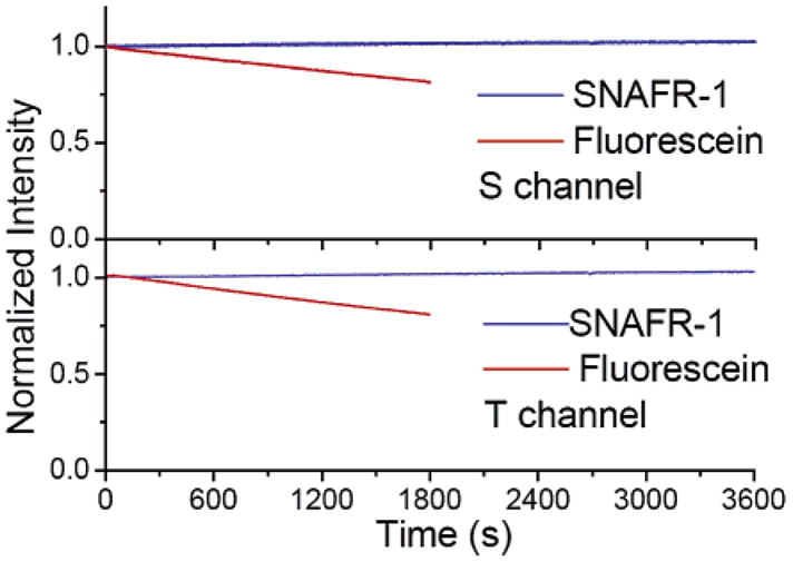
Photobleaching decay of SNAFR-1 in MeOH and fluorescein in 0.1 M NaOH monitored at emission maximum of each compound (top) and through a 550 nm long pass filter (bottom). The fluorescence intensity is normalized at time 0 s for each compound.
Conclusion
Wolfbeis and co-workers had predicted that novel benzannulated xanthenes would prove useful synthetic targets, particularly as intracellular pH probes. A new methodology for the synthesis of “missing” [a]- and [b]benzoxanthene regioisomers was described herein. We have shown that a type [a]benzofluorone, SNAFR-1, exhibits unique properties, including white light emission as well as excitation over a 400 nm range. Additionally, this compound shows promise for use in cellular imaging studies.
The dual visible emission maxima in the green and red spectral regions of the benzannulated xanthenes reported herein are dependent on both solution pH and excitation wavelength. We have found that benzannulated xanthenes emit blue light based on the equilibria involving nucleophilic addition at their benzylic carbon. Thus, tuning the intensities of the red, green, and blue emission wavelengths of SNAFR-1 to approximately equal intensities, via optimizing both solution parameters and excitation, renders it a red–green–blue (RGB) dye. This embodies a unique example of a simple dye that emits white light upon UV excitation. To realize materials applications, studies of SNAFR-1 and congeners in the solid state are needed. The synthesis and properties of these and related new fluorophores will be reported in due course.
Experimental Section
General Methods
1,6-Dimethoxynaphthalene was purchased from Wilshire Technologies. 2,4-Dimethoxybenzenephenone was prepared by a known procedure.36 All other reagents were purchased from Sigma-Aldrich and used as received without further purification except THF and CH2Cl2 which were dried using the Innovative Technologies solvent purification system. EtOAc, hexane, CHCl3, acetone, and MeOH were purchased from EMD biosciences and used as received. All reactions were carried out under an Ar atmosphere unless otherwise indicated. The TLC plates used were silica XHL TLC plates, glass backed, 250 μm, from Sorbent Technologies. The silica gel used was 60 Å standard grade with a distribution of 40–63 μm, from Sorbent Technologies. High-resolution MS (HRMS) and ESI spectra were obtained at the Mass Spectrometry Facility of Georgia State University, Atlanta, GA. NMR spectra were acquired in DMSO-d6 or CDCl3 on a Bruker DPX-250, DPX-300, or Avance-400 spectrometer. All δ values are reported with DMSO referenced at 2.49 ppm for 1H NMR and at 39.5 ppm for 13C NMR, or with CDCl3 referenced at 7.26 ppm for 1H NMR and at 77.0 ppm for 13C NMR.
X-ray Crystallography
Intensity data for X-ray crystallography was collected for compounds 4, 5, 6, 7, 8, 9, 10, and 13 at T = 110 K using graphite monochromated Mo Kα radiation (λ = 0.71073 Å) on a Nonius KappaCCD diffractometer fitted with an Oxford Cryostream cooler. Structures were solved by direct methods and refined by full-matrix least-squares, using SHELXL97.37 For all compounds, H atoms were visible in difference maps but were placed in idealized positions, torsional parameters were refined for methyl groups, and OH hydrogen positions were refined individually.
UV–Visible Absorption and Fluorescence Spectroscopy
UV–vis spectra were collected on Cary 50 Bio UV–vis spectrophotometer at room temperature using 1 cm quartz cuvette. Fluorescence spectra were collected on a Fluorolog-22Tau3 (Horiba Jobin Yvon, Edison, NJ). Solutions were placed in a 1 cm path length quartz cell (Starna Cells, Atascadero, CA). Emission spectra were collected following excitation with a 450 W xenon arc lamp. A dual monochromator was used to select light of 325, 488, 514, 543, and 633 nm (bandpass = 1 nm). Emission wavelengths were scanned with 1 nm step sizes using a dual monochromator (band-pass = 4 nm). Integration time was set to 0.1 s per point, and 950 V was applied to a Hamamatsu R928 PMT. Excitation spectra were monitored with an emission and excitation band-pass of 4 and 1 nm, respectively. All spectra were corrected through division by signal from a reference channel. Excitation emission matrixes (EEMs) were collected over various spectral regions using 2 nm step sizes for emission and 10 nm step sizes for excitation. An estimate of the fluorescence quantum yield was obtained as reported.38 Quantum yields are relative to rhodamine 6G in EtOH. An assumption was made that rhodamine 6G has a quantum yield of 1 when dissolved in EtOH.
Live-Cell Measurements
HEp2 cells were obtained from ATCC and maintained in a 50:50 mixture of DMEM/Advanced MEM (Invitrogen) supplemented with 5% FBS (Invitrogen) and Primocin as antibiotic (Invivogen). Cells were subcultured twice weekly to maintain working stocks. HEp2 cells were seeded onto LabTek ll chamber coverslips and allowed to grow for 48 h. SNAFR-1 was first prepared as a 10 mM stock in DMSO and then diluted directly into medium to 10μM. Cells were then fed medium containing SNAFR-1 for 30 min. Slides were then washed three times with medium containing 50 mM HEPES pH 7.2 and examined using a Zeiss Labovert 200 M microscope fitted with a standard Texas Red filter set (Chroma Technology Corp.). The images were acquired using a Zeiss AxioCam MRm digital camera. Mitochondria were stained using a 250 nM MitoTracker Green FM, and endoplasmic reticulum were stained using 1 μM ER-Tracker Green (both from Molecular Probes) by incubating cells for 30 min with the appropriate dye and washing as above. The organelle stains were visualized using a standard FITC filter set (Chroma Technology Corp.) Compound toxicity was tested by plating 7500 HEp2 cells per well on a Costar 96-well plate. The cells were allowed to grow for 48 h and then were fed medium containing 2-fold dilutions of SNAFR-1 ranging from 10 to 1.25 μM. Saponin (0.1%, Sigma) was used as a negative control. Cells were then incubated for 24 h. For normalization purposes, untreated cells were considered 100% viable, and cells treated with 0.1% saponin were considered 0% viable. Viability was measured using the CellTiter Blue Cell Viability assay (Promega) as per manufacturer’s instructions. Fluorescence signal was detected using an excitation wavelength of 520 nm and emission wavelength of 584 nm.
Supplementary Material
1H, 13C NMR spectra, mass spectra of compounds 4–10, 12, SNAFR-1, and 13; crystallographic information files (CIFs) and ORTEP graphs for compounds 4–10 and 13; cytotoxicity study; spectral information of 10, SNAFR-1, 12, 14; apparent pKa values in DMSO containing 0.25% phosphate buffer; chromaticity diagram of 10, SNAFR-1, 12, and 14 at various conditions are included. This material is available free of charge via the Internet at http://pubs.acs.org.
Acknowledgments
The authors thank Dr. William E. Crowe and Dr. Rafael Cueto for insightful discussions and Alexander D. Wong, Michael C. Touchy II, Louise A. Corle, and Francis S. Sicard for their diligent lab work and also very gratefully acknowledge the generous support of the National Institutes of Health (Grant R01 EB002044). The purchase of the Nonius Kappa CCD diffractometer was made possible by Grant No. LEQSF-(1999–2000)-ESH-TR-13, administered by the Louisiana Board of Regents.
References
- 1.(a) Terenin AN, Kariakin A. Nature. 1947;159:881–882. doi: 10.1038/159881a0. [DOI] [PubMed] [Google Scholar]; (b) Forster T. Z Elektrochem. 1950;54:531–535. [Google Scholar]
- 2.(a) Lippert E, Lüder W, Boos H. Proc Int Meet Mol Spectrosc, 4th. 1962;1959:443–457. [Google Scholar]; (b) Zachariasse KA, von der Haar T, Hebecker A, Leinhos U, Kuhnle W. Pure Appl Chem. 1993;65:1745–1750. [Google Scholar]
- 3.Loren JC, Siegel JS. Angew Chem, Int Ed. 2001;40:754–757. [PubMed] [Google Scholar]
- 4.(a) Whitaker JE, Haugland RP, Prendergast FG. Anal Biochem. 1991;194:330–344. doi: 10.1016/0003-2697(91)90237-n. [DOI] [PubMed] [Google Scholar]; (b) Liu J, Diwu Z, Leung WY. Bioorg Med Chem Lett. 2001;11:2903–2905. doi: 10.1016/s0960-894x(01)00595-9. [DOI] [PubMed] [Google Scholar]
- 5.(a) Klymchenko AS, Ozturk T, Demchenko AP. Tetrohedron Lett. 2002;43:7079–7082. [Google Scholar]; (b) Ameer-Beg S, Ormson SM, Poteau X, Brown RG, Foggi P, Bussotti L, Neuwahl FVR. J Phys Chem A. 2004;108:6938–6943. [Google Scholar]; (c) Klymchenko AS, Mèly Y. Tetrahedron Lett. 2004;45:8391–8394. [Google Scholar]; (d) Chou PT, Huang CH, Pu SC, Cheng YM, Liu YH, Wang Y, Chen CT. J Phys Chem A. 2004;108:6452–6454. [Google Scholar]
- 6.Solntsev KM, Sullivan EN, Tolbert LM, Ashkenazi S, Leiderman P, Huppert D. J Am Chem Soc. 2004;126:12701–12708. doi: 10.1021/ja047821e. [DOI] [PubMed] [Google Scholar]
- 7.Solntsev KM, Clower CE, Tolbert LM, Huppert D. J Am Chem Soc. 2005;127:8534–8544. doi: 10.1021/ja0514545. [DOI] [PubMed] [Google Scholar]
- 8.(a) Demeter A, Bèrces T, Biczòk L, Wintgens V, Valat P, Kossanyi J. J Chem Soc, Faraday Trans. 1994;90:2635–2641. [Google Scholar]; (b) Cao H, McGill T, Heagy MD. J Org Chem. 2004;69:2959–2966. doi: 10.1021/jo035760h. [DOI] [PubMed] [Google Scholar]
- 9.(a) Bettermann H, Bienioschek M, Ippendorf H, Martin HD. Angew Chem, Int Ed Engl. 1992;31:1042. [Google Scholar]; (b) Mimuro M, Nagashima U, Nagaoka S, Nishimura Y, Takaichi S, Katoh T, Yamazaki I. Chem Phys Lett. 1992;191:219. [Google Scholar]; (c) Wang Y, Hu X. J Am Chem Soc. 2002;124:8445–8451. doi: 10.1021/ja025618i. [DOI] [PubMed] [Google Scholar]
- 10.Rurack K, Danel A, Rotkiewicz K, Grabka D, Spieles M, Rettig W. Org Lett. 2002;4:4647–4650. doi: 10.1021/ol027025i. [DOI] [PubMed] [Google Scholar]
- 11.Recent review: Shizuka H. Acc Chem Res. 1985;18:141–147.Formosinho SJ, Arnaut LG. J Photochem Photobiol A. 1993;75:21–48.Arnaut LG, Formosinho SJ. J Photochem Photobiol A. 1993;75:1–20.Scheiner S. J Phys Chem A. 2000;104:5898–5909.Tolbert LM, Solntsev KM. Acc Chem Res. 2002;35:19–27. doi: 10.1021/ar990109f.
- 12.Recent reviews: Rettig W. Angew Chem, Int Ed Engl. 1986;25:971–988.Rettig W, Lapouyade R. Fluorescent Probes Based on Twisted Intramolecular Charge Transfer (TITC) States and Other Adiabatic Photoreactions. In: Lakowicz JR, editor. Topics in Fluorescence Spectroscopy. Vol. 4. Plenum Publishing Corporation; New York: 1994. pp. 109–149.Grabowski ZR, Rotkiewicz K, Rettig W. Chem Rev. 2003;103:3899–4031. doi: 10.1021/cr940745l.
- 13.(a) Inoue Y, Jiang P, Tsukada E, Wada T, Shimizu H, Tai A, Ishikawa M. J Am Chem Soc. 2002;124:6942–6949. doi: 10.1021/ja016858l. [DOI] [PubMed] [Google Scholar]; (b) Klymchenko AS, Demchenko AP. J Am Chem Soc. 2002;124:12372–12379. doi: 10.1021/ja027669l. [DOI] [PubMed] [Google Scholar]; (c) Cao H, Chang V, Hernandez R, Heagy MD. J Org Chem. 2005;70:4929–4934. doi: 10.1021/jo050157f. [DOI] [PubMed] [Google Scholar]
- 14.Kermis HR, Kostov Y, Harms P, Rao G. Biotechnol Prog. 2002;18:1047–1053. doi: 10.1021/bp0255560. [DOI] [PubMed] [Google Scholar]
- 15.(a) Tsien RY. Methods Cell Biol. 1989;30:127–156. doi: 10.1016/s0091-679x(08)60978-4. [DOI] [PubMed] [Google Scholar]; (b) Haugland RP, Johnson ID. In: Fluorescent and Luminescent Probes for Biological Activity: A Practical Guide to Technology for Quantitative Real-Time Analysis. 2. Mason WT, editor. Academic; New York: 1999. pp. 40–50. [Google Scholar]; (c) Charier S, Ruel O, Baudin J-B, Alcor D, Allemand J-F, Meglio A, Jullien L. Angew Chem, Intl Ed Engl. 2004;43:4785–4788. doi: 10.1002/anie.200460557. [DOI] [PubMed] [Google Scholar]; (d) Aslan K, Lakowicz JR, Szmacinski H, Geddes CD. J Fluoresc. 2005;15:37–40. doi: 10.1007/s10895-005-0211-0. [DOI] [PMC free article] [PubMed] [Google Scholar]; (e) Wang Z, Zheng G, Lu P. Org Lett. 2005;7:3669–3672. doi: 10.1021/ol051211h. [DOI] [PubMed] [Google Scholar]; (f) Bizzarri R, Arcangeli C, Arosio D, Ricci F, Faraci P, Cardarelli F, Beltram F. Biophys J. 2006;90:3300–3314. doi: 10.1529/biophysj.105.074708. [DOI] [PMC free article] [PubMed] [Google Scholar]
- 16.(a) Dey J, Warner IM. J Phys Chem A. 1997;101:4827–4878. [Google Scholar]; (b) Haidekker MA, Brady TP, Lichlyter D, Theodorakis EA. J Am Chem Soc. 2006;128:398–399. doi: 10.1021/ja056370a. [DOI] [PubMed] [Google Scholar]; (c) Milich K, Akers W, Haidekker MA. Sens Lett. 2005;3:237–243. [Google Scholar]
- 17.(a) Scheenen WJJM, Hofer AM, Pozzan T. In: Cell Biology: A Laboratory Handbook. 2. Celis JE, editor. Vol. 3. Academic; New York: 1998. pp. 363–374. [Google Scholar]; (b) Bkaily G, Jacques D, Pothier P. Methods Enzymol. 1999;307:119–135. doi: 10.1016/s0076-6879(99)07010-x. [DOI] [PubMed] [Google Scholar]; (c) Chang CJ, Jaworski J, Nolan EM, Sheng M, Lippard SJ. Proc Natl Acad Sci USA. 2004;101:1129–1134. doi: 10.1073/pnas.0308079100. [DOI] [PMC free article] [PubMed] [Google Scholar]
- 18.(a) van Erp PE, Jansen MJ, de Jongh GJ, Boezeman JB, Schalkwijk J. Cytometry. 1991;12:127–132. doi: 10.1002/cyto.990120205. [DOI] [PubMed] [Google Scholar]; (b) Lucas B, Remaut K, Sanders NN, Braeckmans K, De Smedt SC. Demeester J Biochem. 2000;44:9905–9912. doi: 10.1021/bi0476883. [DOI] [PubMed] [Google Scholar]; (c) Honda A, Adams SR, Sawyer CL, Lev-Ram V, Tsien RY, Dostmann WRG. Proc Natl Acad Sci USA. 2001;98:2437–2442. doi: 10.1073/pnas.051631298. [DOI] [PMC free article] [PubMed] [Google Scholar]; (d) Lohr C. Cell Calcium. 2003;34:295–303. doi: 10.1016/s0143-4160(03)00105-2. [DOI] [PubMed] [Google Scholar]; (e) Yishai Y, Fixler D, Cohen-Kashi M, Zurgil N, Deutsch M. Phys Med Biol. 2003;48:2255–2268. doi: 10.1088/0031-9155/48/15/301. [DOI] [PubMed] [Google Scholar]; (f) Taki M, Wolford JL, O’Halloran TV. J Am Chem Soc. 2004;126:712–713. doi: 10.1021/ja039073j. [DOI] [PubMed] [Google Scholar]
- 19.Fabian WMF, Schuppler S, Wolfbeis OS. J Chem Soc, Perkin Trans 2. 1996;5:853–856. [Google Scholar]
- 20.Yang Y, Escobedo JO, Wong A, Schowalter CM, Touchy MC, Jiao L, Crowe WE, Fronczek FR, Strongin RM. J Org Chem. 2005;70:6907–6912. doi: 10.1021/jo051002a. [DOI] [PMC free article] [PubMed] [Google Scholar]
- 21.(a) Adachi C, Baldo MA, Thompson ME, Forrest SR. J Appl Phys. 2001;90:5048–5051. [Google Scholar]; (b) Xie W, Liu S, Zhao Y. J Phys D: Appl Phys. 2003;36:1246–1248. [Google Scholar]; (c) Jia WL, Feng XD, Bai DR, Lu ZH, Wang S, Vamvounis G. Chem Mater. 2005;17:164–170. [Google Scholar]; (d) Sun Y, Giebink NC, Kanno H, Ma B, Thompson ME, Forrest SR. Nature. 2006;404:908–912. doi: 10.1038/nature04645. [DOI] [PubMed] [Google Scholar]
- 22.(a) Chu HY, Lee JI, Do LM, Zyung T, Jung BJ, Shim HK, Jang J. Mol Cryst Liq Cryst. 2003;405:119–125. [Google Scholar]; (b) Xu Y, Peng J, Jiang J, Xu W, Yang W, Cao Y. Appl Phys Lett. 2005;87:193502/1–193502/3. [Google Scholar]; (c) Jou JH, Sun MC, Chou HH, Li CH. Appl Phys Lett. 2005;87:043508/1–043508/3. [Google Scholar]; (d) Niu YH, Tung YL, Chi Y, Shu CF, Kim JH, Chen B, Luo J, Carty AJ, Jen AKY. Chem Mater. 2005;17:3532–3536. [Google Scholar]; (e) Jou JH, Chiu YS, Wang RY, Hu HC, Wang CP, Lin HW. Org Electron. 2006;7:8–15. [Google Scholar]
- 23.(a) Comiskey B, Albert JD, Yoshizawa H, Jacobson J. Nature. 1998;394:253–255. [Google Scholar]; (b) Rogers JA. Science. 2001;291:1502–1503. doi: 10.1126/science.291.5508.1502. [DOI] [PubMed] [Google Scholar]; (c) Andersson P, Nilsson D, Svensson PO, Chen MX, Malmstrom A, Remonen T, Kugler T, Berggren M. Adv Mater. 2002;14:1460–1464. [Google Scholar]; (d) Hayes RA, Feenstra BJ. Nature. 2003;425:383–385. doi: 10.1038/nature01988. [DOI] [PubMed] [Google Scholar]; (e) Chen Y, Au J, Kazlas P, Ritenour A, Gates H, McCreary M. Nature. 2003;423:136–136. doi: 10.1038/423136a. [DOI] [PubMed] [Google Scholar]; (f) Deng WQ, Flood AH, Stoddart JF, Goddard WA., III J Am Chem Soc. 2005;127:15994–15995. doi: 10.1021/ja0431298. [DOI] [PubMed] [Google Scholar]
- 24.(a) Hebner TR, Sturn JC. Appl Phys Lett. 1998;73:1775–1777. [Google Scholar]; (b) Ko CW, Tao YT. Appl Phys Lett. 2001;79:4234–4236. [Google Scholar]; (c) Cheon KO, Shinar J. Appl Phys Lett. 2002;81:1738–1740. [Google Scholar]; (d) Mazzeo M, Pisignano D, Della Sala F, Thompson J, Blyth RIR, Gigli G, Cingolani R, Sotgiu G, Barbarella G. App Phys Lett. 2003;82:334–336. [Google Scholar]; (e) Qin Dashan, Tao Ye. Appl Phys Lett. 2005;86:113507/1–113507/3. [Google Scholar]
- 25.Bowers MJ, II, McBride JR, Rosenthal SJ. J Am Chem Soc. 2005;127:15378–15379. doi: 10.1021/ja055470d. [DOI] [PubMed] [Google Scholar]
- 26.Hutchison K, Gao J, Schick G, Rubin Y, Wudl F. J Am Chem Soc. 1999;121:5611–5612. [Google Scholar]
- 27.Liu Y, Nishiura M, Wang Y, Hou Z. J Am Chem Soc. 2006;128:5592–5593. doi: 10.1021/ja058188f. [DOI] [PubMed] [Google Scholar]
- 28.Furuta PT, Deng L, Garon S, Thompson ME, Frechet JMJ. J Am Chem Soc. 2004;126:15388–15389. doi: 10.1021/ja0446247. [DOI] [PubMed] [Google Scholar]
- 29.Liao YC, Lin CH, Wang SL. J Am Chem Soc. 2005;127:9986–9987. doi: 10.1021/ja0512879. [DOI] [PubMed] [Google Scholar]
- 30.Bacci JP, Kearney AM, Van Vranken DL. J Org Chem. 2005;70:9051–9053. doi: 10.1021/jo051243i. and references therein. [DOI] [PubMed] [Google Scholar]
- 31.Anette MJ, Charlotta M, Uli H. J Org Chem. 1986;51:5252–5258. [Google Scholar]
- 32.Adding 0.25% distilled water instead of 0.25% phosphate buffer does not lead to any significant change of spectral shape.
- 33.(a) Chromaticity coordinates x, y, and z are derived by calculating the fractional components of the tristimulus values thus: x = X/(X + Y + Z), y = Y/(X + Y + Z), z = Z/(X + Y + Z). Tristimulus values are the amounts of three primaries that specify a color stimulus. The CIE 1931 tristimulus values are denoted as X, Y, and Z. All possible sets of tristimulus values can be represented in a two-dimensional plot of two of these chromaticity coordinates and by convention x and y are always used. A plot of this type is referred to as a chromaticity diagram; http://www.colourware.co.uk/. (b) http://hyperphysics.phy-astr.gsu.edu/hbase/vision/cie.html#c2Wyszecki G. Colorimetry. In: Driscoll WG, Vaughan W, editors. Handbook of Optics. McGraw-Hill Book Company; New York: 1978. pp. 1–15.
- 34.Zilberg S, Haas Y. J Phys Chem A. 2002;106:1–10. [Google Scholar]
- 35.Zakauskas A, Shur M, Gaska R. Introduction to solid-state lighting. Wiley-Interscience; New York: 2002. p. 130. [Google Scholar]
- 36.Ouk S, Thiebaud S, Borredon E, Legars P. Tetrahedron Lett. 2002;43:2661–2663. [Google Scholar]
- 37.Sheldrick GM. SHELXL97. University of Göttingen; Göttingen, Germany: 1997. [Google Scholar]
- 38.Williams ATR, Winfield SA, Miller JN. Analyst. 1983;108:1067–1071. [Google Scholar]
Associated Data
This section collects any data citations, data availability statements, or supplementary materials included in this article.
Supplementary Materials
1H, 13C NMR spectra, mass spectra of compounds 4–10, 12, SNAFR-1, and 13; crystallographic information files (CIFs) and ORTEP graphs for compounds 4–10 and 13; cytotoxicity study; spectral information of 10, SNAFR-1, 12, 14; apparent pKa values in DMSO containing 0.25% phosphate buffer; chromaticity diagram of 10, SNAFR-1, 12, and 14 at various conditions are included. This material is available free of charge via the Internet at http://pubs.acs.org.


