Abstract
Dynein motors move various cargos along microtubules within the cytoplasm and power the beating of cilia and flagella. An unusual feature of dynein is that its microtubule-binding domain (MTBD) is separated from its ring-shaped AAA+ adenosine triphosphatase (ATPase) domain by a 15-nanometer coiled-coil stalk. We report the crystal structure of the mouse cytoplasmic dynein MTBD and a portion of the coiled coil, which supports a mechanism by which the ATPase domain and MTBD may communicate through a shift in the heptad registry of the coiled coil. Surprisingly, functional data suggest that the MTBD, and not the ATPase domain, is the main determinant of the direction of dynein motility.
Dyneins are AAA+ adenosine triphos-phatases (ATPases) that power minus end–directed movement along microtubules (1). The cytoplasmic form of dynein serves many cellular functions including regulation of the mitotic checkpoint (2), organization of the Golgi apparatus (3), and the transport of vesicles, viruses, and mRNAs (4). Several human diseases, such as lissencephaly (4), primary ciliary dyskinesia (5), neural degeneration (6), and male infertility (7), result from dynein dysfunction.
The motor region of dynein (Fig. 1A) consists of a ring of AAA+ domains (four of which bind and hydrolyze ATP), a mechanical element (termed the “linker”) that is likely involved in driving motility (8, 9), and a ~15-nm “stalk” that has a microtubule-binding domain (MTBD) at its tip. The stalk, which emerges from AAA4 (the fourth nucleotide-binding AAA+ domain in the ring), extends as one α helix of an antiparallel coiled coil (termed CC1), forms the small, globular MTBD, and then returns as the partner helix of the coiled coil (CC2) and joins AAA5 (a non–nucleotide-binding AAA+ domain) (10). The separation of the AAA+ ring from the MTBD by a long and somewhat flexible coiled coil (8) distinguishes dynein from kinesin and myosin, where the polymer-binding site and catalytic site are integrated within a single globular motor domain.
Fig. 1.
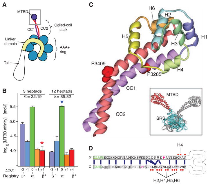
Crystal structure of the dynein microtubule-binding domain. (A) Cartoon of a dynein motor (heavy chain). A gray box highlights the region of the stalk and microtubule-binding domain (MTBD) whose atomic structure is reported. (B) Effect of different heptad registries on microtubule-binding affinity of monomeric SRS-MTBD fusions with stalks of one-quarter and full native length. Paired numbers designating each construct (e.g., 22:19) indicate the number of residues between the SRS splice site and the proline marking the stalk-MTBD boundary for CC1 and CC2, respectively. (C) Crystal structure of the MTBD, showing the two α helices of the stalk (CC1, purple; CC2, red) that extend out of the SRS coiled coil and connect to the six-helix bundle (H1 to H6) forming the MTBD proper. A staggered pair of conserved prolines (Pro3285 and Pro3409) are associated with a kink in the stalk. Inset: dimeric SRS-MTBD fusion protein (chain A, blue SRS with red MTBD; chain B, gray). (D) Schematic diagram of the stalk helices (CC1 and CC2) showing the heptad repeat hydrophobic contacts (blue lines) in the core of the coiled coil. The regularity of this repeat is disrupted between the conserved prolines (magenta), resulting in a half-heptad shift in coiled-coil registry. Residues in the SRS are shown in green. Residues in CC1 and CC2 that contact the other helices in MTBD are marked with red dots Abbreviations: A, Ala; C, Cys; D, Asp; E, Glu; F, Phe; G, Gly; H, His; I, Ile; K, Lys; L, Leu; M, Met; N, Asn; P, Pro; Q, Gln; R, Arg; S, Ser; T, Thr; V, Val; W, Trp; Y, Tyr.
The unusual separation of ATPase and MTBD in dynein raises questions about its motility mechanism. First, how might bidirectional communication be relayed through a 15-nm coiled coil such that, in one direction, microtubule binding at the MTBD stimulates ATP turnover in the AAA+ ring, while in the other direction, chemical transitions in the AAA+ ring control the strength of microtubule binding at the MTBD? Second, how does a flexible coiled-coil stalk orient the AAA+ ring such that a force-producing movement of the linker element (with respect to the AAA+ domains) generates a displacement of the cargo toward the minus end of the microtubule?
These questions cannot be addressed without atomic-level structural information about the MTBD and the stalk. Given the large size of the minimal dynein motor domain (>320 kD of the >500-kD heavy-chain polypeptide), we sought to obtain a crystal structure of the MTBD and the distal portion of the coiled-coil stalk of mouse cytoplasmic dynein as a fusion with seryl tRNA-synthetase (SRS) from Thermus thermophilus. Previous work showed that such fusion proteins retain the ability to bind to microtubules and that their affinity for microtubules can be varied by changing the register in which the hydrophobic heptad periodicity of the coiled-coil stalk is fused to that of the SRS (11). This led to a model in which shifts in registry of the putative coiled coil could control the transition between weak and strong binding states in dynein’s motility cycle.
We found that the pattern of two alternate registries (α andβ)—having high and low microtubule-binding affinity, respectively—continues along the full length of the stalk (Fig. 1B, fig. S1, and table S1). Although crystals of an SRS-MTBD fusion in a strong microtubule-binding form were not obtained, we succeeded in crystallizing a thermally stable (table S2), weak-binding fusion protein (Fig. 1B, red star). The 2.3 Å structure was phased by molecular replacement, using the SRS as a search model, and refined to an Rfree of 0.25 (see table S3 for crystallographic statistics). The SRS was present as a dimer, leading to two copies of the MTBD in the asymmetric unit (Fig. 1C, inset).
The coiled coil of the SRS proceeds smoothly into the coiled coil of the dynein stalk, and the distal MTBD consists of a bundle of six α helices (H1 to H6, Fig. 1C). In the basal region of the stalk, CC1 and CC2 form a characteristic anti-parallel coiled coil with their registry continuing that of the SRS. After three heptads, the path of the coiled coil is bent by a pair of staggered, highly conserved prolines (Pro3285 in CC1 and Pro3409 in CC2; fig. S2), with the regular packing of hydrophobic residues in the coiled-coil core being disrupted in the region between the prolines (Fig. 1, C and D). When the heptad registry resumes after the prolines, the registry of CC1 has slipped by one half-heptad relative to that of CC2. The distal portion of CC2 makes extensive hydrophobic interactions with H2, H4, H5, and H6, whereas CC1 makes only a few contacts with H4 (Fig. 1D) before joining directly into H1. This asymmetry suggests that the interface between the stalk and the MTBD serves an important role in the dynein mechanism.
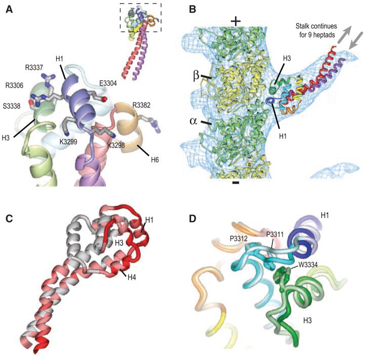
Opposite the point of entry of the coiled coil in the MTBD are three helices (H1, H3, and H6) that contain a high density of conserved, surface-accessible residues (fig. S3, A and B); this surface is largely electropositive (fig. S3C), similar to the microtubule docking site of kinesin (12). Mutation of several of these conserved residues to alanine interferes with the binding of Dictyostelium cytoplasmic dynein to microtubules (13), making this a likely contact site with the microtubule (Fig. 2A and fig. S3, D and E). In support of this model, we obtained a cryo–electron microscopy (cryo-EM) helical reconstruction (Fig. 2B, fig. S4, A to C, and movie S1) of microtubules decorated with a strong microtubule-binding SRS-MTBD construct with a 12-heptad stalk (blue triangle in Fig. 1B).
Fig. 2.
Microtubule-binding surface of the dynein MTBD. (A) Close-up view of the MTBD, showing the putative microtubule-binding helices H1, H3, and H6. Residues that abolish binding when mutated to alanine (13) are shown in stick representation. The inset shows this interface (boxed) with respect to the whole MTBD structure. (B) A model of the dynein MTBD (crystal structure shown and colored as in Fig. 1C) bound to a tubulin protofilament (α tubulin, green; β tubulin, yellow). Crystal structures were docked into a single protofilament cut from the cryo-EM electron density map of a microtubule decorated with a monomeric, tight-binding (α registry) SRS-MTBD construct containing 12 heptads of dynein stalk (SRS-MTBD-85:82). The plus and minus signs indicate microtubule polarity. The SRS and nine basal heptad repeats of the stalk are not visible in the reconstructed image (gray arrows). (C) Conformational differences between the A and B MTBD monomers on an SRS dimer. Regions of high RMS difference are colored dark red. (D) Close-up of the H1–H3 interface. Aligned MTBDs are shown in light (chain B) and dark (chain A) coloring. The contact between the highly conserved Pro3311 and Trp3334 residues is broken in chain B.
The MTBD and a portion of the stalk were visible in the EM maps, but density was not observed for the distal nine heptads of this construct, most likely because the coiled coil is flexible and not fixed in one conformation. Our EM reconstruction contains more density for the stalk region but otherwise agrees well with a previous cryo-EM study (14). Our crystal structure of the MTBD stalk fits well into the cryo-EM density map (Fig. 2B). This docking places the MTBD helices H1 and H3—the candidate microtubule binding helices, according to mutagenesis studies—in a groove at the interface between the α and β tubulin subunits, which is the same location that kinesin motors use for binding to microtubules (fig. S4D) (14–16). In addition to locating the microtubule-binding interface, these data suggest that the overall shape of our weak-binding crystal structure is similar to that of a strong-binding construct and to native dynein bound to microtubules. However, at finer resolution, we cannot be sure whether our structure corresponds to an exact intermediate in native dynein’s motility cycle.
In addition, the proposed microtubule-binding interface shows the greatest root-mean-square (RMS) differences between the two copies of the MTBD attached to the SRS dimer (dark red in Fig. 2C). Although these variations are driven by differences in crystal packing, they likely reflect regions of conformational flexibility in the MTBD that might rearrange in response to different nucleotide states in the catalytic domain (other regions with crystal contacts show little RMS deviation; fig. S5). A possible linchpin for conformational movements in the microtubule-binding helices is a contact between a highly conserved (fig. S2) proline (Pro3311) in H1 and a tryptophan (Trp3334) in H3; this contact is present in one MTBD of the SRS dimer but is disrupted in the other (Fig. 2D).
The direct connectivity of CC1 with H1 (a conformationally flexible helix at a microtubule-binding interface) and CC1’s limited contacts with the rest of the MTBD suggest that movement of CC1 is responsible for bidirectional communication along the stalk. We propose that strong microtubule binding changes the conformations of H1, H3, and H4. This results in a movement of CC1 relative to CC2 that propagates to the AAA+ ring and stimulates a rate-limiting chemical transition in the ATPase cycle. A subsequent nucleotide-dependent change in the AAA+ ring then drives the opposite movement of CC1, leading to a reduction in affinity of the MTBD for microtubules.
With respect to the magnitude of sliding, it is possible that communication might occur through a small displacement of the helix similar to that proposed for bacterial chemotaxis receptors (17). However, we favor the idea that CC1 is displaced by four residues (fig. S6) relative to a stationary CC2. This model is consistent with biochemical data from SRS fusion proteins (Fig. 1B) (11), which show that forcing a change in registry of the stalk at one end can affect the binding affinity of the MTBD, even over a distance of 12 heptad repeats (12 nm). The region between the staggered pair of proline residues (Fig. 1D) may be particularly important for such a conformational change mechanism. This region could facilitate a piston-like movement of CC1 relative to CC2. Alternatively, the slip in heptad register seen in this region of our crystal structure may serve as the starting point for a domino-like movement involving local melting and reformation of the coiled coil that propagates the register change from one end of the stalk to the other.
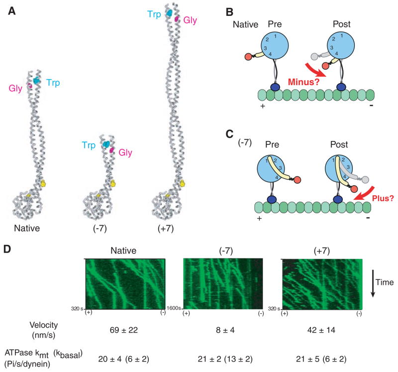
We next sought to examine the role of the MTBD in determining the direction of dynein motility. The most widely cited model (8) for dynein proposes that motility is driven by a minus end–directed swing of the linker domain (Fig. 3B, red arrow). In this model, the MTBD and stalk hold the AAA+ ring in such an orientation that the power stroke is directed along the microtubule axis toward the minus end. To investigate whether the MTBD stalk serves such a role in dynein’s mechanism, we engineered an artificially dimerized Saccharomyces cerevisiae cytoplasmic dynein (18) with its stalk coiled coil either lengthened or shortened by seven heptads (fig. S5). On the basis of the coiled-coil nature of the dynein stalk proximal to the proline-associated kink, these stalk length changes would be predicted to rotate the AAA+ ring by 180° (Fig. 3, A and C) and reverse the direction of dynein movement according to the model in Fig. 3B. Even though the native length of the stalk appears to be conserved in all dyneins, we found that dynein constructs with markedly shortened or lengthened stalks could still move processively along microtubules, albeit with reduced velocities. The much slower velocity of the −7 construct may be the result of some degree of uncoupling between the MTBD and AAA+ ring, as reflected by its elevated basal ATPase rate. Remarkably, the movement of both mutants remained minus end–directed (Fig. 3D and movies S2 to S4), which suggests that the orientation of the AAA+ domain does not determine the direction of dynein movement along a microtubule.
Fig. 3.
Rotation of the AAA+ ring by insertion or deletion of stalk sequence does not affect the direction of dynein movement. (A) Model of native dynein stalk (at left), showing the pair of conserved prolines (yellow spacefill) marking the MTBD and the conserved Trp-Gly pair that mark the top of the stalk coiled coil. Removal of seven heptads from the middle of the dynein stalk (−7) or insertion of seven heptads from the dynein stalk of Drosophila cytoplasmic dynein (+7) rotates the position of the Trp-Gly pair by 180° with respect to the microtubule-binding domain. (B) Cartoon of a model for how conformational changes in the AAA+ ring lead to minus end–directed motion [adapted from (8)] via rotation of the linker domain (yellow) toward the minus end. (C) Cartoon showing how the model in (B) predicts that rotation of the AAA+ ring by 180° due to a change in the length of the stalk should produce a plus end–directed motor. (D) Single-molecule fluorescence assay for the directionality of dimeric S. cerevisiae dynein constructs [based on GST-Dyn1331kD (18)] with different lengths of stalk. Kymographs of tetra-methyl rhodamine–labeled dynein constructs from a single axoneme in the assay (green) show that all constructs move unidirectionally toward the minus end of the microtubule. The orientation of the axoneme was determined using fluorescent Cy5-labeled kinesin (see movies S2 to S4). Single-molecule velocities (means ± SD) and ATPase measurements (means ± SD) were determined as described in the supporting online material.
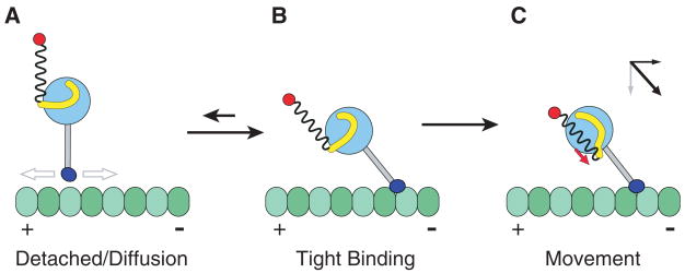
To explain the directionality of dynein, we propose that the AAA+ ring does not elicit a lever-like rotation of the linker domain perpendicular to the stalk (as in Fig. 3B); rather, the force vector of the linker domain’s conformational change is directed parallel to an angled stalk (compare Fig. 4, B and C). This would explain why a rotation of the head around the stalk axis (Fig. 3) does not affect the direction of movement, because the net force vector would still remain parallel to the tilted stalk.
Fig. 4.
Model for directional movement of dynein. (A) After release from the microtubule, the dynein is in a preconformational change (power stroke) state, with the linker domain (yellow) docked on the AAA+ domain (light blue circle) somewhat removed from the base of the stalk (gray). The rest of the dynein tail domain is represented as a loose spring attached to a cargo (red). The dynein MTBD (dark blue) is diffusing to a new site on the microtubule. (B) The MTBD preferentially enters a tightly bound state after binding toward the minus end, with the stalk at an angle. (C) An ATP-driven conformational change in the linker domain produces motion whose main vector directional component is parallel to the direction of the stalk (red arrow). The angle of the stalk thus converts this tension generated by the AAA+ domain into a displacement toward the minus end of the microtubule (as shown by the vector diagram), regardless of the orientation of the AAA+ ring.
This model makes the prediction that the stalk is tilted (extending from the AAA+ ring toward the minus end, as in Fig. 4B) at the time when a productive power stroke occurs. The MTBD may preferentially bind to the microtubule at such an angle, as suggested by our cryo-EM map (Fig. 2B) and a recent reconstruction of a whole axonemal dynein in its pre–power stroke state (19). Alternatively, the MTBD may rebind to the microtubule at various angles, but respond to a power stroke differently depending on its angle of attachment. A force-producing conformational change would produce a productive, minus end–directed displacement of the cargo if the stalk were pointing toward the minus end (e.g., Fig. 4C), whereas the MTBD would release if the stalk were pointing in the opposite direction (18, 20). Further work will be needed to define the orientation of the stalk at different stages of the motility cycle and to learn how dynein might be able to reverse its direction of motion, as has been reported for a mammalian dynein (21).
The model for dynein motility presented here (Fig. 4) differs from the swinging lever arm model developed for myosin and kinesin (22). The dynein stalk does not serve as a rigid lever, as proposed elsewhere (23), but rather acts as a tether that allows the detached MTBD to explore a range of potential microtubule-binding sites and transmit tension between the AAA+ ring and the MTBD. The large AAA+ ring and its associated linker domain undergo ATP-dependent conformational changes (8, 9) that pull along the stalk axis. This is consistent with the known actions of other AAA+ proteins (24) and the previous proposal that dynein acts as a winch (8). And it is the MTBD—one of the smallest elements of the large dynein motor protein—that governs the directionality of the motor.
Supplementary Material
Footnotes
Supporting Online Material www.sciencemag.org/cgi/content/full/322/5908/1691/DC1
Materials and Methods
Tables S1 to S3
Figs. S1 to S7
Movies S1 to S4
References
References and Notes
- 1.Gibbons IR. Cell Motil Cytoskeleton. 1995;32:136. doi: 10.1002/cm.970320214. [DOI] [PubMed] [Google Scholar]
- 2.Howell BJ, et al. J Cell Biol. 2001;155:1159. doi: 10.1083/jcb.200105093. [DOI] [PMC free article] [PubMed] [Google Scholar]
- 3.Vaughan KT. Biochim Biophys Acta. 2005;1744:316. doi: 10.1016/j.bbamcr.2005.05.001. [DOI] [PubMed] [Google Scholar]
- 4.Vallee RB, et al. J Neurobiol. 2004;58:189. doi: 10.1002/neu.10314. [DOI] [PubMed] [Google Scholar]
- 5.Zariwala MA, et al. Annu Rev Physiol. 2007;69:423. doi: 10.1146/annurev.physiol.69.040705.141301. [DOI] [PubMed] [Google Scholar]
- 6.Hafezparast M, et al. Science. 2003;300:808. doi: 10.1126/science.1083129. [DOI] [PubMed] [Google Scholar]
- 7.Zuccarello D, et al. Hum Reprod. 2008;23:1957. doi: 10.1093/humrep/den193. [DOI] [PubMed] [Google Scholar]
- 8.Burgess SA, et al. Nature. 2003;421:715. doi: 10.1038/nature01377. [DOI] [PubMed] [Google Scholar]
- 9.Kon T, et al. Nat Struct Mol Biol. 2005;12:513. doi: 10.1038/nsmb930. [DOI] [PubMed] [Google Scholar]
- 10.Gee MA, et al. Nature. 1997;390:636. doi: 10.1038/37663. [DOI] [PubMed] [Google Scholar]
- 11.Gibbons IR, et al. J Biol Chem. 2005;280:23960. doi: 10.1074/jbc.M501636200. [DOI] [PMC free article] [PubMed] [Google Scholar]
- 12.Woehlke G, et al. Cell. 1997;90:207. doi: 10.1016/s0092-8674(00)80329-3. [DOI] [PubMed] [Google Scholar]
- 13.Koonce MP, Tikhonenko I. Mol Biol Cell. 2000;11:523. doi: 10.1091/mbc.11.2.523. [DOI] [PMC free article] [PubMed] [Google Scholar]
- 14.Mizuno N, et al. EMBO J. 2004;23:2459. doi: 10.1038/sj.emboj.7600240. [DOI] [PMC free article] [PubMed] [Google Scholar]
- 15.Kikkawa M, Hirokawa N. EMBO J. 2006;25:4187. doi: 10.1038/sj.emboj.7601299. [DOI] [PMC free article] [PubMed] [Google Scholar]
- 16.Sindelar CV, Downing KH. J Cell Biol. 2007;177:377. doi: 10.1083/jcb.200612090. [DOI] [PMC free article] [PubMed] [Google Scholar]
- 17.Hulko M, et al. Cell. 2006;126:929. doi: 10.1016/j.cell.2006.06.058. [DOI] [PubMed] [Google Scholar]
- 18.Reck-Peterson SL, et al. Cell. 2006;126:335. doi: 10.1016/j.cell.2006.05.046. [DOI] [PMC free article] [PubMed] [Google Scholar]
- 19.Oda T, et al. J Cell Biol. 2007;177:243. doi: 10.1083/jcb.200609038. [DOI] [PMC free article] [PubMed] [Google Scholar]
- 20.Gennerich A, et al. Cell. 2007;131:952. doi: 10.1016/j.cell.2007.10.016. [DOI] [PMC free article] [PubMed] [Google Scholar]
- 21.Ross JL, et al. Nat Cell Biol. 2006;8:562. doi: 10.1038/ncb1421. [DOI] [PubMed] [Google Scholar]
- 22.Vale RD, Milligan RA. Science. 2000;288:88. doi: 10.1126/science.288.5463.88. [DOI] [PubMed] [Google Scholar]
- 23.Mizuno N, et al. Proc Natl Acad Sci USA. 2007;104:20832. doi: 10.1073/pnas.0710406105. [DOI] [PMC free article] [PubMed] [Google Scholar]
- 24.Tucker PA, Sallai L. Curr Opin Struct Biol. 2007;17:641. doi: 10.1016/j.sbi.2007.09.012. [DOI] [PubMed] [Google Scholar]
- 25.We thank J. Welburn and E. Nogales for advice and equipment; M. Kikkawa for sending his group’s electron density map; and N. Bradshaw, J. Kardon, K. Aathavan, A. Dosé, A. Gennerich, A. Roll-Mecak, and S. Reck-Peterson for critically reading the manuscript. Supported by the Jane Coffin Childs Foundation (A.P.C.); NIH grants GM52468-14 (R.A.M.), P01-AR42895 (R.D.V.) and GM30401-29 (I.R.G.)]; the Agouron Institute (A.P.C.); the Leukemia and Lymphoma Society (A.P.C.); and the Howard Hughes Medical Institute. Crystallography data were collected at beamline 8.3.1 of the Advanced Light Source at Lawrence Berkeley National Laboratory. The atomic coordinates and structure factors have been deposited in the Protein Data Bank (code 3ERR). Cryo-EM data were collected in part at the National Resource for Automated Molecular Microscopy at the Scripps Research Institute (NIH P41 RR-17573). Maps were deposited at the EMDataBank (EMD-1581).
Associated Data
This section collects any data citations, data availability statements, or supplementary materials included in this article.


