Abstract
This paper discusses pediatric image quality and radiation dose considerations in state-of-the-art fluoroscopic imaging equipment. Although most fluoroscopes are capable of automatically providing good image quality on infants, toddlers, and small children, excessive radiation dose levels can result from design deficiencies of the imaging device or inappropriate configuration of the equipment’s capabilities when imaging small body parts. Important design features and setup choices at installation and during the clinical use of the imaging device can improve image quality and reduce radiation exposure levels in pediatric patients. Pediatric radiologists and cardiologists, with the help of medical physicists, need to understand the issues involved in creating good image quality at reasonable pediatric patient doses. The control of radiographic technique factors by the generator of the imaging device must provide a large dynamic range of mAs values per exposure pulse during both fluoroscopy and image recording as a function of patient girth, which is the thickness of the patient in the posterior–anterior projection at the umbilicus (less than 10 cm to greater than 30 cm). The range of pulse widths must be limited to less than 10 ms in children to properly freeze patient motion. Variable rate pulsed fluoroscopy can be leveraged to reduce radiation dose to the patient and improve image quality. Three focal spots with nominal sizes of 0.3 mm to 1 mm are necessary on the pediatric unit. A second, lateral imaging plane might be necessary because of the child’s limited tolerance of contrast medium. Spectral and spatial beam shaping can improve image quality while reducing the radiation dose. Finally, the level of entrance exposure to the image receptor of the fluoroscope as a function of operator choices, of added filter thickness, of selected pulse rate, of the selected field-of-view and of the patient girth all must be addressed at installation.
Keywords: Radiation exposure, Fluoroscopic equipment, Equipment settings
Introduction
This paper discusses setup choices at installation and operator choices during the routine use of fluoroscopic equipment that improve image quality and reduce radiation exposure levels when imaging pediatric patients. Although most state-of-the-art equipment provides good image quality in small children, ‘out of the box– excessive radiation dose levels can result from design deficiencies. A survey at six institutions [1] found high-level-control fluoroscopy exposure rates to range from 21 R/min to 93 R/min! Pediatric interventionalists, with the help of medical physicists, must purchase imaging equipment designed to provide good image quality at reasonable pediatric patient doses and must understand the operational steps required to achieve these two goals. Until recently, manufacturers have been reluctant to design equipment specifically for pediatric applications. Any equipment design changes that improve pediatric imaging must not compromise adult imaging on the same machine.
Image quality, patient dose, and pediatric patient considerations
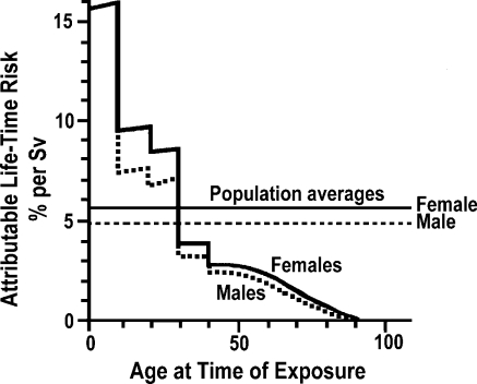
Children are not small adults. First, their disease states differ from those of adults, which might lead to multiple interventions in the imaging room. For example, neonates and infants in the interventional suite suffer from a large variety of congenital heart and/or vascular defects or diseases [2] as opposed to coronary artery disease common in adults. These complex pediatric conditions can require up to ten cardiac catheterizations to manage the disease prior to the patient reaching adulthood [2]! Second, children compared to adults are approximately ten times more sensitive to radiation exposure, as illustrated in Fig. 1 [3]. This figure shows that the lifetime risk of a radiation-induced cancer from 1 Sv of dose during the first decade of life in a child is about 15%, while the risk is approximately 2% in a middle-age adult [3]. This underscores the importance of minimizing the patient radiation dose associated with each study, especially in light of recently published data on the cumulative effects of radiation damage to the skin [4, 5].
Fig. 1.
Attributable lifetime risk of cancer as a function of age for a single whole-body radiation dose of 1 Sv. Children are believed to be approximately ten times more radiosensitive than adults (reprinted with permission from Hall EJ [3])
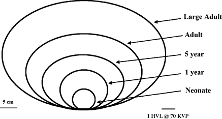
The small size of a neonate or infant relative to an adult demands a large dynamic range of radiologic technique factors. A neonate has a posterior–anterior (PA) girth of about 6 cm, while a large adult can have a PA girth of more than 30 cm [6], as illustrated in Fig. 2. If the half-value layer (HVL) of tissue is assumed to be approximately 3 cm at 70 kVp for imaging equipment with standard total filtration, this range of patient sizes approximates nine HVLs. This requires a dynamic range of mAs values per pulse of radiation during either image recording or pulsed fluoroscopy of 512 to maintain a constant kVp.
Fig. 2.
The PA diameter through the patient’s thorax ranges from 6 cm to 32 cm as a function of age. Because neonates and infants younger than 1 year are ‘barrel-chested– their PA and LAT projections are approximately equal
Image quality must be tightly controlled in infants and small children to obtain clinically useful images. First, the image receptor must provide excellent high-contrast resolution to image the significantly smaller anatomy of an infant and the smaller devices and hardware used by the interventionalist. Second, motion unsharpness must be controlled by pulsed radiation, both during fluoroscopy and the recording of images. Although 8 ms is a reasonable maximum setting for adults (compromise between unsharpness and the need for more X-rays to penetrate a large path length), in small children this value should not exceed 4– ms.
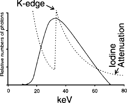
Introduction of iodinated contrast medium, iodine, into the pediatric patient to create subject contrast must be carefully managed. Subject contrast created by iodine is a function of the concentration of the iodine in the vessel and the diameter of the vessel [7]. First, the smaller diameters of the child’s vessels require higher concentrations of contrast medium to achieve the same subject contrast created by larger vessels. Second, the total volume of injected iodine per patient is limited because of the toxicity of the contrast agent (4– cm3/kg of 320–50 mg/cm3 iodine) [2]. Because at least 1 cm3/kg of contrast medium is required to inject a chamber of the heart or great vessel in the pediatric catheterization laboratory, the entire examination might be limited to approximately half a dozen injections. These concerns require careful matching of the effective energy of the X-ray beam, approximately 70 kVp, to the K-edge of iodine, as illustrated in Fig. 3. Fortunately, the small mass of the child and the small field-of-view (FoV) or area of the X-ray field in pediatric imaging result in less scatter radiation and its masking of limited subject contrast.
Fig. 3.
Iodine attenuation vs. 70 kVp X-ray beam spectrum with 3 mm aluminum total filtration. The effective energy of the X-ray beam spectrum, about 30 keV, is well-matched to the 33 keV K-edge of iodine. This matching increases the radiopacity of an iodine-filled vessel (reprinted with permission from Philips Medical Systems [22])
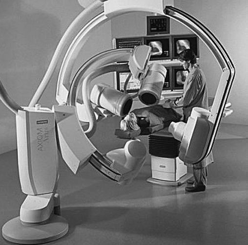
Because the number of iodine injections during complex interventional studies is severely limited in the child, many pediatric interventional laboratories are equipped for two imaging planes that allow the doubling of recorded information per iodine injection. Figure 4 illustrates a representative biplane setup. Each X-ray tube and image receptor is mounted on opposite ends of a large C-arm, which is either ceiling-suspended on a set of rails or floor-mounted. The C-arm rotates on its arc to provide either lateral or cranial–caudal angulation relative to the patient, depending on the positioning of the C-arm, which can be controlled by the operator. Each of the two imaging planes shares the same isocenter, the point in space about which each imaging plane rotates. Although the focal spot to isocenter distance is fixed, the image receptor to isocenter distance can be adjusted by the operator. State-of-the-art units provide preprogrammed positioning of both planes at the push of a button to facilitate reproducible positioning of the stands without exposing the patient to additional radiation.
Fig. 4.
A representative biplane catheterization laboratory setup. Each plane of imaging equipment can be independently rotated laterally and/or in the cranial–caudal direction. The elevating table with a float top allows the patient anatomy of interest to be placed at the isocenter, the common point about which both imaging planes rotate
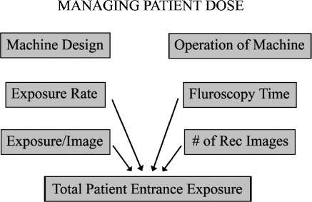
As illustrated in Fig. 5, total radiation exposure of the patient can be reduced by either modifying the fluoroscope to reduce the radiation exposure produced by the machine to create each image or by modifying the protocol of the examination to reduce the number of images created. Both approaches must be exploited to minimize pediatric radiation dose during fluoroscopic examinations.
Fig. 5.
The managing of patient radiation dose involves both the equipment design, which determines the amount of radiation required per image, and the control of the image device by the operator, who determines the total number of images created during the procedure
Generator control of radiologic technique factors
Pulse width and rate of variable rate pulsed fluoroscopy or recording of images
Table 1 lists the range of radiologic technique factors required on an X-ray generator suitable for either pediatric or adult fluoroscopic imaging. Any and all pediatric fluoroscopy, using mobile C-arms to tilt-table conventional fluoroscopes to complex biplane interventional procedure rooms, should be performed with variable rate pulsed fluoroscopy. The pulse width (time the X-ray beam is on for each image) should not exceed 5 ms in small children and 8 ms in adults, to adequately freeze patient motion and reduce motion unsharpness. Alternating pulsed fluoroscopy is mandatory in the biplane interventional laboratory to prevent scatter generated from the lateral plane’s primary beam from degrading subject contrast during recording in the frontal plane and vice versa. The ability to reduce the pulse rate (the number of fluoroscopic images created per unit time) to less than 30 pulses per second (p/s), i.e. 15 and 7.5 p/s for interventional studies and 8, 4, 2 and 1 p/s for fluoroscopic studies in the GI/GU examination room, makes a significant contribution to patient dose reduction [8–10] with only small degradation to image quality because of loss of temporal resolution, if equipment is set up [11] and used properly. The appropriate pulse rate for each segment of a procedure is a function of the operator’s ability to deal with the loss of temporal resolution and the imaging challenge of that segment of the study. In general, cardiac studies in children require higher pulse rates than those in adults because of the faster heart rate of children. The pulse widths listed in Table 1 in the last column for non-cardiac image recording must be significantly increased to deliver the significantly higher radiation dose associated with a recorded digital subtraction angiography (DSA) image.
Table 1.
Required radiologic technique factor ranges
| Parameter | Operational mode | |||
|---|---|---|---|---|
| Fluoroscopy | Image recording | |||
| Pulsed GI/GU | Pulsed interventional | Cardiac | Non-cardiac | |
| Pulse width (ms) | ||||
| Maximum adults | 8 | 8 | 8 | 50 |
| Maximum pediatrics | 5 | 5 | 5 | 20 |
| Optimum pediatrics | 4 | 4 | 4 | 10 |
| Pulse rate (pulses/s) | 1, 2, 4, 8 | 7.5, 15, 30 | 7.5, 15, 30 | 1, 2, 3, 4, 6 |
| High voltage settings (kVp) | ||||
| Optimum/standard filter | 70 | 70 | 70 | 70 |
| Minimum/standard filter | 60 | 60 | 60 | 60 |
| Maximum/standard filter | 120 | 120 | 120 | 120 |
| Optimum/spectral filter | (filter thickness dependent; 50–0 kVp) | |||
| Tube current (mA) | ||||
| Minimum | 10 | 10 | 100 | 100 |
| Maximum | 100 | 100 | 1000 | 1000 |
High voltage
As illustrated in Fig. 3, 70 kVp results in an effective energy reasonably matched to the K-edge of iodine, provided standard added filtration is used, of about 3 mm of equivalent aluminum filtration. Because X-ray tubes do not have sufficient heat loading to allow penetration of large adults at 70 kVp, a maximum kVp of 110 or 120 is necessary. When imaging infants or small children, the tube current must be reduced to prevent the reduction of the kVp below 60 to avoid excessive radiation doses to the skin. As discussed below, spectral filtering, available on most state-of-the-art equipment, reduces the optimum high voltage to between 50 kVp and 65 kVp, depending on the thickness of the added filter.
Tube current
Large adults require the maximum tube current allowed by the heat loading limitations of the X-ray tube to minimize the required kVp during image recording techniques. An X-ray tube with a 70–0 kW rating can produce up to 1000 mA. To prevent the reduction of kVp below 60 during image recording of an infant, the tube current should not exceed 100 mA. The correct tube current during pulsed fluoroscopy of the infant and adult should not exceed 10 mA and 100 mA, respectively. The 10 mA is sufficient to penetrate the small patient and allows the use of a 0.3-mm focal spot, improving spatial resolution. The 100 mA for fluoroscopy of larger patients allows the use of the standard 0.5-mm to 0.6-mm focal spot.
Hierarchy of adjustment of radiologic factors
The order of sequence used by the generator when adjusting the kVp, mA, and pulse width within the ranges listed in Table 1 to maintain the appropriate entrance exposure at the image receptor (EEIR) is critical to minimizing patient entrance dose and maximizing image quality. The variation in path length of the X-rays as a function of patient size and the angle of projection through the patient, the variation of contrast agent present, the absence or presence of air, and the mode of operation (fluoroscopy or recording of images) all require a generator that can quickly and effectively adjust the correct radiologic factor to produce more or less radiation output over an extremely large dynamic range. The correct radiologic factor to change at any given point in time is the factor that least diminishes image quality.
Some manufacturers have made strides recently to better optimize the hierarchical control of radiologic factors for pediatric imaging over the ranges suggested in Table 1. Too many of the vendors–flagship units, however, still do not provide small enough pulse widths to properly freeze pediatric motion. Too many of these units do a good job of increasing tube current to its maximum value for large patients but fail to properly reduce the tube current to a low enough value for the smallest pediatric patients, resulting in needlessly elevated radiation dose.
All of these deficiencies could be corrected by providing the dynamic ranges listed in Table 1 and by using the following scheme in modulating these factors. The initial factors should be the optimum values listed in Table 1. If the image is too bright:
The tube current should be modulated to its minimum value
The pulse width should be modulated to its minimum value and finally
The high voltage should be reduced to provide the correct EEIR.
If the image is not bright enough:
The tube current should be modulated to its maximum value
The pulse width should be modulated to its maximum value and finally
The high voltage should be increased to provide the correct EEIR.
During successive initiations of fluoroscopy after the first initiation, the factors should begin at the final setting of the previous initiation. This should continue until an image recording acquisition is made, after which the factors during the next fluoroscopy should revert back to the optimum values listed in Table 1 to restart the sequence. The above scheme is appropriate for either image recording or pulsed fluoroscopy and should be completely automatic.
Today, no manufacturers–state-of-the-art units automatically provide the above flexibility for the smallest patients. Some allow the clever clinical user to exploit anatomical programming capabilities of the generator to properly image the entire dynamic range of pediatric patients. Multiple programs for each body part are created; each program selects imaging parameters that work well for a limited range of pediatric patient sizes, e.g., neonates to 1-year-olds, 1- to 5-year-olds, etc. With equipment that is as little as a couple years old, optimization of both pediatric image quality and radiation dose will probably be compromised.
X-ray tube assembly
The following design considerations are important for pediatric imaging with respect to the X-ray tube assembly:
Three focal spot sizes
Large kW rating and cooling rate
Spatial beam shaping
Spectral beam shaping
Only two of the large manufacturers can provide all of these features for both cardiac and non-cardiac interventional imaging. No manufacturer provides a triple focal spot tube for a conventional fluoroscopic tilt table system.
The triple focus X-ray tube (nominal focal spot sizes of 0.3 mm, 0.6 mm, and 1 mm) provides maximum flexibility for a unit that must perform both adult and pediatric imaging. The large, medium, and small focal spots, respectively, provide the 1000 mA, 350 mA, and 100 mA necessary for imaging adults, 5- to 15-year-olds, and younger than 5-year-olds. Either the small or medium focal spot is the appropriate choice for pulsed fluoroscopy, depending on the size of the patient.
If the grid of the imaging device can be removed, the 0.3-mm focal spot allows use of geometric magnification up to a factor of 1.6–.8 for small children and infants. This geometric magnification provides better image quality for small anatomical details and provides better accessibility to the patient, as illustrated in Fig. 6. This setup also can reduce the patient entrance skin dose. The increase in the source to image receptor distance (SID) from 85 cm to 125 cm approximately doubles the patient entrance exposure. The removal of the grid and its associated Bucky factor decreases the patient entrance exposure by a factor of about 1.5. The switch to the 23-cm FoV of the image receptor instead of the 11.5-cm FoV decreases the EEIR by a factor of 2 if not 4 on older units. Therefore, during geometric magnification techniques, the patient entrance exposure should be about 33% to 66% of the entrance exposure with standard geometry.
Fig. 6.
Drawing of the geometry of a small child relative to the focal spot and image receptor. a Magnification factor of 1.1 for the midline of the patient’s thorax. b Magnification factor of 1.6 provides better access to the small patient (reprinted with permission from RSNA [44])
Because the modulation transfer function (MTF, measure of resolution) of the image receptor increases while the focal spot MTF decreases with an increase in geometric magnification, the magnification factor at which the two MTF values are equal provides the best overall image quality.
 |
(1) |
 |
(2) |
 |
(3) |
MTFf and MTFr are for the focal spot and image receptor, respectively, m is the magnification in the image, f is the focal spot actual size in millimeters (assumed to be 1.8 times larger than the nominal size), and D is the FoV of the image receptor in millimeters.
Image resolution can be optimized by placing the anatomy of interest at the isocenter and adjusting the SID to provide the optimum geometric magnification listed in Table 2, which is determined by the focal spot size and by the FoV of the image receptor. Equations 1, 2 and 3 were used to calculate the values in Table 2. Because the variable SID on most manufacturers–stands is limited to the 85-cm to 125-cm range, one can set up magnification factors from 1.2 to 1.6 on small patients located at the isocenter. Therefore, the limiting resolution is never achieved with the largest focal spot on the smaller FoVs. Likewise, a large geometric magnification factor is required with the largest FoV and smallest focal spot to achieve the limiting resolution. As one would expect, the best image quality is achieved with the 0.3-mm focal spot and smallest FoV at a reasonable magnification factor of 1.2. Provided the optimum geometric magnification can be achieved, for a given focal spot size, the limiting resolution increases as the FoV decreases. For a given FoV, the limiting resolution increases as the focal spot size decreases.
Table 2.
Limiting resolution as a function of focal spot size, matrix size, and FoV
| Nominal focal spot size (mm) | Matrix size | FoV (mm) | Optimum magnification | Limiting resolution (lp/mm) focal spot or image receptor |
|---|---|---|---|---|
| 0.3 | 1,024 | 370 | 1.66 | 2.3 |
| 0.6 | 1,024 | 370 | 1.33 | 1.8 |
| 1.0 | 1,024 | 370 | 1.20 | 1.7 |
| 0.3 | 1,024 | 230 | 1.42 | 3.2 |
| 0.6 | 1,024 | 230 | 1.21 | 2.7 |
| 1.0 | 1,024 | 230 | 1.12 | 2.5 |
| 0.3 | 1,024 | 115 | 1.21 | 5.3 |
| 0.6 | 1,024 | 115 | 1.10 | 4.8 |
| 1.0 | 1,024 | 115 | 1.06 | 4.7 |
Manufacturers continue to develop larger heat capacity X-ray tubes for imaging larger patients [12]; continuous tube loading rates up to 3 kW now are common. This technology also positively impacts pediatric imaging. These larger tubes should allow a larger dynamic range of tube currents during pulsed fluoroscopy that increases the dynamic range of mAs values per pulse and limits the change of kVp as a function of patient size. These large tubes also provide the opportunity to improve image quality and reduce patient dose by spectral beam shaping.
Spatial beam shaping
Spatial beam shaping involves the change in size or shape of the X-ray beam by the use of standard collimation, equalization filters, or region-of-interest (ROI) filters [13]. Standard beam-defining collimation, both rectangular and circular, is extremely important in reducing integral dose to the small patient because the cross-sectional area of interest of the patient is smaller than the smallest FoV of the image receptor, i.e. 11 cm. More than one manufacturer electronically indicates the location of the collimator blades on the TV monitor. This allows collimator blade adjustment without exposing the patient–an extremely beneficial feature for pediatric imaging.
Equalization filters compensate for attenuation differences between adjacent tissues, e.g., the mediastinum and lung fields, to improve image quality and reduce the integral dose to the patient. Since the heart shadow of a child is small compared to that of an adult, one manufacturer has allowed different shapes and sizes of equalization filters to be mounted within its collimator by the operator.
ROI filters consist of donut-shape attenuators, an open central region surrounded by an attenuator designed to partially attenuate the X-ray beam placed on the face of the collimator [13, 14]. The image quality within the ROI (hole) is actually improved because scatter X-rays in the periphery of the FoV are reduced by the partial attenuation of X-rays [13]. The ROI filter also reduces the integral radiation dose to the patient, since the ROI filter reduces the number of X-rays passing through the patient in the peripheral areas of the FoV [13]. For successful use in pediatric imaging, one needs an array of ROI filters with donut holes of different diameters as a function of patient size. ROI filters can successfully be used when maximum image quality is required near the tip of the catheter, but image quality in the periphery of the FoV is needed for landmark information only.
Spectral beam shaping
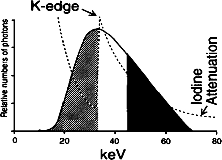
Spectral beam shaping is the change in quality (shape) of the X-ray beam spectrum to match the attenuation curve of iodine-filled blood vessels (Fig. 7, dashed line). Peak attenuation by the iodine–the peak radiopacity of the blood vessels, or maximum subject contrast–occurs at 33–2 keV, a small range of energies just greater than the k shell binding energy of iodine.
Fig. 7.
Low-energy X-rays less than 33 keV (hatched region) are absorbed by the patient’s tissues. The high-energy X-rays greater than 45 keV (black region) contribute to patient dose and generate scattered photons that mask subject contrast. Ideally, both shaded regions of the X-ray beam spectrum should be eliminated (reprinted with permission from RSNA [44])
A typical X-ray beam spectrum corresponding to 70 kVp with standard total filtration of 2.5 mm aluminum is illustrated in Fig. 7 by the solid black curve. The low-energy X-rays, less than 33 keV(the hatched region) are primarily absorbed by the patient’s tissues, increasing dose with minimal contribution to image quality. The high-energy X-rays greater than 42 keV (the black region) contribute patient dose and scattered photons that mask subject contrast. Reports in the literature [15–20] demonstrate that the small range of X-ray energies not shaded in Fig. 7 results in the best balance between patient exposure and contrast in the image. Computer simulation suggests that an appropriate monoenergetic source of X-rays with iodine signal objects and cesium-iodide image receptor could result in a contrast improvement factor of 1.4–.3 [21].
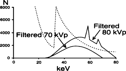
To achieve spectral beam shaping, the X-ray beam must first be heavily filtered to remove the low-energy photons (the hatched region in Fig. 7). Different filter materials and thicknesses have been successfully used [22–33]. Standard equipment would increase the high voltage to 80 kVp in response to the heavy filter (Fig. 8) [22] to compensate for the limited number of X-rays in the heavily filtered 70 kVp beam [28, 34]. This first step eliminates the low-energy photons and reduces the radiation dose to the patient but also reduces subject contrast in the image because of the higher effective energy.
Fig. 8.
The effect on the X-ray beam spectrum of adding copper to the X-ray beam. The generator increases the kVp to compensate for the lost intensity in the X-ray beam. The effective energy increases from approximately 30 keV to approximately 55 keV (reprinted with permission from Philips Medical Systems [22])
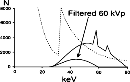
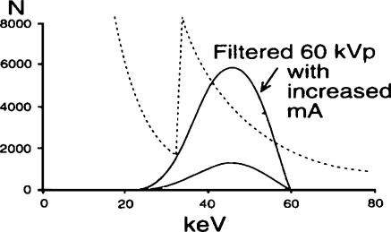
Next, the manufacturer reduces the high voltage within the automatic brightness control algorithm during fluoroscopy or image recording acquisitions in acknowledgment of the following two imaging principles: (1) the kVp should be chosen on the basis of the required contrast of the clinical examination, not on patient size [35], and (2) maximum information content is obtained at a chosen high voltage matched to a specific filtration [18]. Figure 9 shows that a 60-kVp heavily filtered beam eliminates all photons greater than 60 keV [22], but this step alone results in an inadequate X-ray beam intensity. The second change to the automatic brightness control algorithm involves increasing the tube current as illustrated in Fig. 10 [22]. These three steps (added heavy filter, reduced high voltage, and increased tube current) create a pseudomonochromatic beam (33–0 keV), an improvement over the standard spectrum in Fig. 7 with a range of energies from 15 keV to 70 keV.
Fig. 9.
The effect on the X-ray beam spectrum after decreasing the kVp from 80 to 60. The effective energy decreases from 55 keV to 45 keV, but the intensity of the beam, the area under the curve, is too limited because of the increased attenuation of the copper at the low X-ray energy (reprinted with permission from Philips Medical Systems [22])
Fig. 10.
The effect on the X-ray beam spectrum after increasing the tube current by a factor of at least five. The result of heavy filtration, reduced kVp and increased mA is to provide a pseudomonochromatic beam (33–0 keV) in comparison to the spectrum of Fig. 3 (effective energy 15–0 keV) (reprinted with permission from Philips Medical Systems [22])
Ideally, a fluoroscope for pediatric use should have a large anode X-ray tube with a large kW rating that allows the use of a variety of filter thicknesses that are automatically selected as a function of patient thickness during either fluoroscopy or image record modes. The automatically selected kVp and filter thickness should result in subject contrast at least equivalent to that of a 70 kVp X-ray beam with standard added X-ray tube filtration (about 3 mm Al). The manufacturer must resist the temptation to increase the pulse width to values greater than those listed in Table 1 for pediatric imaging (5 ms) to allow the use of a heavier filter for a given patient thickness.
Patient table top extension
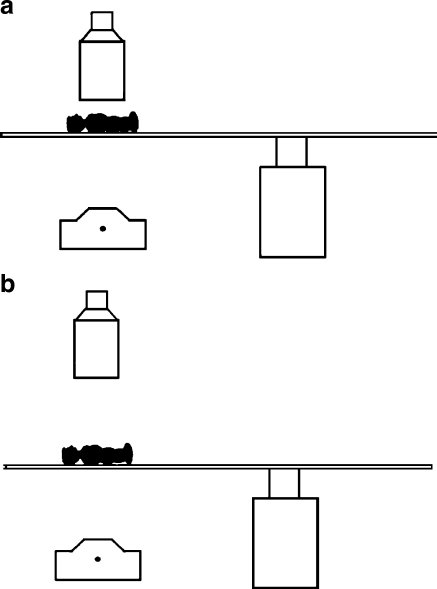
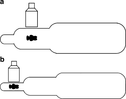
Figure 11 illustrates the shape of a standard table top for adults as viewed from overhead. The torso region is substantially wider than a small child, which introduces geometric magnification if the patient is positioned on the center-line of the table top. If the unit contains a nominal 0.3-mm focal spot and the grid can be removed, this is not an issue. If the grid is fixed or the small focal spot is larger than 0.3 mm, this geometric setup increases patient dose and geometric unsharpness in the image. These problems can be avoided by putting a form-fitted extension constructed of carbon fiber material [36] on the narrow head region of the table top. This extension allows proper positioning of the patient and lateral image receptor as illustrated in Fig. 11. This extension should not be wider than the narrow head region of the standard table top to discourage cantilevering larger patients too far from the pedestal support of the table; these table tops are not designed to support heavy loads concentrated at their head ends. A means of securing the small patient to the narrow table top extension must be provided.
Fig. 11.
Standard table top for adults. a Overhead view with an infant centered on the table top. b Table top with extension constructed of carbon fiber on the narrow head region of the table top, which allows correct positioning of an infant or toddler and lateral image receptor. For safety reasons, this extension should not be wider than the narrow head region of the standard table-top, and a means of securing the patient to the narrow table top must be provided (reprinted with permission from RSNA [44])
Grids
Manufacturers provide grids that are properly designed for the full FoV of the image receptor and an adult-size patient. Because studies of small children use a collimated X-ray beam smaller than the smallest FoV of the image receptor, much less scatter is created. Grid ratios of 10:1 or higher elevate radiation doses of small patients without markedly improving image quality because of the lower levels of scatter [37, 38]. In fact, the grid can effectively be eliminated when imaging small children even if the air gap technique discussed previously is not used [39, 40]. For an interventional unit that performs a significant amount of pediatric imaging, an 8:1 grid ratio is a reasonable compromise. This grid choice will compromise image quality somewhat on large patients, but patient radiation doses will be more reasonable on small patients.
Field-of-view of image receptor
Most manufacturers provide triple field image receptors with a maximum size of 20–3 cm in adult cardiac interventional suites. The largest FoVs currently in vascular interventional suites are 35–0 cm image receptors with four or five selectable FoVs. The most magnified electronic view (smallest FoV), which typically uses 12–5 cm of the image receptor, allows improved viewing of the small structures of infants.
Changes to typical adult image receptor sizes are helpful in pediatric imaging. A 20–3 cm FoV image receptor in the pediatric catheterization laboratory is not large enough to image both lung fields in larger patients who have survived pulmonary artery disease diagnosed and treated since childhood; a 30–5 cm FoV image receptor in the frontal plane of a biplane unit is needed. The compromises associated with a larger FoV in one plane are more limited compound angles of the two planes and more difficult access to the patient. Likewise, the standard 35–0 cm image receptor in the single plane adult vascular laboratory should be reduced to a 30 cm image receptor in the biplane pediatric laboratory. The reduced-size image receptors provide better access to small patients and allow a greater degree of compound angles without collision of the two imaging planes.
Control of image receptor exposure (EEIR)
Optimum entrance exposure to the patient is achieved by maintaining an appropriate exposure to the image receptor for each created image during a variety of operational modes of either fluoroscopy or image recording. Some of this control is provided automatically by properly designed imaging equipment, while intervention by the operator is required to completely optimize patient exposure. The following discusses first operator controls and then automated equipment design features that need to be provided for pediatric imaging.
The operator must judiciously use a number of controls at table side to control patient exposure. First, if anatomical programming capabilities of the machine have been exploited during configuration of the unit at installation to extend the dynamic range of the radiographic technique factors as discussed previously, the operator must ensure the appropriate program is selected at the beginning of the case. Second, operator selectable EEIR values (e.g. low, medium, high; low=0.5×medium=0.25×high) allow the operator to match patient entrance exposure to the particular imaging task [41–43]. Initial catheter placement probably does not require the level of image quality that the final placement of a stent requires. Third, a ‘last-image-hold–feature provides the last fluoroscopic image in a fluoroscopic sequence when the foot pedal is released. This image might allow the operator to reduce fluoroscopy time of the case. Fourth, many units have a ‘fluoroscopy image store mode– which allows a single frame of fluoroscopic video to be ‘grabbed–and stored to disc. Although this image contains more quantum mottle than a standard recorded image, its image quality might be sufficient to avoid the radiation dose of an additional recorded image or sequence of images. Finally, some of the newest equipment provides ‘last-fluoro-loop playback/store– This allows the operator to playback in real time up to 300 fluoroscopic video images from the last fluoroscopic sequence–a tremendous teaching tool in a residency program–or to store this fluoroscopic sequence to disk.
The design of the imaging equipment should control the EEIR each time the operator selects a different FoV of the image receptor. The EEIR is typically proportional to 1/FoV2, 1/FoV, or a constant, depending on equipment design. These designs increase the patient exposure per image fourfold, twofold, and not at all as the FoV is reduced to half of its original size. Because the number of photons absorbed per area at the input receptor is independent of the FoV for a constant EEIR, the total noise in the image is relatively unchanged as a function of FoV. However, because the image might become sharper as the FoV decreases, perceived noise increases despite constant total noise. Therefore, EEIR α 1/FoV is a good choice for pediatric imaging with image intensifiers. It maintains reasonable perceived noise in the image without a larger patient exposure increase associated with EEIR α 1/FoV2. This same logic applies to the design criteria for flat plate image receptors, EEIR α 1/FoV, provided the reduction in FoV also results in a reduction of pixel size within the flat plate receptor. However, when a reduction in FoV with the flat plate receptor does not reduce the pixel size, EEIR α constant, is probably a better design choice for pediatrics.
The EEIR per image should automatically increase, according to Eq. 4, when the operator reduces the pulse rate during pulsed fluoroscopy from 30 pulses per second to 7.5 pulses per second to maintain a constant perceived noise level in the image [11].
 |
(4) |
Perceived noise in the image is a function of the number of images averaged together by the operator’s eye for 0.2 s. At 30 pulses per second the human eye integrates six fluoroscopic images together, reducing the perceived noise, while at 7.5 pulses per second no physiologic integration occurs. Because Eq. 5 applies only to pulse rates resulting in integration of more than one image, the EEIR per pulse as one reduces the pulse rate below 7.5 pulses per second should follow the relationship shown in Eq. 5:
 |
(5) |
Table 3 lists a range of EEIR values for each operating mode of fluoroscopic imaging equipment calibrated for pediatric imaging. These values apply to a nominal 23 cm FoV image receptor with the kVp approximately equal to 80. If standard filtration is present in the beam (2.5 mm to 3 mm aluminum total filtration) the actual EEIR values should fall within the suggested range. If spectral beam filtering is used, the actual EEIR values during fluoroscopy should be double the values in the table to avoid an increase in the perceived noise.
Table 3.
Suggested EEIR values for pediatric fluoroscopic imaging equipment. Values recommended for a 23-cm FoV image receptor, ‘normal–exposure rate, 30 pulses per second during fluoroscopy, at 80 kVp, with standard total filtration of 2.5 mm aluminum. Numbers in the table are in units of air kerma in nGy per image
| Operational mode | EEIR range |
|---|---|
| ‘Low–fluoroscopy | 6–.5 |
| ‘Medium–fluoroscopy | 12–7 |
| ‘High–fluoroscopy | 24–4 |
| Digital angiography | 450–00 |
| Digital subtraction angiography | 4,500–,000 |
| Cardiac digital | 90–30 |
Conclusion
This discussion illustrates that proper imaging of pediatric patients cannot assume that children are small adults. Imaging equipment needs to be specifically designed and configured for children, while the operator must operate the device to exploit these imaging capabilities at appropriate radiation dose levels. The generator must provide a large dynamic range of mAs values per exposure pulse during both fluoroscopy and image recording to minimize the required range of high voltage (control contrast) and duration of pulse widths (control motion unsharpness) as a function of patient girth (less than 10 cm to greater than 30 cm). Three focal spots of the X-ray tube, a lateral imaging plane, spatial and spectral beam shaping, and properly designed control of the EEIR are necessary to optimize pediatric image quality with reduced radiation exposure of the child.
References
- 1.Boone JM, Pfeiffer DE, Strauss KJ, et al (1993) A survey of fluoroscopic exposure rates: AAPM task group II report. Med Phys 20:789–94 [DOI] [PubMed]
- 2.Chung T, Kirks DR (1998) Techniques. In: Kirks DR, Griscom NT (eds) Practical pediatric imaging. Lippincott-Raven, Philadelphia, pp 1–3
- 3.Hall EJ (2002) Lessons we have learned from our children: cancer risks from diagnostic radiology. Pediatr Radiol 32:700–06 [DOI] [PubMed]
- 4.Lichtenstein DA, Klapholz L, Vardy DA, et al (1996) Chronic radiodermatitis following cardiac catheterization. Arch Dermatol 132:663–67 [DOI] [PubMed]
- 5.Shope TB (1996) Radiation-induced skin injuries from fluoroscopy. Radiographics 16:1195–199 [DOI] [PubMed]
- 6.Jones KL (1997) Smith’s recognizable patterns of human malformation, 5th edn. Saunders, Philadelphia
- 7.Kruger RA (1984) Basic concepts of digital subtraction angiography. Hall Medical Publishers, Boston
- 8.Hernandez RJ, Goodsitt MM (1996) Reduction of radiation dose in pediatric patients using pulsed fluoroscopy. AJR 167:1247–253 [DOI] [PubMed]
- 9.Grollman JH Jr, Klosterman H, Herman MW, et al (1972) Dose reduction low pulse-rate fluoroscopy. Radiology 105:293–98 [DOI] [PubMed]
- 10.Grollman JH Jr (1974) Radiation reduction by means of low pulse-rate fluoroscopy during cardiac catheterization and coronary arteriography. Am J Roentgenol Radium Ther Nucl Med 121:636–41 [DOI] [PubMed]
- 11.Aufrichtig R, Xue P, Thomas CW, et al (1994) Perceptual comparison of pulsed and continuous fluoroscopy. Med Phys 21:245–56 [DOI] [PubMed]
- 12.Ammann E, Wiede G (1995) Generators and tubes in interventional radiology. In: Balter S, Shope TB (eds) Physical and technical aspects of angiography and interventional radiology. RSNA Publications, Oak Brook, Ill, pp 59–4
- 13.Rudin S, Bednarek DR (1995) Spatial shaping of the beam: collimation, grids, equalization filters, and region-of-interest fluoroscopy. In: Balter S, Shope TB (eds) Physical and technical aspects of angiography and interventional radiology. RSNA Publications, Oak Brook, Ill, pp 75–5
- 14.Labbe MS, Chiu MY, Rzeszotarski MS, et al (1994) The x-ray fovea, a device for reducing x-ray dose in fluoroscopy. Med Phys 21:471–81 [DOI] [PubMed]
- 15.Atkins HL, Fairchild RG, Robertson JS, et al (1975) Effect of absorption edge filters on diagnostic x-ray spectra. Radiology 115:431–37 [DOI] [PubMed]
- 16.Burgess AE (1981) Contrast effects of a gadolinium filter. Med Phys 8:203–09 [DOI] [PubMed]
- 17.Johnson MA, Burgess AE (1981) Clinical use of a gadolinium filter in pediatric radiography. Pediatr Radiol 10:229–32 [DOI] [PubMed]
- 18.Motz JW, Danos M (1978) Image information content and patient exposure. Med Phys 5:8–2 [DOI] [PubMed]
- 19.Oosterkamp IW (1961) Monochromatic x-rays for medical fluoroscopy and radiography? Medicamundi 7:68–7 [PubMed]
- 20.Villagran JE, Hobbs BB, Taylor KW (1978) Reduction of patient exposure by use of heavy elements as radiation filters in diagnostic radiology. Radiology 127:249–54 [DOI] [PubMed]
- 21.Boone JM, Seibert JA (1994) A comparison of mono- and poly-energetic x-ray beam performance for radiographic and fluoroscopic imaging. Med Phys 21:1853–863 [DOI] [PubMed]
- 22.Balter S (1995) Managing radiation in the fluoroscopic environment. Philips Medical Systems 4522 982 4900:1–5
- 23.Gagne RM, Quinn PW (1995) X-ray spectral considerations in fluoroscopy. In: Balter S, Shope TB (eds) Physical and technical aspects of angiography and interventional radiology. RSNA Publications, Oak Brook, Ill, pp 49–8
- 24.den Boer A, de Feyter PJ, Hummel WA, et al (1994) Reduction of radiation exposure while maintaining high-quality fluoroscopic images during interventional cardiology using novel x-ray tube technology with extra beam filtering. Circulation 89:2710–714 [DOI] [PubMed]
- 25.Thierens H, Kunnen M, Van der Plaetsen A, et al (1991) Evaluation of the use of a niobium filter for patient dose reduction in chest radiography. Br J Radiol 64:334–40 [DOI] [PubMed]
- 26.Rossi RP, Harnisch B, Hendee WR (1982) Reduction of radiation exposure in radiography of the chest. Radiology 144:909–14 [DOI] [PubMed]
- 27.Thorsen F, Mehus A, Nordanger J (1990) The use of copper and niobium filters in diagnostic x-ray equipment. A comparison of dose reduction, tube loading and picture quality. Tidsskr Nor Laegeforen 110:2878–880 [PubMed]
- 28.Gagne RM, Quinn PW, Jennings RJ (1994) Comparison of beam-hardening and K-edge filters for imaging barium and iodine during fluoroscopy. Med Phys 21:107–21 [DOI] [PubMed]
- 29.Wesenberg RL, Amundson GM, Mueller DL, et al (1987) Ultra-low-dose routine pediatric radiography utilizing a rare-earth filter. Can Assoc Radiol J 38:158–64 [PubMed]
- 30.Campbell JM, Kuntzler CM, Nikesch W (1986) Exposure reduction using yttrium filters in a cardiac catheterization unit. Cathet Cardiovasc Diagn 12:202–04 [PubMed]
- 31.Kohn ML, Gooch AW Jr, Keller WS (1988) Filters for radiation reduction: a comparison. Radiology 167:255–57 [DOI] [PubMed]
- 32.Jangland L, Axelsson B (1990) Niobium filters for dose reduction in pediatric radiology. Acta Radiol 31:540–41 [DOI] [PubMed]
- 33.Williamson BD, van Doorn T (1994) The efficacy of K-edge filters in diagnostic radiology. Australas Phys Eng Sci Med 17:162–74 [PubMed]
- 34.Burgess AE (1985) Physical measurements of heavy metal filter performance. Med Phys 12:225–28 [DOI] [PubMed]
- 35.Ort MG, Gregg EC, Pillai KM, et al (1979) Radiographic quality, tube potential, and patient dose. Med Phys 6:134–36 [DOI] [PubMed]
- 36.Hufton AP, Russell JG (1986) The use of carbon fibre material in table tops, cassette fronts and grid covers: magnitude of possible dose reduction. Br J Radiol 59:157–63 [DOI] [PubMed]
- 37.Sandborg M, Dance DR, Carlsson GA, et al (1993) Monte Carlo study of grid performance in diagnostic radiology: factors which affect the selection of tube potential and grid ratio. Br J Radiol 66:1164–176 [DOI] [PubMed]
- 38.McDaniel DL, Cohen G, Wagner LK, et al (1984) Relative dose efficiencies of antiscatter grids and air gaps in pediatric radiography. Med Phys 11:508–12 [DOI] [PubMed]
- 39.Drury P, Robinson A (1980) Fluoroscopy without the grid: a method of reducing the radiation dose. Br J Radiol 53:93–9 [DOI] [PubMed]
- 40.Gray JE, Swee RG (1982) The elimination of grids during intensified fluoroscopy and photofluoro spot imaging. Radiology 144:426–29 [DOI] [PubMed]
- 41.Rossi RP, Wesenberg RL, Hendee WR (1978) A variable aperture fluoroscopic unit for reduced patient exposure. Radiology 129:799–02 [DOI] [PubMed]
- 42.Rudin S, Bednarek DR, Miller JA (1991) Dose reduction during fluoroscopic placement of feeding tubes. Radiology 178:647–51 [DOI] [PubMed]
- 43.Rudin S, Bednarek DR (1992) Minimizing radiation dose to patient and staff during fluoroscopic, nasoenteral tube insertions. Br J Radiol 65:162–66 [DOI] [PubMed]
- 44.Strauss KJ (1998) Cardiac catheterization equipment requirements: pediatric catheterization laboratory considerations. In: Nickoloff EL, Strauss KJ (eds) Cardiac catheterization imaging. RSNA Publications, Oak Brook, Ill, pp 105–19


