Abstract
This paper describes three ways to tune the multipolar surface plasmon resonances of Au pyramidal particles: (1) by varying their thickness; (2) by controlling their relative orientation on a surface; and (3) by changing the refractive index of the surrounding media. We found that as the index of the medium was increased that the plasmon resonances red-shifted linearly from visible to near infrared wavelengths. By screening the different geometric parameters, we found that 25-nm thick pyramids in a tip-up orientation produced the largest refractive index sensitivities.
Noble metal nanoparticles (NPs) support localized surface plasmon (LSP) resonances at visible wavelengths that can be tuned by changing variables such as material, size and shape.1,2 LSP resonances can also be tailored by varying factors such as particle-particle distance and the dielectric environment surrounding the NPs.3,4 The adsorption of biological molecules, such as antibodies and proteins, to a particle with the appropriate surface functionalities increases the local refractive index (n) surrounding the particle, which in turn shifts the LSP resonance wavelength.5-7 The refractive index sensitivity of particles can be quantified by a figure of merit (FOM) value, which is calculated by dividing the slope of the LSP peak shift (Δλ/Δn) by the full-width-at-half-maximum (FWHM) of the peak. Typical values range from 1 to 5.4 for Au and Ag NPs.8
Metal NPs synthesized using chemical methods are typically small (diameters, d < 50 nm) and have symmetric shapes, such as spheres, rods, or cubes.9,10 Because of their size, these NPs only support dipolar LSP resonances that shift linearly as n of the surrounding media increases.6,10 Larger particles, such as spherical Au particles (d > 400 nm), can support higher order plasmon modes, including quadrupoles and octopoles, which also shift linearly and with similar slopes as n changes.11 Other relatively large structures, such as nanofabricated Au pyramids (d = 250-300 nm), can sustain multipolar surface plasmon modes, including quadrupolar12-14 and mixed mode excitations.15,16 For example, a transverse electric (TE)-like mode, where the oscillation was perpendicular to both the polarization and the wavevector of the incident light, was identified in the pyramids.15 Furthermore, the different modes that are preferentially excited gave rise to the orientation dependence of the scattering spectra of Au pyramids.13 Here, we investigated how the thickness, relative orientation, and n can be used to tune the plasmon resonances of Au nanopyramids. The versatility of our top-down method allows us to screen and then to optimize structural parameters (such as diameter and thickness) independently for specific applications, such as sensing.
Au pyramids (d = 300 nm) were fabricated using a large scale nanofabrication procedure called PEEL.12 In brief, Au was deposited onto a Si (100) substrate patterned with an array of pyramidal pits. After the removal of the Au film by etching the sacrificial Cr layer, the substrate was sonicated in a dilute KOH/IPA solution to release the pyramids into an aqueous solution. Au pyramids were then dispersed on indium tin oxide (ITO) substrates (nITO ≈ 1.8) patterned with alignment markers (produced by e-beam deposition of Au through transmission electron microscopy grids) so that scanning electron microscopy images and single particle scattering spectra could be collected from the same particle. The light scattered by individual pyramids was imaged using an inverted optical microscope (Nikon TE2000-U) under a dark field (DF) illumination set-up, collected using a variable numerical aperture objective lens (×100, NA = 0.5 for DF), and analyzed using a spectrometer (Jovin-Yvon TRIAX 550) equipped with a liquid nitrogen cooled imaging CCD detector (Jovin-Yvon Symphony).13 The peak centers were identified at the maximum scattering intensities, and the peak widths were determined by measuring the wavelength where the half-maximum occurred, subtracting the half-max wavelength from the peak center, and doubling the difference. Immersion oils with different indices (n = 1.293, 1.4, 1.5, and 1.6) were used to change the bulk index surrounding the particles. Between measurements under different refractive index conditions, the pyramids on the ITO substrates were washed with ethanol. At least three different pyramids at every thickness and orientation were measured in order to account for slight variations in pyramid structure.
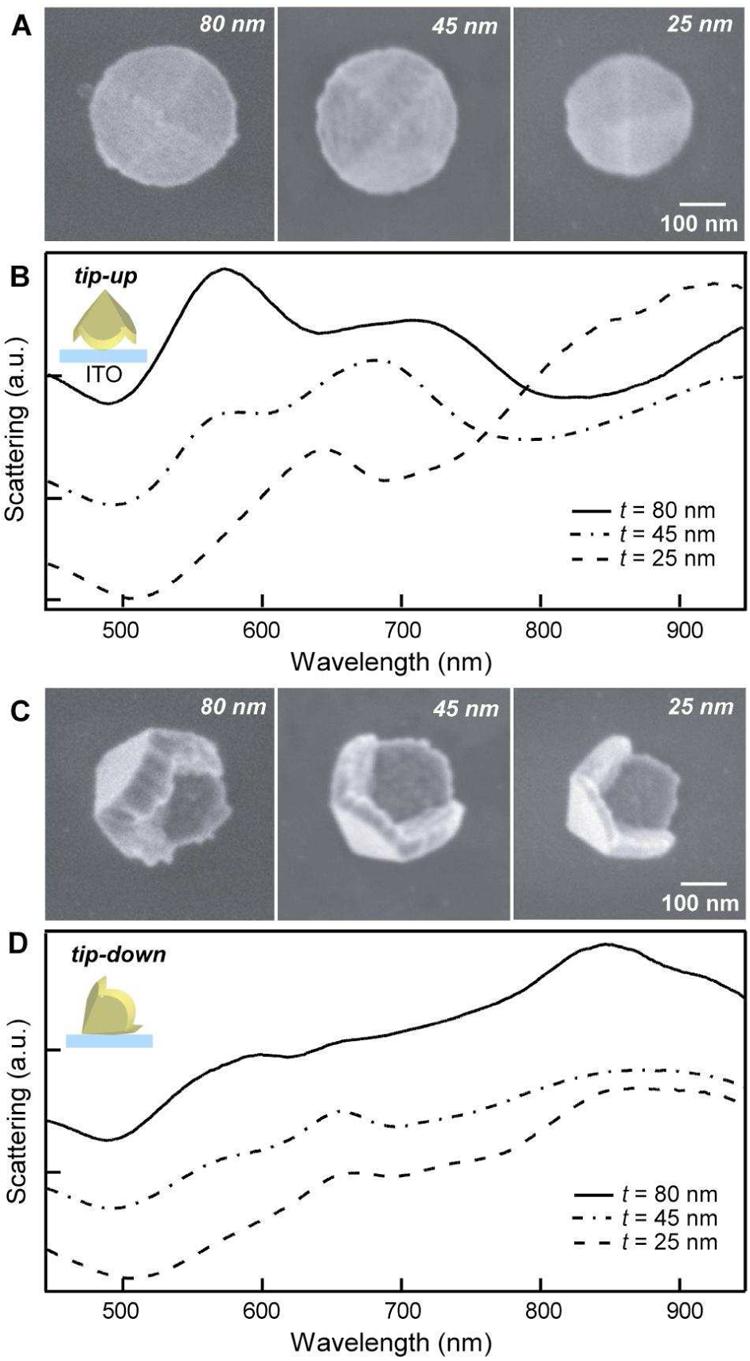
Figure 1 compares SEM and single particle scattering spectra of Au pyramids with three thicknesses (t = 80, 45, and 25 nm). The 25-nm pyramids used in this study were slightly smaller (d = 250 nm) than 45- and 80-nm pyramids (d = 300 nm); their spectra resemble those of 15-nm thick Au pyramids (d = 300 nm).14 Pyramids with their tips pointing away from the substrate (tip-up pyramids) showed strong resonances centered around 600 nm. The intensity of this resonance relative to that at near infrared (NIR, λ > 700 nm) wavelengths increased as the thickness of the pyramids increased. When t was decreased to 25 nm, the 600-nm peak shifted to 650 nm (Fig. 1B). The resonances at 600 nm of tip-down pyramids were weaker than those of tip-up pyramids. The relative intensity of the 600-nm peak increased as the thickness increased, although the increase was smaller than the increase exhibited by tip-up pyramids (Fig. 1D). Scattering spectra of pyramids with their tips in contact with the substrate (tip-down pyramids) were dominated by resonances between 700 - 800 nm. All of these scattering peaks in the spectra represent multipolar (quadrupolar or mixed) resonance modes since dipolar resonances for 300-nm Au pyramids appear between 1000 - 1500 nm.15
Figure 1.

SEM and single particle scattering spectra of 80-nm, 45-nm and 25-nm thick Au pyramids in (A, B) tip-up and (C, D) tip-down orientations (n = 1.293).
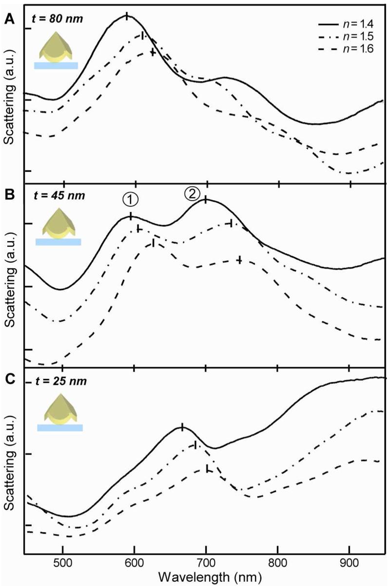
To determine the refractive index sensitivity of Au pyramids in a tip-up orientation, we increased n from 1.293 to 1.6, which resulted in a consistent red-shift of LSP resonances without noticeable changes in the spectral features (Fig. 2). LSP peaks in the short wavelength region for t = 25 nm and t = 80 nm pyramids shifted linearly as n increased, and the slopes Δλ/Δn decreased from 174 to 130 nm/RIU (Table I). This higher index sensitivity for thinner pyramids may arise because a greater fraction of their scattering volume is located near the particle surface compared to thicker pyramids. Thus, they are more affected by small changes in dielectric environment. In the case of t = 45 nm Au pyramids, two resonance peaks were resolved; both red-shifted linearly as n was increased with different slopes (Table I, Δλ/Δn = 143 ± 14 nm for peak 1, and Δλ/Δn = 221 ± 9 nm for peak 2). Spectral features at NIR wavelengths also shifted red systematically, which demonstrates that the resonant peaks of Au pyramids can be tuned across a wide wavelength range.
Figure 2.

Single particle scattering spectra of (A) 80-nm, (B) 45-nm, and (C) 25-nm thick tip-up Au pyramids as a function of refractive index.
Table I.
Refractive index sensitivity of Au nanopyramid surface plasmon scattering peaks.
| Pyramid thickness |
Tip-up | Tip-down | ||||
|---|---|---|---|---|---|---|
| Shift (nm/RIU) | Peak Width (nm) |
FOM | Shift (nm/RIU) |
Peak Width (nm) |
FOM | |
| 25 nm | 174±16 | 125±3 | 1.4±0.1 | 169±14 | 145±17 | 1.2±0.1 |
| 45 nm | 143±14 (peak 1) 221±9 (peak 2) |
84±5 114±28 |
1.7±0.1 2.2±0.5 |
191±15 | 159±6 | 1.2±0.1 |
| 80 nm | 130±6 | 95±8 | 1.4±0.2 | 199±30 | 140±8 | 1.4±0.2 |
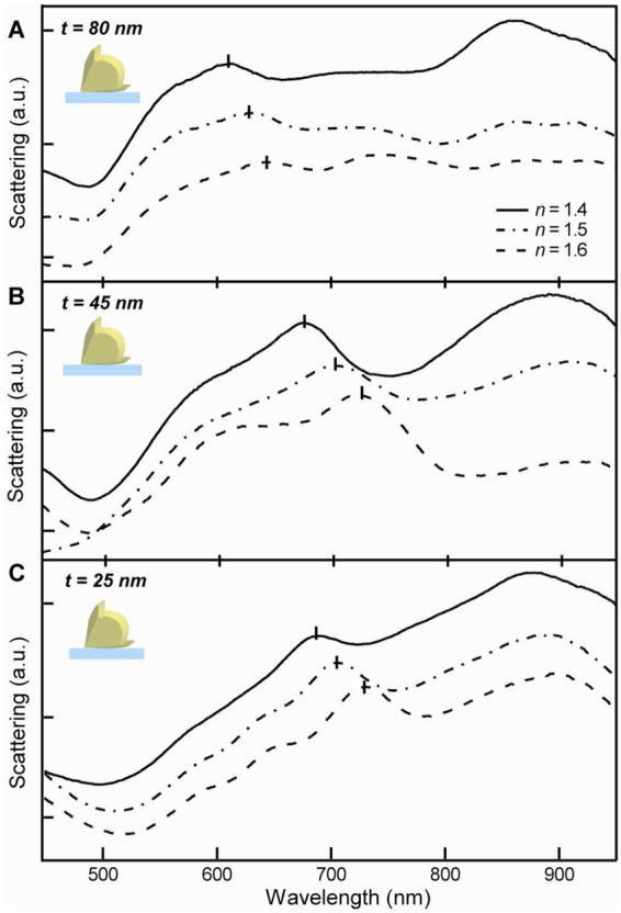
We also examined the sensitivity of tip-down Au pyramids with the same thicknesses to changes in the bulk dielectric environment (Fig. 3). Several LSP modes could be resolved, although some appeared as shoulders adjacent to other plasmon resonances. There were many distinct differences between tip-down and tip-up spectra as a function of thickness: (1) The LSP resonance peaks from t = 80 nm tip-down pyramids were broader than those in the tip-up pyramid spectra; (2) only one well-defined resonance was observed at shorter wavelengths for t = 45 nm tip-down pyramids; and (3) on average, the peaks from t = 25 nm tip-down pyramids were red-shifted compared to tip-up pyramids under the same index conditions. In observations (2) and (3), substrate effects play an important role. For example, peak 1 (t = 45 nm) in the tip-up case may now be observed as a shoulder in the tip-down case because of contact with the n = 1.8 ITO substrate. Also, for t = 25 nm tip-down pyramids, the resonances occurred at longer wavelengths because an entire pyramidal face was in contact with the ITO. Interestingly, the absolute peak shifts as a function of index for tip-down pyramids were similar to or slightly greater than those of pyramids in the tip-up orientation. The broadness of the peaks, however, decreased the FOM values and overall refractive index sensitivities (Table I). Although tip-up Au pyramids (t = 45 nm) exhibited the largest FOM values (1.7 and 2.2), the peaks are located close to each other and are difficult to resolve. Therefore, taking a conservative interpretation and considering a single resonance, we assign the highest FOM (1.4) to the thinnest (t = 25 nm) tip-up pyramids, which is comparable to that of Au spheres, Au nanoshells, and Ag triangles.8
Figure 3.

Single particle scattering spectra of (A) 80-nm, (B) 45-nm, and (C) 25-nm thick tip-down Au pyramids as a function of refractive index.
Substrate effects can also explain why thin Au pyramids in a tip-up orientation exhibited the highest sensitivities. As discussed previously, the slopes Δλ/Δn increased as the thicknesses decreased. Tip-down pyramids, however, showed the opposite trend: the thinnest (t = 25 nm) pyramids exhibited the smallest slopes, and the slopes from t = 45 nm and t = 80 nm pyramids were similar. The thinnest tip-down pyramids were more adversely affected by the substrate because one out of four outer faces was in contact with the ITO. If the corresponding interior face of the thinnest pyramid cannot interact with the surrounding media because the entire scattering volume is affected by the substrate, then only six faces are available to interact with the local environment. Based on a geometric argument and the prediction that the inner and outer faces do not interact much in thicker pyramids,15 thicker tip-down pyramids have seven out of eight sides that can interact with the media. This increased (17%) effective surface area is in good agreement with the measured slopes (169 vs 199 nm/RIU). A similar adverse effect of substrates on refractive index sensitivity was observed when metal nanodisks were placed close to the substrate.17 In contrast, the contact area between tip-up pyramids and the substrate is much less than the geometric area πdt because the actual contact between the pyramid and substrate is a sharp edge around the base of a pyramid (Fig. 1, insets).12,16
In summary, we have systematically studied the effects of thickness, relative orientation, and n on the multipolar surface plasmon resonances of Au nanopyramids. Thus, we identified two design rules for maximizing the sensitivity of these particles: thin thicknesses and tip-up orientations. We found that 25-nm thick, tip-up Au pyramids showed the highest sensitivity because a larger portion of the scattering volume was near the surface, and there was minimal interaction with the substrate in such a geometry. These results can assist in tailoring the structure of broad classes of noble metal particles for chemical and biological sensing applications.
ACKNOWLEDGMENTS
This work was supported in part by the Center of Cancer Nanotechnology Excellence initiative of the NIH National Cancer Institute under Award Number U54CA119341, the NSF MRSEC program at Northwestern University (DMR-0520513), the David and Lucile Packard Foundation, and the NIH Director's Pioneer Award (DP1OD003899). This work used the NUANCE Center facilities, which are supported by NSF-MRSEC, NSF-NSEC and the Keck Foundation.
REFERENCES
- 1.Jain PK, Lee KS, El-Sayed IH, El-Sayed MA. J. Phys. Chem. B. 2006;110:7238. doi: 10.1021/jp057170o. [DOI] [PubMed] [Google Scholar]
- 2.Yguerabide J, Yguerabide EE. Anal. Biochem. 1998;262:137. doi: 10.1006/abio.1998.2759. [DOI] [PubMed] [Google Scholar]
- 3.Elghanian R, Storhoff JJ, Mucic RC, Letsinger RL, Mirkin CA. Science. 1997;277:1078. doi: 10.1126/science.277.5329.1078. [DOI] [PubMed] [Google Scholar]
- 4.Haes AJ, Haynes CL, McFarland AD, Schatz GC, van Duyne RP, Zou S. MRS Bull. 2005;30:368. [Google Scholar]
- 5.Willets KA, Van Duyne RP. Ann. Rev. Phys. Chem. 2006;58:267. doi: 10.1146/annurev.physchem.58.032806.104607. [DOI] [PubMed] [Google Scholar]
- 6.Haes AJ, Chang L, Klein WL, Van Duyne RP. J. Am. Chem. Soc. 2005;127:2264. doi: 10.1021/ja044087q. [DOI] [PubMed] [Google Scholar]
- 7.Anker JN, Hall WP, Lyandres O, Shah NC, Zhao H, Van Duyne RP. Nature Mater. 2008;7:442. doi: 10.1038/nmat2162. [DOI] [PubMed] [Google Scholar]
- 8.Liao H, Nehl CL, Hafner JH. Nanomedicine. 2006;1:201. doi: 10.2217/17435889.1.2.201. [DOI] [PubMed] [Google Scholar]
- 9.Xia Y, Halas NJ. MRS Bull. 2005;30:338. [Google Scholar]
- 10.Sherry LJ, Chang S-H, Schatz GC, Van Duyne RP, Wiley BJ, Xia Y. Nano Lett. 2005;5:2034. doi: 10.1021/nl0515753. [DOI] [PubMed] [Google Scholar]
- 11.Wang H, Halas NJ. Adv. Mater. 2008;20:820. [Google Scholar]
- 12.Henzie J, Kwak E-S, Odom TW. Nano Lett. 2005;5:1199. doi: 10.1021/nl0506148. [DOI] [PubMed] [Google Scholar]
- 13.Hasan W, Lee J, Henzie J, Odom TW. J. Phys. Chem. C. 2007;111:17176. [Google Scholar]
- 14.Lee J, Hasan W, Stender CL, Odom TW. Acc. Chem. Res. 2008;41:1762. doi: 10.1021/ar800126p. [DOI] [PubMed] [Google Scholar]
- 15.Shuford KL, Lee J, Odom TW, Schatz GC. J. Phys. Chem. C. 2008;112:6662. [Google Scholar]
- 16.Henzie J, Shuford KL, Kwak E-S, Schatz GC, Odom TW. J. Phys. Chem. B. 2006;110:14028. doi: 10.1021/jp063226i. [DOI] [PubMed] [Google Scholar]
- 17.Dmitriev A, Hagglund C, Chen S, Fredriksson H, Pakizeh T, Kall M, Sutherland D. Nano Lett. 2008;8:3893. doi: 10.1021/nl8023142. [DOI] [PubMed] [Google Scholar]


