

Abstract
The deposition of intralumenal thrombus in intracranial aneurysms adds a risk of thrombo-embolism over and above that posed by mass-effect and rupture. In addition to biochemical factors, hemodynamic factors that are governed by lumenal geometry and blood flow rates likely play an important role in the thrombus formation and deposition process. In this study, patient-specific computational fluid dynamics (CFD) models of blood flow were constructed from MRA data for three patients who had fusiform basilar aneurysms that were thrombus-free and then proceeded to develop intra-lumenal thrombus. In order to determine whether features of the flow fields could suggest which regions had an elevated potential for thrombus deposition, the flow was modeled in the baseline, thrombus-free geometries. Pulsatile flow simulations were carried out using patient-specific inlet flow conditions measured with MR velocimetry. Newtonian and non-Newtonian blood behavior was considered. A strong similarity was found between the intra-aneurysmal regions with CFD-predicted slow, recirculating flows and the regions of thrombus deposition observed in vivo in the follow-up MR studies. In two cases with larger aneurysms, the agreement between the low velocity zones and clotted off regions improved when non-Newtonian blood behavior was taken into account. A similarity was also found between the calculated low shear stress regions and the regions that were later observed to clot.
Keywords: thrombus deposition, computational fluid dynamics, magnetic resonance imaging, intracranial aneurysms
Introduction
The presence of intralumenal thrombus in giant intracranial aneurysms can further complicate a disease that may already carry a poor prognosis. In intracranial aneurysms, intralumenal thrombus may predispose to distal thrombo-embolism, or increased neurological symptoms secondary to mass effect from distension of the aneurysmal wall. The conditions that result in thrombus layering are poorly understood. In addition to biochemical factors (such as hypercoagulability), there appears to be an important role that is played by hemodynamic factors that are dependent on lumenal geometry and blood flow rates. MR imaging and MR velocimetry methods can be used to determine the flow conditions on a patient-specific basis either by direct measurement or indirectly, using numerical simulation. Both methods were combined in the current study to predict the velocity fields in patients who initially had thrombus-free vessels, and then proceeded to develop extensive intra-aneurysmal thrombus. Predictions of the velocity fields obtained from computations were compared to the regions of thrombus formation observed in vivo.
While previous studies have described the use of CFD in assessing flow patterns in aneurysms, they differ from our approach in that they do not present analyses of change over time (with an exception of in vitro study by Tateshima et al)28, do not include patient-specific flow boundary conditions, and typically assume Newtonian flow. A number of investigators have recently conducted numerical simulations of the flow in intracranial aneurysms using patient-specific geometries.2, 3, 6, 10, 18, 25, 31 Various image recognition and segmentation algorithms have been successfully used to extract lumenal geometries from clinical data, such as CT or MR angiography.14–16, 24, 27, 29, 33, 34 Steinman et al demonstrated the capabilities of CFD in providing information on hemodynamic parameters that are difficult to accurately measure with in vivo methods24, 25. Cebral et al investigated the flow in several intracranial aneurysms and investigated the effects of different flow and modeling parameters on computational results.2, 3 Although studies such as those have demonstrated the abilities of CFD to provide a detailed analysis of the flow in patient-specific models, they are single time-point studies, and do not attempted to assess the effect of flow on aneurysm progression. Further, while the lumenal geometries were accurately reconstructed, the information on the flow inlet conditions was usually not available and therefore schematic flowrates, representative of those for healthy subjects, were commonly prescribed in those computations.
Despite the progress that has been made in patient-specific flow analysis, there is still very little information on the hemodynamic factors that may influence intra-lumenal thrombus formation. Computational modeling of thrombus deposition is challenging, as it is a multi-scale process, where transport and interactions of species must be considered in complex three-dimensional geometries. Accounting for non-Newtonian blood properties may be a first step in this direction, since the Newtonian flow assumption, commonly used to model the flow in large arteries, may not be adequate for the flow in aneurysmal vessels where there can be large regions of slowly recirculating blood.
In the current study, the CFD simulations were carried out using patient-specific geometries and flow conditions both of which were determined from MR data. Computational models constructed from MR data taken at base-line were used to predict areas of increased likelihood of thrombus deposition. The flow fields in three fusiform aneurysms of the basilar artery were simulated. In two of these cases, the patients were not candidates for interventional therapy because of poor treatment options and therefore were monitored with MRI. These patients had thrombus-free aneurysms and then proceeded to develop intra-lumenal thrombus. In the third case, the patient underwent surgical occlusion of one vertebral artery following which thrombus formation was noted. Good agreement was found between the computed zones of slow flow and regions that were later occupied by intra-lumenal thrombus. This study is one of the first attempts to correlate CFD predictions to the progression of aneurysmal disease (i.e. intra-aneurysmal thrombus formation) observed in vivo.
Methods
Patients with intracranial aneurysms were recruited to this study using institutionally approved IRB consent. Numerical simulations were carried out to model the flow in three giant basilar aneurysms where intra-aneurysmal thrombus had formed. In all cases, the flow was modeled at base-line. Features of CFD results computed using thrombus-free lumenal geometries were correlated with the regions of thrombus deposition observed in vivo. The methodology used for the construction of CFD models was described in our previous work where a very good agreement between CFD results and in vivo observations was demonstrated.20
Patient history
Patient 1
A patient with a giant fusiform basilar aneurysm was monitored with MR angiography over several years and the aneurysm was observed to grow steadily over time with no intralumenal thrombus10. The maximum diameter of the lesion (shown in Figure 1a) was 15.7 mm. Nine months after that observation the patient returned complaining of headaches. MR imaging was performed and a pronounced reduction in the lumenal volume was noted in the region of the proximal basilar artery where serially increasing lumenal distension had previously been noted (Figure 1b). Balanced fast field echo (FFE) images indicated that a large region of the lumen was filled with thrombus.
Figure 1.
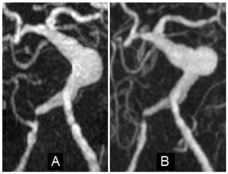
Maximum Intensity Projection (MIP) images from MRA studies of a patient with a giant basilar aneurysm: (A) Image of aneurysm at maximum size; (B) Image acquired nine months after A.
Patient 2
This patient had an aneurysm representing a moderate dilation of the mid-basilar artery (6.6 mm maximum diameter). Using MRA, an initial increase in lumenal volume was observed, followed by a substantial reduction of the volume of the aneurysmal segment (Figure 2). The FFE images confirmed that part of the aneurysm volume was occupied by thrombus.
Figure 2.
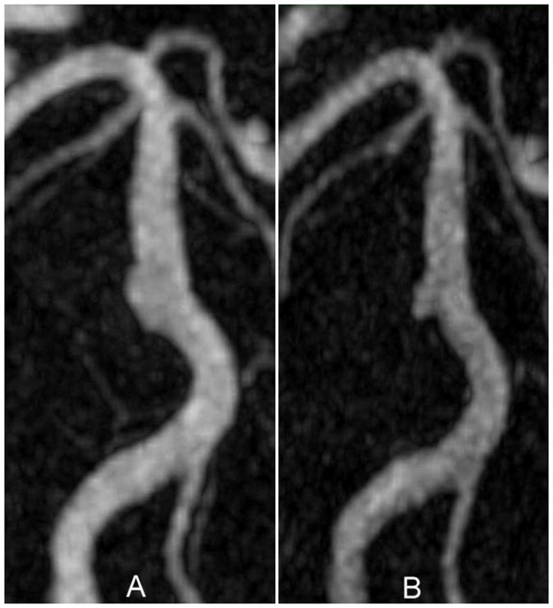
MIP images from an MRA study on a patient with a basilar aneurysm: (A) Image of aneurysm at maximum size; (B) Image acquired seven months after A.
Patient 3
In the third case, the intra-aneurysmal thrombus formed following surgical occlusion of one vertebral artery. This case was extensively analyzed in our previous work using an assumption of Newtonian viscosity.21 The patient presented with a rapidly growing giant basilar aneurysm and symptoms of brain stem compression (Fig. 3a). Because of the aneurysm size (18 mm in diameter) and the rapid rate of growth, a clinical decision was made to take down both vertebral arteries and to provide retrograde revascularization of the basilar artery via a bypass from one vertebral artery, immediately proximal to the site of occlusion, to the superior cerebellar artery. The complete procedure was planned as a two-stage process. In the first stage, the bypass was completed and the right vertebral artery was clip-occluded distal to the anastomosis (at the location shown by arrow 1 in Figure 3b). Both MR imaging and catheter angiography performed within 24 hrs following this procedure demonstrated a dramatic reduction in caliber of the lumen of the aneurysmal vessel (Figure 3b). A decision was therefore made not to proceed with the second stage but to leave the left vertebral artery unclipped.
Figure 3.

MIP of CE-MRA studies: a) giant basilar aneurysm presenting with rapid growth before surgery; b) after clipping of the right vertebral artery. Arrow 1 shows the clip location on the right vertebral artery; arrow 2 points at the bypass connecting the clipped vertebral to the superior cerebellar artery (Note that the remainder of the bypass lies outside the imaging volume and is not visualized).
MR Imaging
The base-line and follow-up (following thrombus deposition) geometry of the lumenal boundaries were obtained from high resolution, contrast-enhanced MRA (CE-MRA) images of the cerebral blood vessels using an intravenous injection of 20cc GdDTPA injected at 2cc/s. The spatial resolution of the CE-MRA study was 0.6 × 0.63 × 1.2 mm. Flow inlet conditions required for the CFD modeling were measured in the proximal feeding arteries using in vivo MR velocimetry. MR imaging of soft tissue was performed using a 3D steady-state method (balanced fast-field echo) acquired with 1mm thick partitions and 0.8 × 0.8 mm in-plane resolution.
Model construction
Patient-specific lumenal geometries of the basilar aneurysms were generated from CE-MRA images of the cerebral blood vessels. In-house software was used to form a three-dimensional iso-surface from a set of MRA slices. In order to obtain this iso-surface, a threshold intensity value was selected that defined the intra-lumenal volume of the vessels. The three-dimensional surface was co-registered with the two-dimensional MR slices and the threshold level was then adjusted to ensure that the segmented surface coincided with the lumenal boundaries of the MR gray-scale data. The surface was then transferred into 3D modeling software, Rapidform (INUS Technology, Seoul, South Korea), where the volume of interest, which included the aneurysm with the proximal and distal vessels, was selected while the other vessels, as well as the smaller perforators branching of the aneurysm, and background noise were removed. Remaining singularities and spikes were then manually eliminated and holes in the surface were filled. Laplacian smoothing was then applied to make the surface continuous and regular; care was taken to conserve the global volume of the model by iterating between the contraction and expansion passes of the smoothing filter. The lumenal surfaces thus obtained from the base-line and follow-up MRA studies were co-registered to visualize and quantify the geometric changes that resulted from thrombus formation. In order to ensure that differences were due to actual physiological changes rather than to differences in image processing, cerebral vessels unaffected by aneurysmal disease were used as a reference. The threshold settings were chosen so that the volume of the non-aneurysmal vessel segments in the follow-up model was the same as that in the base-line model. This threshold was then used for the entire follow-up geometry and the aneurysm surface was co-registered with the surface obtained at base-line. Regions determined to correspond to thrombus on the soft tissue MRI were correlated with locations of pronounced reduction in lumen size on the CE-MRA studies to confirm that those were indeed regions of thrombus formation.
CFD models were constructed using the geometries and inlet flow conditions measured with MRA at baseline. The surfaces obtained with Rapidform were divided into a number of rectangular patches for import into the CFD preprocessor Gambit (Fluent Inc., Lebanon, NH), to be used as the boundaries for the computational grid.
Boundary conditions
MR velocimetry data were used to determine patient-specific inlet flow conditions. Flow velocities in the vertebral arteries proximal to the aneurysm were measured with phase-contrast MRI (PC-MRI) scanning. Planes transverse to the vertebral and basilar arteries were determined from the three-dimensional CE-MRA data set. Acquisition parameters were: slice thickness, 5 mm; field of view, 150 mm. The in-plane pixel size was 1.1 × 1.1 mm. An electrocardiogram-triggered through-plane PC-MRI was acquired at 40-millisecond intervals through the cardiac cycle using a velocity-encoding level of 50 cm/s, providing approximately fifteen time points through the cardiac cycle. These measurements were used to prescribe time-dependent inlet boundary conditions. Since geometry of the proximal vessels profoundly affects the intra-aneurysmal flow 2, all the models contained a relatively extended length of vertebral arteries proximal to the basilar artery. The length of these proximal vessels reduced the importance of the flow profiles prescribed at the inlet to the model and, for simplicity, uniform velocities (calculated from the known inlet cross-sectional area of the model) were therefore assumed. It was further assumed that the flow exiting from the aneurysm divides equally between the distal cerebral arteries since it is reasonable to assume that the two hemispheres in the posterior circulation receive comparable total volume flow.
Numerical methods
The governing incompressible Navier-Stokes equations were solved numerically with a finite-volume package, Fluent (Fluent Inc., Lebanon, NH). This solver has been successfully used in various biological fluid dynamics applications and has been extensively validated with experimental data. The arterial walls were assumed rigid. This is a reasonable assumption, since aneurysmal blood vessels lack elastin and therefore have little compliance7. Second-order schemes were used for numerical discretization in space and time. A segregated, implicit solver was used to solve the continuity and momentum equations. A pressure-velocity coupling algorithm PISO (Pressure-Implicit with Splitting of Operators) was employed to compute pressure using the continuity equation. For each patient, pulsatile flow simulations were conducted in the base-line geometry using the measured, time-dependent flowrates, and three cardiac cycles were modeled to reduce the effect of the initial transients. The iteration steps were repeated until convergence was reached, as indicated by a four-order magnitude reduction of the residuals. A steady-state solution was used as initial condition for the pulsatile simulation.
For each patient both Newtonian and non-Newtonian flow simulations were carried out. The Newtonian flow assumption, commonly used to model the flow in large arteries, may not be adequate for the flow in aneurysmal vessels where low shear rates observed in regions filled with slow, recirculating flows can cause blood to exhibit non-Newtonian behavior.5, 13, 26, 30 The Non-Newtonian viscosity was modeled with the Herschel-Bulkley formula. The Herschel-Bulkley model extends a simple power law formula to include yield stress τ0:
where γ̇ is the strain rate. The experimental values provided by Kim12 were used for coefficients k and n. This model, which captures shear thinning and provides a good fit over a range of shear rates, has been particularly popular in recent studies.4, 9, 26, 30, 31
Computational grids with different densities were constructed for each of the patients and steady flow solutions from different grid densities were compared against each other to ensure mesh independence is achieved. The density of the grid was controlled by specifying the size of the grid elements, and each refinement resulted in reducing the minimum element size by a factor of two. For Patient 1, for example, 4 grids with the nominal element size from 0.125 mm3 to 0.0156 mm3 were compared, with roughly 180, 370, 600, and 1,300 thousand computational cells. For each grid, the average wall shear stress (WSS) was computed for the total surface of the model and for the region in the aneurysm bulge. The grid was incrementally refined, and with consecutive refinements the differences in calculated WSS values between one grid resolution and the next grid resolution was reduced from 7% to 2.3% averaged over the total area, and from 27% to 2.2% averaged over the area of the aneurysm bulge alone. This was used to confirm mesh-independence of the solution.
Numerical and in vivo data comparison
The lumenal surfaces obtained with MRA prior to and after thrombus deposition were co-registered with velocity iso-surfaces computed with CFD using ParaView software (Kitware Inc., Clifton Park, NY). For each patient, velocity iso-surfaces obtained at peak systole and end diastole for different threshold values were compared with the lumenal surface constructed from the follow-up MRA study and the threshold corresponding to the best visual agreement was determined. This was a fairly rough process as we attempted to see if there is a certain velocity threshold related to thrombus deposition rather than accurately determine its value in each case. Threshold values between 1 and 3 m/s were considered adjusting the threshold in steps of 0.25 m/s. The threshold value providing the best visual similarity for most of the cardiac phases was selected. The same co-registration procedure was carried out for the co-registration of iso-surfaces obtained from both Newtonian and non-Newtonian simulations.
In order to obtain a quantitative comparison between the CFD and MRA data, a space-averaged velocity value was obtained for the regions that were observed to clot and for the regions that remained patent at the follow-up study. The proximal and distal vessels were excluded from this comparison so that the average velocities were calculated only in the diseased part of the vessels. For each patient, the changes of these space-averaged velocities during the cardiac cycle were plotted for Newtonian and non-Newtonian results.
The distribution of maximum shear stress, τMAX, was also calculated for each patient. The value of τMAX indicates the maximum possible shear stress level for a given shear stress tensor and is readily calculated as one half of the difference between the maximum and minimum eigenvalues of the shear stress tensor. Averaged maximum shear values were then calculated and plotted for the thrombosed and patent regions of the lumenal geometries, in a manner similar to that used in the velocity averaging described above. In addition, cross-sectional planes were used to visualize the maximum shear distribution in each patient at peak systole.
Results
Co-registration of base-line and follow-up lumenal geometries
Images of the lumenal geometries constructed from MR data taken at base-line and co-registered with the geometries obtained from MR data taken after thrombus deposition are presented in Figure 4. The base-line lumenal geometry is shown in gray and the lumen following the thrombus deposition is shown in black. The resulting percentage change of the lumenal volumes for Patient 1, Patient 2, and Patient 3 were equal to 51%, 22%, and 59% respectively.
Figure 4.

Co-registration of the base-line (gray) and follow-up (black) lumenal geometries showing the regions occupied by thrombus.
Flow patterns
The flow fields obtained in computational models constructed from base-line geometries are presented in Figure 5, showing the instantaneous flow streamlines at peak systole when the recirculation is minimal and at the end of diastole, when the recirculation regions are particularly evident. While the flow recirculating regions predicted with non-Newtonian models were larger than those obtained in the Newtonian case, these differences were difficult to perceive from the streamline plots, and therefore only Newtonian flow streamlines are presented.
Figure 5.

Flow streamlines showing regions of slow, recirculating flow in 3 basilar aneurysms. Top row: streamlines at peak systole; bottom row: streamlines at the end of diastole.
Patient 1 (left panel of Fig. 5)
The patient had a severe stenosis of the right vertebral artery, so roughly 90% of the flow entered through the left vertebral. The entering jet crosses the aneurysm and impinges on the opposite wall at the distal part of the aneurysm bulge. The majority of the flow then exits in a swirling motion through the distal vessels, while the remainder flows in a retrograde manner towards the back of the aneurysm, forming a large recirculating, slow flow region. This recirculation flow is particularly strong at the end of systole and, towards the end of diastole the flow in the bulge is close to stagnant.
Patient 2 (center panel of Fig. 5)
In this case one of the vertebral arteries is noticeably larger than the other so most of the flow is again provided by a single inlet vessel. The aneurysm size in this case is smaller and the inlet velocities are lower as well, which leads to weaker secondary flows and hence less complicated flow patterns. The main stream enters the basilar artery and proceeds toward the distal end of the vessel with almost no disturbances. A fraction of the flow, however, is trapped in the fusiform bulge and forms a tight vortex.
Patient 3 (right panel of Fig. 5)
In this simulation we were interested in the alteration of flow dynamics throughout the basilar territory immediately following surgery and therefore assumed that the lumenal geometry remained unchanged immediately following surgery but that the inlet flow changed. Therefore, while the geometries used for simulations were obtained from CE-MRA images acquired prior to the surgery, the prescribed inlet conditions correspond to post-surgical flow when the right vertebral is clipped. The simulations results show a high velocity jet entering through the remaining vertebral and quickly decelerating in the aneurysmal basilar artery. A large, slowly rotating vortex is formed in the aneurysm bulge resulting in almost stagnant local flow at all phases of the cardiac cycle.
Comparison of the CFD results with in vivo observations
A co-registration of the lumenal surfaces obtained with MRA prior to and after thrombus deposition, is in turn co-registered with CFD results obtained for these 3 patients. Velocity iso-surfaces were used to determine the flow regions with velocities below a certain threshold. The co-registration of the in vivo MRA data with the velocity iso-surfaces obtained from Newtonian and non-Newtonian flow simulations are shown in Figure 6 and Figure 7 respectively. In all figures, the difference between the baseline, thrombus-free geometry (shown in gray), and the follow-up geometry after thrombus formation (shown in blue) corresponds to the region occupied by the thrombus. Regions of the aneurysm lumen that remained free of thrombus at follow-up are referred to below, and particularly in Figures 8 and 10, as patent regions. The slow flow zone predicted by CFD is visualized by plotting a constant velocity surface. A velocity threshold was specified, and the corresponding iso-surface was plotted on top of the vessel outline surfaces, showing all the regions with velocities equal to or above the threshold value in red and leaving the regions with slower velocities blank. Since a clinically relevant threshold value has not previously been described, a value that was roughly 10% of the normal velocities observed in the proximal and distal vessels was selected. The velocity threshold value for Patients 1 and 3, shown in the left and right panel of the figures was set to 2.5 cm/s, while the threshold value for Patient 2, shown in the middle, was 1.5 cm/s, as the inlet velocities in this case were smaller. The same threshold value was used for Newtonian and non-Newtonian results. For each patient, the velocity iso-surfaces were obtained for all phases of the cardiac cycle. The co-registration results obtained for the iso-surfaces corresponding to peak systole and end diastole are shown in Figures 6 and 7. For all patients, the regions with the velocities below the threshold are located in the area where slow, recirculating flows were predicted.
Figure 6.

Co-registration of lumenal surfaces obtained from MRA prior to thrombus formation (gray) and after thrombus formation (blue) with velocity iso-surfaces predicted by Newtonian flow simulations (red). Top row: peak systole; bottom row: end diastole.
Figure 7.

Co-registration of lumenal surfaces obtained from MRA prior to thrombus formation (gray) and after thrombus formation (blue) with velocity iso-surface predicted by non-Newtonian flow simulations (red). Top row: peak systole; bottom row: end diastole.
Figure 8.

Space-averaged velocity changes through the cardiac cycle calculated using the base-line geometry for regions that remained patent and those that were occupied by thrombus in the follow up geometry. Solid and dashed lines correspond to Newtonian and non-Newtonian results respectively.
Figure 10.

Space-averaged “maximum shear” changes during the cardiac cycle calculated in the base-line geometry for regions remained patent and occupied by thrombus in the follow up geometry. Solid and dashed lines correspond to Newtonian and non-Newtonian results respectively.
Plots of the averaged velocities, calculated in the patent and clotted off regions for each phase of the cardiac cycle, are shown in Figure 8 for all patients. The average velocities were calculated in the aneurysmal vessels only; the proximal and distal arteries were not considered in this analysis. In all cases, the curves corresponding to the changes in averaged velocity in the regions that remained patent show marked pulsatile behavior, while those obtained from regions observed to clot the pulsatility is less evident; for Patients 1 and 3 the curves remain almost constant over the cardiac cycle. At any phase, the velocity values in the thrombosed regions are substantially smaller than those in the patent regions of the lesions. The non-Newtonian flow effects predicted smaller velocity values in both patent and clotted-off regions. The average percentage difference between the Newtonian and non-Newtonian velocities predicted in the regions of thrombus deposition was 31%, 29%, and 21% for Patient 1, Patient 2, and Patient 3 respectively. The differences in the regions that remained patent were smaller: 1%, 11%, and 4% respectively.
The maximum shear distribution calculated from the Newtonian results at peak systole is visualized using cross-sectional planes (Figure 9). The section planes are oriented to cut through the inlet jet as well as through the aneurysmal bulge. In a healthy vessel, the maximum shear is higher near the wall and lower towards the center, as can be observed where the cut-planes cross the arteries both proximal and distal to the aneurysms. In the aneurysmal vessels considered in this study, in contrast to this healthy shear patterns, there are regions where the maximum shear at the wall is abnormally low. There is an obvious similarity between the location of these areas of low maximum shear at the aneurysmal walls and the regions of thrombus deposition. The maximum shear values calculated from the non-Newtonian simulations are found to be higher than the values obtained from the Newtonian flow results; however the general patterns of the distribution remain essentially the same. This is demonstrated in Figure 10, showing the space-averaged maximum shear time-dependent behavior over the cardiac cycle. The maximum shear values calculated for the base-line geometry in the regions that were later observed to clot are substantially smaller than in the patent regions, and remain almost unchanged over the cardiac cycle. Again, the proximal and distal vessels were excluded from these calculations. The difference between the shear values in the patent and thrombosed regions in the non-Newtonian flow is more pronounced. The average difference between the Newtonian and non-Newtonian maximum shear values in the regions that remained patent is 21%, 23%, and 19% for Patient 1, Patient 2, and Patient 3 respectively. The average difference of the maximum shear predictions in the regions that were observed to clot is even higher: 29%, 26%, and 22% respectively.
Figure 9.

Distribution of maximum shear calculated from Newtonian flow simulations. Cross-sectional planes show low maximum shear in the regions that were occupied by thrombus in the follow-up geometry.
Discussion
These results demonstrate very good agreement between the location of regions predicted by CFD to have slow and recirculating flow with that of regions that were demonstrated in follow-up studies to have thrombosed. Slow recirculating flows reported in intracranial aneurysms1, 22, 23, 25 may cause extended residence time and lead to compromised mass transfer, potentially causing blood coagulation. Pulsatility has a profound effect on the flow patterns, resulting in changes of the recirculating flow regions over the cardiac cycle. The velocity iso-surfaces, therefore, were substantially different at different phases of the cycle, which makes their comparison with the MRA data quite challenging. It is possible that only a minimal recirculation zone, as represented by velocity iso-surfaces at peak systole, should be considered, since the clotting is less likely to occur in regions experiencing higher flow for at least some part of the cardiac cycle. The formation of thrombus may occur over a short time interval rather than as a slow layering process. In two of the patients considered in the study, the evolution of thrombus is unknown and it could have formed at any time during the several months period between the base-line and follow-up studies. In the third case, however, it is known that the thrombus formed within 24 hours following the surgery.
The effects of non-Newtonian blood behavior in slow, recirculating flows are likely to change flow patterns and velocities in these regions.5, 13, 26, 30 There are several studies that incorporate non-Newtonian flow in aneurysmal vessels.8, 11, 17, 19, 31, 32 Different constitutive models were employed to calculate non-Newtonian blood viscosity, the most widely used being the Casson and Herschel-Bulkley models which take into account shear thinning as well as yield stress. In two recent works Valencia et al used a Herschel-Bulkley constitutive model in numerical simulations of pulsatile flow in saccular aneurysms.31, 32 Similar velocity fields were observed in both Newtonian and non-Newtonian models, however for the latter case, lower wall shear stresses were reported in the regions with high velocity gradients. For two of the patients considered in the current study, the agreement between CFD velocity iso-surfaces and follow-up lumenal geometries improved when non-Newtonian effects were included. For Patient 1 and Patient 3, the region with velocities smaller than 2.5 cm/s was considerably larger in the non-Newtonian case (Figure 7). Comparison of the lumenal changes obtained from MRA data with velocity iso-surfaces calculated from CFD reveals a strong similarity between the slow flow regions predicted in non-Newtonian flow simulations and the regions that were observed to fill with clot in vivo. For Patient 2, however, the non-Newtonian effects do not improve the agreement with in vivo observations. The difference between the Newtonian and non-Newtonian maximum shear values calculated in Patient 2 model were also smaller. This may be explained by the fact that the aneurysms of Patients 1 and 3 were very large (15.7 and 18 mm in diameter), with large regions of slow recirculating flows where low strain rates could cause non-Newtonian blood behavior. The values of the space-averaged velocities predicted in the non-Newtonian simulations were lower than those obtained for Newtonian flow, which may further facilitate thrombus deposition. The maximum shear values predicted by the non-Newtonian model were higher than those in the Newtonian case (Figure 10). Comparison of the velocity gradients (strain rates) computed in the Newtonian and non-Newtonian simulations showed that non-Newtonian velocity gradients were smaller. The opposite results for the maximum shear were, therefore, caused by the higher values of molecular viscosity, calculated using the Herschel-Bulkley formula. The non-Newtonian viscosity values were apparently overestimated in the low shear regions, including the regions that remained patent; we will address this issue in our future studies by adjusting the constants used in the non-Newtonian viscosity formula. The difference between the Newtonian and non-Newtonian results observed in two aneurysm models suggest that non-Newtonian blood properties should be taken into account for numerical analysis of the flows in giant aneurysms.
Hemodynamic parameters such as shear rate and vorticity are likely to play an important role in thrombus formation, since blood viscosity and therefore coagulation depend on velocity gradients. Numerical simulations are particularly important for the evaluation of these parameters, as resolution of the in vivo and even in vitro methods may be inadequate for the purpose. It is convenient to define a scalar variable representing the stress in the fluid, rather than work with the six independent components of the viscous stress tensor. In this study we calculated the maximum shear variable, similar to the maximum shear used in solid mechanics and strength of materials analysis. The maximum shear field calculated in the aneurysms demonstrated a good match between the areas of low maximum shear at the aneurysmal walls and the regions of thrombus deposition. It is possible that in such regions the clot can attach to the wall, while it is washed off in the regions with higher shear stresses. Thus, the maximum shear may be an important hemodynamic parameter for the determination of the intra-lumenal thrombus location.
While the CFD velocity iso-surfaces do not exactly match the observed post-surgical lumen, there is a strong similarity between the slow flow zones predicted by CFD and the regions of thrombus deposition observed in vivo. We do not claim, however, that flow stagnation is the primary cause of thrombus formation. Indeed, if slow velocity were a sufficient condition for clotting, thrombus would immediately form in the smaller arterioles, capillaries and, particularly, in veins, where the velocities are smaller than the threshold value considered in our study.
The mechanism for thrombus formation is still poorly understood. The few mathematical models of the process are difficult to implement, as it requires multi-scale modeling in both space and time.
Despite the limitations of the study, our initial results suggest that regions in intracranial aneurysm with low velocities (smaller than 2.5cm/s in giant aneurysms) and low shear stress at the walls are particularly prone to thrombus formation. The good agreement between regions above that velocity threshold and regions that remained patent at the follow-up time point indicate that this value could have clinical relevance. The study demonstrates that numerical modeling of the intra-aneurysmal flow can provide valuable information for the evaluation of aneurysm treatment options on a patient-specific basis. Recent studies have shown that CFD can be a useful tool for the assessment of aneurysmal wall growth.10 This report indicates that, in addition, numerical analysis may be able to predict regions at higher risk of thrombus deposition, thus providing guidance for clinicians.
Conclusions
Numerical simulations of the flow in three patient-specific intracranial aneurysm models indicate that regions of thrombus formation correspond to slow flow and low shear regions. Predictions of numerical simulation methods are consistent with changes observed in longitudinal MRI studies of aneurysm geometry. Accounting for non-Newtonian blood behavior improved the agreement between the low velocity and thrombus deposition regions in giant aneurysms. MR imaging was demonstrated to provide the boundary conditions needed for determination of important hemodynamic descriptors. This study indicates that computational models may provide hypotheses to test in future studies, and might offer guidance for the interventional treatment of cerebral aneurysms.
References
- 1.Burleson A, Strother C, Turitto V. Computer Modeling of Intracranial Saccular and Lateral Aneurysms for the Study of Their Hemodynamics. Neurosurgery. 1995;37(4):774–84. doi: 10.1227/00006123-199510000-00023. [DOI] [PubMed] [Google Scholar]
- 2.Castro MA, Putman CM, Cebral JR. Computational Fluid Dynamics Modeling of Intracranial Aneurysms: Effects of Parent Artery Segmentation on Intra-Aneurysmal Hemodynamics. American Journal of Neuroradiology. 2006;27:1703–1709. [PMC free article] [PubMed] [Google Scholar]
- 3.Cebral JR, Castro MA, Appanaboyina S, et al. Efficient Pipeline for Image-based Patient-specific Analysis of Cerebral Aneurysm Hemodynamics: Technique and Sensitivity. IEEE Transaction on Medical Imaging. 2005;24(4):457–467. doi: 10.1109/tmi.2005.844159. [DOI] [PubMed] [Google Scholar]
- 4.Chaturani P, Samy RP. A study of non-Newtonian aspects of blood flow through stenosed arteries and its applications in arterial diseases. Biorheology. 1985;22:521–531. doi: 10.3233/bir-1985-22606. [DOI] [PubMed] [Google Scholar]
- 5.Choi HW, Barakat AI. Numerical study of the impact of non-Newtonian blood behavior on flow over a two-dimensional backward facing step. Biorheology. 2005;42:493– 509. [PubMed] [Google Scholar]
- 6.Hassan T, Ezura M, Timofeev EV, et al. Computational simulation of therapeutic parent artery occlusion to treat giant vertebrobasilar aneurysm. Am J Neuroradiol. 2004;25:63–68. [PMC free article] [PubMed] [Google Scholar]
- 7.Humphrey JD, Na S. Elastodynamics and Arterial Wall Stress. Ann Biomed Eng. 2002;30:509–523. doi: 10.1114/1.1467676. [DOI] [PubMed] [Google Scholar]
- 8.Imbesi SG, Kerber CW. Analysis of slipstream flow in a wide-necked basilar artery aneurysm: evaluation of potential treatment regimes. Am J Neuroadiol. 2001;22:721–724. [PMC free article] [PubMed] [Google Scholar]
- 9.Johnston BM, Johnston PR, Corney S, Kilpatrick D. Non-Newtonian blood flow in human right coronary arteries: transient simulations. J Biomech. 2006;39:1116–1128. doi: 10.1016/j.jbiomech.2005.01.034. [DOI] [PubMed] [Google Scholar]
- 10.Jou LD, Wong G, Disensa B, et al. Correlation between lumenal geometry changes and hemodynamics in fusiform intracranial aneurysms. Am J Neuroradiol. 2005;26:2357–2363. [PMC free article] [PubMed] [Google Scholar]
- 11.Kerber CW, Hecht ST, Knox K, et al. Flow dynamics in a fatal aneurysm of the basilar artery. AJNR Am J Neuroradiol. 1996;17:1417–1421. [PMC free article] [PubMed] [Google Scholar]
- 12.Kim S. A study of non-Newtonian viscosity and yield stress of blood in a scanning capillary-tube rheometer. Drexel University; 2002. [Google Scholar]
- 13.Liepsch DW. Effect of flood flow parameters on flow patterns at arterial bifurcations studies in models. In: Liepsch DW, editor. Blood Flow in Large Arteries: Applications to Atherogenesis and Clinical Medicine, Monographs on Atherosclerosis. Vol. 15. Basel: Karger; 1990. pp. 63–76. [PubMed] [Google Scholar]
- 14.Long Q, Xu XY, Ariff B, et al. Reconstruction of blood flow patterns in a human carotid bifurcation: a combined CFD and MRI study. J Magn Reson Imaging. 2000;11:299–311. doi: 10.1002/(sici)1522-2586(200003)11:3<299::aid-jmri9>3.0.co;2-m. [DOI] [PubMed] [Google Scholar]
- 15.Long Q, Xu XY, Bourne M, Griffith TM. Numerical study of blood flow in an anatomically realistic aorto-iliac bifurcation generated from MRI data. Magn Reson Med. 2000;43:565–576. doi: 10.1002/(sici)1522-2594(200004)43:4<565::aid-mrm11>3.0.co;2-l. [DOI] [PubMed] [Google Scholar]
- 16.Long Q, Xu XY, Collins MW, et al. The combination of magnetic resonance angiography and computational fluid dynamics: a critical review. Crit Rev Biomed Eng. 1998;26:227–274. doi: 10.1615/critrevbiomedeng.v26.i4.10. [DOI] [PubMed] [Google Scholar]
- 17.Low M, Perktold K, Raunig R. Hemodynamics in rigid and distensible saccular aneurysms: a numerical study of pulsatile flow characteristics. Biorheology. 1993;30:287–298. doi: 10.3233/bir-1993-303-413. [DOI] [PubMed] [Google Scholar]
- 18.Mantha A, Karmonik C, Benndorf G, et al. Hemodynamics in a cerebral artery before and after the formation of an aneurysm. Am J Neuroradiol. 2006;27:1113–1118. [PMC free article] [PubMed] [Google Scholar]
- 19.Perktold K, Peter R, Resch M. Pulsatile non-Newtonian blood flow simulation through a bifurcation with an aneurysm. Biorheology. 1989;26:1011–1030. doi: 10.3233/bir-1989-26605. [DOI] [PubMed] [Google Scholar]
- 20.Rayz VL, Boussel L, Acevedo-Bolton G, et al. Numerical simulations of flow in cerebral aneurysms: comparison of CFD results and in vivo MRI measurements. J Biomech Eng. doi: 10.1115/1.2970056. In press. [DOI] [PubMed] [Google Scholar]
- 21.Rayz VL, Lawton MT, Martin AJ, et al. Numerical simulation of pre-and post-surgical flow in a giant basilar aneurysm. J Biomech Eng. 2008;130:021004. doi: 10.1115/1.2898833. [DOI] [PubMed] [Google Scholar]
- 22.Steiger H, Poll A, Liepsch D, Reulen H. Basic Flow Structure in Saccular Aneurysms: A Flow Visualization Study. Heart & Vessels. 1987;3:55– 65. doi: 10.1007/BF02058520. [DOI] [PubMed] [Google Scholar]
- 23.Steiger HJ, Poll A, Liepsch D, Reulen HJ. Hemodynamic Stress in Lateral Saccular Aneurysms. Acta Neurochir. 1987;86:98–105. doi: 10.1007/BF01402292. [DOI] [PubMed] [Google Scholar]
- 24.Steinman DA. Image-Based Computational Fluid Dynamics Modeling in Realistic Arterial Geometries. Annals of Biomedical Engineering. 2002;30:483–497. doi: 10.1114/1.1467679. [DOI] [PubMed] [Google Scholar]
- 25.Steinman DA, Milner JS, Norley CJ, et al. Image-based computational simulation of flow dynamics in a giant intracranial aneurysm. Am J Neuroadiol. 2003;24:559–566. [PMC free article] [PubMed] [Google Scholar]
- 26.Stroud JS, Berger SA, Saloner D. Numerical analysis of flow through a severely stenotic carotid artery bifurcation. J Biomech Eng. 2002;124:9–20. doi: 10.1115/1.1427042. [DOI] [PubMed] [Google Scholar]
- 27.Tateshima S, Murayama Y, Villablanca JP, et al. Intraaneurysmal flow dynamics study featuring an acrylic aneurysm model manufactured using a computerized tomography angiogram as a mold. J Neurosurg. 2001;95:1020–1027. doi: 10.3171/jns.2001.95.6.1020. [DOI] [PubMed] [Google Scholar]
- 28.Tateshima S, Tanishita K, Omura H, et al. Intra-aneurysmal hemodynamics during the growth of an unruptured aneurysm: in vitro study using longitudinal CT angiogram database. AJNR. 2007;28(4):622–7. [PMC free article] [PubMed] [Google Scholar]
- 29.Taylor CA, Draney MT, Ku JP, et al. Predictive medicine: computational techniques in therapeutic decision-making. Computer Aided Surgery. 1999;4:231–247. doi: 10.1002/(SICI)1097-0150(1999)4:5<231::AID-IGS1>3.0.CO;2-Z. [DOI] [PubMed] [Google Scholar]
- 30.Tu C, Deville M. Pulsatile flow of non-Newtonian fluids through arterial stenosis. J biomech. 1996;29:899–908. doi: 10.1016/0021-9290(95)00151-4. [DOI] [PubMed] [Google Scholar]
- 31.Valencia A, Zarate A, Galvez M, Badilla L. Non-Newtonian blood flow dynamics in a right internal carotid artery with a saccular aneurysm. Int J Numer Meth Fluids. 2006;50:751–764. [Google Scholar]
- 32.Valencia AA, Guzma’n AM, Finol EA, Amon CH. Blood Flow Dynamics in Saccular Aneurysm Models of the Basilar Artery. J Biomech Eng. 2006;128:516–526. doi: 10.1115/1.2205377. [DOI] [PubMed] [Google Scholar]
- 33.Wang KC, Dutton RW, Taylor CA. Improving geometric model construction for blood flow modeling. IEEE Eng Med Biol Mag. 1999;18:33–39. doi: 10.1109/51.805142. [DOI] [PubMed] [Google Scholar]
- 34.Zhao SZ, Xu XY, Hughes AD, et al. Blood flow and vessel mechanics in a physiologically realistic model of a human carotid arterial bifurcation. J Biomech. 2000;33:975–984. doi: 10.1016/s0021-9290(00)00043-9. [DOI] [PubMed] [Google Scholar]