

Abstract
Object
The PASADENA method has achieved hyperpolarization of 16–20% (exceeding 40,000-fold signal enhancement at 4.7 T), in liquid samples of biological molecules relevant to in vivo MRI and MRS. However, there exists no commercial apparatus to perform this experiment conveniently and reproducibly on the routine basis necessary for translation of PASADENA to questions of biomedical importance. The present paper describes equipment designed for rapid production of six to eight liquid samples per hour with high reproducibility of hyperpolarization.
Materials and methods
Drawing on an earlier, but unpublished, prototype, we provide diagrams of a delivery circuit, a laminar-flow reaction chamber within a low field NMR contained in a compact, movable housing. Assembly instructions are provided from which a computer driven, semiautomated PASADENA polarizer can be constructed.
Results
Together with an available parahydrogen generator, the polarizer, which can be operated by a single investigator, completes one cycle of hyperpolarization each 52 s. Evidence of efficacy is presented. In contrast to competing, commercially available devices for dynamic nuclear polarization which characteristically require 90 min per cycle, PASADENA provides a low-cost alternative for high throughput.
Conclusions
This equipment is suited to investigators who have an established small animal NMR and wish to explore the potential of heteronuclear (13C and 15N) MRI, MRS, which harnesses the enormous sensitivity gain offered by hyperpolarization.
Keywords: Hyperpolarization, PASADENA polarizer, 13Carbon, Parahydrogen, Hydroxyethylacrylate, PHIP
Introduction
Several promising methods of improving NMR signal, including high field, rapid gradients, parallel r.f. excitation and acquisition, super-cooled r.f.-coils, rapid imaging and magnetization transfer sequences, as well as paramagnetic contrast agents, all operate within the constraints of thermal nuclear spin polarization (P ~ 10−6 at ambient temperatures), described by the Boltzmann distribution, and therefore provide only incremental improvements in signal to noise ratio (SNR), varying from 2–10-fold [1]. A family of hyperpolarization techniques on the other hand, addresses the issue of low SNR by developing polarization several orders of magnitude greater than the polarization at thermal equilibrium, and use a variety of physical and chemical methods to approach polarization of unity (P = 100%). Hyperpolarized noble gas imaging of the lungs is the most familiar to in vivo MR scientists and clinicians since human studies have been in progress with helium for more than 10 years, and with xenon for two or more years [2]. Hyperpolarized heteronuclear NMR with 13C and 15N became available for in vivo applications through the systematic improvement and exploitation of dynamic nuclear polarization (DNP) [3] and parahydrogen induced polarization (PHIP), a.k.a. PASADENA (parahydrogen and synthesis allow dramatically enhanced nuclear alignment) after its original inventors [4]. DNP, although restricted to license-holders, is nevertheless more available to investigators as a result of two commercial developments (Oxford Biotools—HyperSense; GE Healthcare). PASADENA, on the other hand, is available to only very few laboratories, each of which has constructed unique equipment and for which no designs are published. This has the disadvantage of limiting studies to improve on and examine the merits of these methodologies and limits another future objective, multi-site comparison which will suffer the handicap of comparing different equipments.
The present paper is written to overcome this barrier. We describe construction of a simple polarizer which will provide low-cost access to PASADENA hyperpolarization, allow a systematic comparison between DNP and PASADENA and encourage avenues which appear to offer great promise for in vivo hyperpolarized MR studies not readily amenable to DNP or hyperpolarized noble gases. While the ground breaking early discoveries, and some of the subsequent evolution of the PASADENA method [5] required only an NMR spectrometer, an unsaturated molecule and a supply of parahydrogen gas, levels of hyperpolarization reported were generally around 1%, insufficient for biological, pre-clinical or clinical studies. A polarizer interface is needed to allow for rapid mixing and chemical reaction of parahydrogen, 13C (or 15N) enriched precursor in a catalyst solution under the correct conditions, within a low field NMR unit. The high spin order inherent in parahydrogen is quantitatively transferred to the precursor, with subsequent generation of the hyperpolarized 13C imaging reagent for injection into an animal or biological test system held within a conventional NMR spectrometer. With this device, high levels of hyperpolarization permitted early in vivo studies, which proved the potential of hyperpolarized 13C MRI in biology [6]. Ideally, and within a few minutes, the process is repeated, with the same or very comparable volume and hyperpolarization of the product. The PASADENA polarizer to be described advances upon the prototype described briefly by Axelsson et al. [6] (GE/Amersham, Malmö, Sweden). It is re-designed to be reliable, low cost and to produce hyperpolarized biomolecules in solution quickly and efficiently in amounts re-defined for small animal use. Unlike the previous design, which required the constant attention of 4–5 dedicated and highly trained individuals and was variable in its performance, a single person can operate this apparatus after a single demonstration. Quality Assurance (QA) procedures (described elsewhere) are developed which ensure reproducible hyperpolarization of biomolecules of P = [15.3 ± 1.9]% [7].
Materials and methods
The functional components of the polarizer presented are a hydrogenation compartment (laminar flow reaction chamber), a coil to transmit r.f. pulses (B1), and an electromagnet to generate the static field (B0) (Fig. 1a, b). A computer interface controls the experimental sequence of fluids and NMR. The entire apparatus is contained in a mobile housing located (7.6 ± 0.1) m distant from an unshielded 4.7 T magnet (stray field 0.1 mT). With appropriate r.f. and magnetic field shielding, this distance could be further reduced, with the aim of minimizing the delivery time from the polarizer outlet to the imaging target within the MR system.
Fig. 1.

PASADENA Laminar flow polarizer. a Photograph and b schematic view of the experimental setup. a Low-pass filter, r.f. amplifier, gauss meter, B0 power supply and reaction compartment, on top of the rack for the computer and synthesizer, parahydrogen (left) and nitrogen (right) gas tanks (top to bottom). b Functional elements in the reaction compartment: B0 coil, B1 coil, and reactor. The valves for fluid control are indicated with number {V1}–{V5}. During a PASADENA experiment, 1 the reactor is filled with parahydrogen to a pressure of 10 bar, 2 the precursor molecule is injected through the center of the injection cap, and 3 the r.f. spin order transfer sequence is applied after a reaction time of 3 s. Thereafter, the hyperpolarized agent is withdrawn through the end cap and delivered to the detecting MR unit
A second aspect of the instrumentation is the parahydrogen generator unit, necessary for the discontinuous production of parahydrogen of high purity (97–100%). This unit can be located off-site, with only sufficient gas held in a transport cylinder on site, for a full day of operation of the polarizer.
Components of PASADENA polarizer
The equipment to be described is illustrated and summarized under five headings: (1) fluid control unit, (2) low field NMR unit, (3) process control unit, (4) parahydrogen generator unit, (5) chemicals and ancillary equipment, to prepare the precursor and catalyst solution (Tables 1, 2, 3, 4, and 5).
Table 1.
Fluid control unit
| Function | Part | Description | Commercially available (Y = Yes)a |
|---|---|---|---|
| Transport and reaction | Tubing | PTFE tubing | Y1 |
| Valves | Electromagnetic solenoid and manual valves | Y2,3,4 | |
| Ante chamber | PTFE tubing | Y1 | |
| Reaction chamber | Injection cap, reactor body, end cap | – | |
| Auxiliary | T control | Heater, fan, controller, relay | Y5 |
| Injection timer | On-delay relay | Y6 | |
| Intake precursor | Rubber piston syringe | Y7 |
See Appendix for suppliers 1–39
Table 2.
Low field NMR unit
| Function | Part | Description | Commercially available |
|---|---|---|---|
| B1 field | B1 coil | Saddle-shaped coil | – |
| Synthesizer | DAC analog-out | Y8 | |
| Amplifier | Audio amplifier | Y9 | |
| Filter | 150kHz low-pass filter | Y10 | |
| Monitoring | Oscilloscope | Y11 | |
| Cables | Coaxial cable RG58 | Y12 | |
| B0 field | B0 coil | Solenoid coil | – |
| Power supply | DC power supply | Y13 | |
| Monitoring | Gauss meter | Y14 |
Table 3.
Process control unit
| Function | Part | Description | |
|---|---|---|---|
| Software | Platform | LabView | Y15 |
| Program | PASADENA control V1.1 | – | |
| Hardware | Synthesizer | DAC analog-out | Y8 |
| Valve, trigger control | DAC digital-out | Y16 | |
| Relays | Y17 |
Table 4.
Parahydrogen generator
| Function | Description | |
|---|---|---|
| Low T unit | Helium two-stage cold head | Y18 |
| Pressure gauge | Y19 | |
| Vacuum shroud | Y20 | |
| Helium compressor/cryodrive | Y21 | |
| Vacuum pump | Y22 | |
| Valve | Y23 | |
| Flow limiter | Y24 | |
| Relay | Y25 | |
| Pressure display | Y26 | |
| Water cooler | Y27 | |
| Tubing connectors | Y28 | |
| Regulator for H2 supply | Y29 | |
| Tubing at ambient T | Y30 | |
| Flow meter | Y31 | |
| Catalytic converter | Low T conversion container | Y32 |
| Catalyst | Y33 | |
| Storage | Cylinder | Y34 |
Table 5.
Chemicals and auxiliary
| Function | Part | Description | |
|---|---|---|---|
| Chemicals | Precursor | 1-13C FUM-d2, 1-13C HEA-d3 | Y35,36 |
| Catalyst | Rh-complex and ligand | Y37,38 | |
| Solvent | D2O, H2O, buffer | Y39 | |
| Aux. lab. equipment | Schlenk line with vacuum, N2, in fume hood | Y39 | |
| Glassware | Y39 | ||
| Precision scale | Y39 |
A diagram of the functional elements is shown in Fig 1b. In the following text, curved brackets refer to the valves in this figure. Suppliers of all components listed in Tables 1, 2, 3, 4, and 5 are identified in the Appendix. In brief, the 13C-enriched precursor-molecule together with the catalyst (in aqueous or deuterium oxide solution) is prepared, and brought to the injection port {V2} of the polarizer. A desired volume is then injected and resides briefly in a heating coil (ante chamber), before it is injected to the laminar flow reactor, which was filled previously with the second reactant, parahydrogen, via port{V1}. After a short reaction period, while substrate, parahydrogen, and catalyst are held in the reactor, a series of pulses played out in the B1 coil enacts a spin-order transfer sequence specific to the product of the hydrogenation reaction. The hyperpolarized product is ejected from the reaction vessel under the pressure of gas, filtered to remove catalyst and injected into an animal, organ or cell preparation previously mounted in the bore of a detecting high-field NMR spectrometer. A trigger encoded by the polarizer initiates in vitro or in vivo acquisition. Each cycle of generation, delivery and detection of hyperpolarization is completed in 55 s, which is less than 5 × T1(T1: longitudinal spin relaxation, lifetime of the hyperpolarization) of the injected hyperpolarized contrast reagent. The entire procedure including hyperpolarization, imaging, rinsing and reloading the polarizer with precursor, occupies 182 s (Table 6).
Table 6.
Workflow of the PASADENA experiment: manual preparation for cleaning, preheating and automated procedure for precise timing
| (a) Step | (b) Time point | (c) Description | (d) Duration |
|---|---|---|---|
|
1. Manual preparation | |||
| (1) | 0 s | clean polarizer: flush lines and reactor with 14 bar N2 gas, valve {V2}, {V3}, {V4}, {V5}. | 10 s |
| (2) | 10 s | preheat precursor solution: transfer 3.5 mL of precursor into the injection line {V2}. | 120s |
| total duration of manual preparations: 130 s | |||
|
| |||
|
2. Automated procedure | |||
| (3) | 0 s | hydrogenation reaction: fill reaction chamber with parahydrogen {V1}. inject the precursor into the reactor {V3, V4}. Ap | 10 s |
| (4) | 10 s | r.f. 1H decoupling sequence. | 3 s |
| (5) | 13 s | hyperpolarization: apply r.f. spin order transfer sequence. | >1 s |
| (6) | 14 s | delivery and detection: expel hyperpolarized agent {V5}. | 2 s |
| (7) | 19 s | delivery to the detection system | 28 s |
| (8) | 52 s | send trigger signal | 3 s |
| Total duration of hyperpolarization, delivery, and detection: 55s | |||
The numbers in curved brackets refer to valves in Fig. 1b
Fluid control unit
Valves and lines: fluid flow is controlled by electromagnetic solenoid valves, connected by chemical resistant polytetrafluoroethylene (PTFE, Teflon) tubing. A PTFE sleeve was added to the valves to prevent liquids from coming into contact with metal, allowing for a wide range of pH usage (Table 1).
Ante chamber: PTFE tubing with a inner volume of 5 mL is coiled within the heated compartment, leading from the injection port {V2} to the intake valve {V4} of the laminar flow reaction chamber.
The laminar flow reaction chamber is machined from PSU 1000 polysulfone (tensile strength: 11,600 psi, maximum service temperature: 150°C) to hold the pressure and temperature in excess of 15 bar and 70°C, respectively (Fig. 2). It consists of three sections: the injection cap, reactor body and extraction cap. The injection cap is disc-shaped with one inlet for each parahydrogen, and nitrogen/precursor solution. An outlet at the funnel-shaped floor of the reactor allows for the ejection of the hyperpolarized agent. O-rings are employed to complete the seal. This design avoids metal parts and optimizes flow and mixing of reagents and gases, as well as to allow rapid evacuation and complete rinsing between each use of the polarizer. Details of auxiliary equipment, heater, fan, injection port and delivery system are given in Table 1.
Fig. 2.
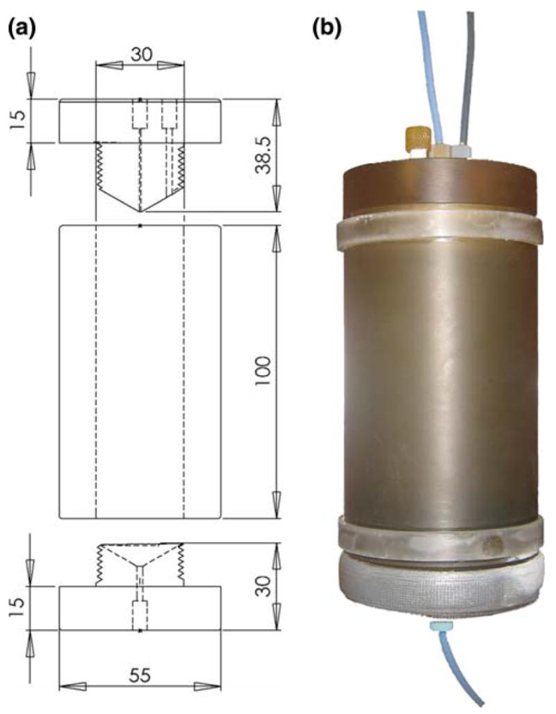
a Engineering drawing and b photograph of the laminar flow reaction chamber, to hold the hydrogenation reaction. The reactor is placed within the B1 and B0 coils. Dimensions are in mm
Low field NMR unit of the polarizer
The purpose of the low field NMR unit of the polarizer is to perform the spin order transfer sequence [8,9] right after the hydrogenation of the precursor molecule with parahydrogen. The coils for the static (B0) and r.f. (B1) field are therefore located around the laminar flow reaction chamber (Fig. 2), listed in (Table 2).
R.f. transmission: the saddle shaped B1 coil consists of two loops, each with six turns of gauge 22 magnet wire (10 cm × 20 cm), centered on an acrylic tube (O.D. = 10 cm, length = 35 cm) connected to the r.f. source by a BNC connector on top (based on a design from Promech lab AB, Malmö, Sweden). Two acrylic discs on the inside of the tube hold the reactor at iso-center of the B0 coil (Fig. 3).
Fig. 3.
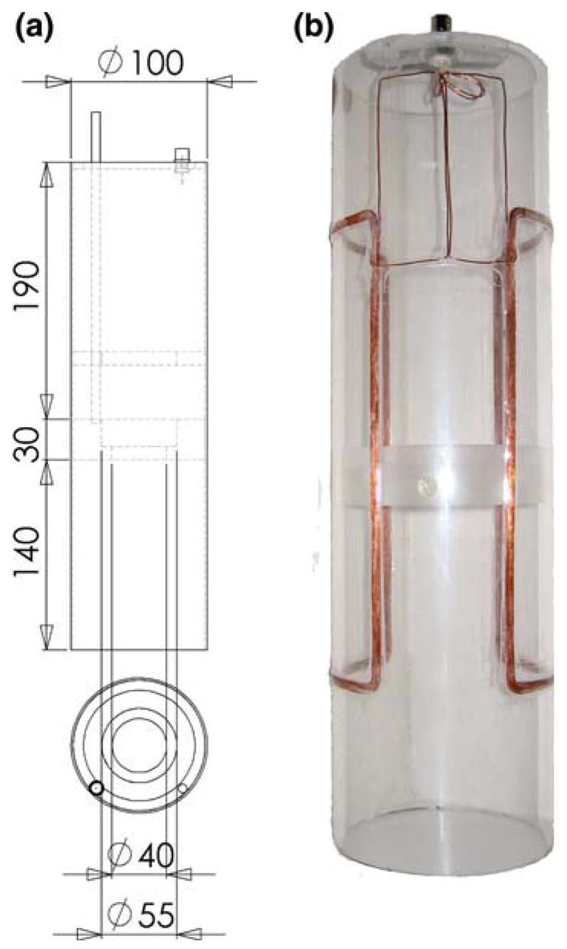
NMR unit of the PASADENA polarizer. a Engineering drawing and b photograph of B1 r.f. transmission coil. The reaction chamber (Fig. 2) is held in place by two mountings in the coil at the isocenter. The tip of the gauss meter probe, which is introduced from the top of the coil assembly is located outside the reaction chamber and close to isocenter. A BNC connector at the top of the NMR unit connects the cable delivering r.f. to the coil. Dimensions are in mm
Static magnetic field: B0 of the low field unit is generated by a solenoid coil that surrounds the r.f. transmission (B1) coil and the reactor (Fig. 4). It is driven by a precision DC power supply. The strength and stability is monitored by a Hall sensor, located in between the B1 coil and the reaction chamber. The Hall sensor is located near the bottom of the reactor, which coincides with the iso-center of the assembly. To improve the axial homogeneity of the coil, the solenoid is divided into three separate circuits (1:2:1 in length) with variable power resistors in parallel, to allow for independent adjustment of the current flow through each section (based on a design by Promech lab AB, Malmö, Sweden). A field map was performed to quantify the homogeneity of the static field. The axial component of the field was found to differ within the volume of the reactor by 0.022 mT (axial), and 0.011 mT (planar), at a field strength of 1.800 mT in the center of the volume. For hyperpolarization experiments, the strength of the static field was optimized on-site (1.763 mT) [7].
Fig. 4.

NMR unit of PASADENA polarizer. a Engineering drawing and b photograph of the solenoid coil for the generation of the static field (B0) and c photograph of the complete assembly of the parts described in Figs. 2 and 3. For improved homogeneity, the coil (shown in b) is constructed in three sections, which allow for individual control of the magnetic field (resistors in parallel to each section). The current is provided by a precision power supply, which is adjusted to the field determined with the gauss meter probe. Dimensions are in mm
Process control unit
A custom program on the LabView platform was developed, to control the valves for mechanized mixing, delivery and recovery of imaging reagents and application of the r.f. sequence in the correct order with precise timing. The event-sequence the r.f. pulse-sequence for the specific experiment are saved in separate files, and reloaded to the program as necessary.
R.f. transmission: the pulses necessary for the spin order transfer [8,9], were delivered from a synthesizer mounted in the polarizer cabinet. The pulses were digitized at an update frequency of 298.15 kHz, with four sample points per period at the 1H frequency (74.62 kHz), and >16 samples per period at the 13C frequency (18.76 kHz). The signal then passed through a 150 kHz low-pass filter to an amplifier and was applied to the un-tuned B1 coil. To facilitate r.f. calibrations, the amplitude of pulses is variable (Table 3). The r.f. optimization (center frequency, flip angle calibration) was performed as described elsewhere [7]. The amplitudes and pulse widths for 1H and 13C square inversion pulses were found to be 50 V and 115 μs for hydrogen and 25 V and 230 μs for carbon.
Valve control: the digital input/output channels of the digital to analog card (DAC) card were connected to relays to control opening and closing of the electromagnetic solenoid valves of the fluid system (Fig. 5, Table 3).
Fig. 5.

Process control unit of the PASADENA polarizer. The sequence of the PASADENA experiment (fluid control: valves 1–5, and spin order transfer B1) is controlled by one central computer (C). The static field (B0) and the temperature of the reaction compartment (Tp) are set by separate controllers (DC, Tc, respectively)
Parahydrogen generator
The complete parahydrogen generator unit is represented diagrammatically in Fig. 6, with details of the components listed in Table 4. A similar setup was published by Tam and Fajardo[10]. Since the amounts of parahydrogen in the gas tank of the polarizer are relatively small (7 L at 33 bar), and the US Safety regulations apply to hydrogen 400 L and above, there are no mandatory safety guidelines applicable to a PASADENA polarizer. Precise rules will vary by location and local regulations.
Fig. 6.
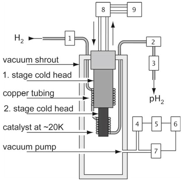
Schematic of a parahydrogen unit for the PASADENA polarizer. Commercially available hydrogen gas (25% parahydrogen, 75% orthohydrogen) is cooled to ~ 20 K and passed through a catalyst (granular ferric oxide, A) for >97% conversion to parahydrogen. The two stages of the cold head are surrounded by copper tubing packed with the catalyst: 1 Pressure regulator for incoming hydrogen; 2 flow meter; 3 flow controller; 4 pressure gauge; 5 pressure display; 6 relay; 7 vacuum pump valve; 8 helium compressor; 9 water cooler. A setup similar to the one published by Tam and Fajardo [10] is available commercially
Chemicals and auxiliary equipment
A clean chemistry laboratory with ventilation hood is essential, as is an exhaust route for the gaseous products of the polarizer itself, since, while parahydrogen presents little hazard, reagents, solvents and catalysts employed in PASADENA are associated with a variety of volatile toxins. For operation within a hospital, the local safety officer should be consulted. Table 5 lists the reagents, catalyst and solvents routinely employed.
The procedure for the preparation of the catalyst and the protocol of conducting a hyperpolarization experiment has been described briefly in published work from the GE/Amersham, Malmö, Sweden laboratory [8,9,11]. A brief overview is given here of the use of the polarizer in practice, more details can be found in [7]. The bisphosphine ligand, 1,4-bis-[(phenyl-3-propane sulfonate) phosphine] butane disodium salt, was dissolved in H2O/D2O to yield 2.5–3.0 mmol/L concentration followed by removal of oxygen by alternating exposure to vacuum and nitrogen connected via a manifold. A rhodium catalytic moiety was then introduced to the reaction mixture under nitrogen atmosphere as a solution of bis(norbornadiene)rhodium (I) tetrafluoroborate in acetone with 5% molar excess of the ligand with respect to rhodium. The resulting solution was vigorously shaken and acetone was removed under vacuum. For demonstration of hyperpolarization, 2–5 mg of the available, but toxic PASADENA reagent, hydroxyethyl acrylate 1-13C (99%), 1-13C, 2,3,3-d3 (98%) (HEA), is added to the catalyst solution under nitrogen atmosphere. The completed PASA-DENA solution of precursor and catalyst was drawn into a plastic syringe and connected to {V2} of the PASADENA polarizer, to allow the injection of a desired amount of imaging reagent for each experiment (3.5 mL unless otherwise noted). When prepared in these proportions, hydrogenation of the precursor was carried to completion until no residual precursor (HEA) could be detected by 13C NMR (not shown here).
Results
An assembled PASADENA polarizer is presented (Fig. 1), along with detailed description of all individual parts necessary (Tables 1, 2, 3, 4, 5; Figs. 2, 3, 4, 5, 6).
The events and time points for its smooth operation are presented in Table 6.
Manual preparation (Table 6): it is first necessary to ensure chemical and sanitary cleanliness by flushing all lines, valves and the reaction chamber with Millipore water and then to remove the surface moisture with nitrogen (step 1). Next, the desired amount of precursor-catalyst solution, prepared under nitrogen as described previously, is injected to the antechamber for heating (step 2).
Automated procedure (Table 6): the following steps (3–8) which include hydrogenation reaction; transfer of spin order from proton to third nucleus (13C, 15 N), the crucial step of hyperpolarization; delivery and detection of hyperpolarized substrate, are controlled by the computer. The duration of step 7 represents the maximum time (19 s) currently required to transfer the hyperpolarized reagent to the detection system. This reduces the time available for in vivo imaging and spectroscopy. It is anticipated that with further automation, this interval can be reduced to 5 s or less.
Following these steps, a high level of hyperpolarization (P ≈ 18%) of the test reagent was readily achieved in vitro (Fig. 7).
Fig. 7.
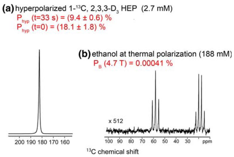
Quantification of the polarization achieved with PASADENA. 13C hyperpolarized spectrum of 2.7 mmol/L HEP 1-13C,2,3,3 -d3 at 4.7 T in vitro (a). Polarization of ~18% was achieved in this representative example. The inset spectrum shows a reference signal obtained from natural abundance ethanol; 13C concentration = 188 mmol/L per site (b). Note that the scale of the inset spectrum was magnified by 512 times
Discussion
The equipment described here has been in continuous use in this laboratory for 12 months, providing hundreds of effective hyperpolarizations with several different 13C enriched reagents. In the previous two years, the prototype briefly described by Axelsson (personal communication) was installed and operated in conjunction with a GE 1.5 T clinical MR scanner [12]. It is instructive to compare the new device with its predecessor, which was never in production and is no longer accessible.
A metallic nozzle which sprayed reagent and parahydrogen into the reactor, in the belief that hydrogenation requires a nebulized mixture of gas and liquid was removed. While the precise physics of the ‘spray’ were not explored further, simple mixing, without contact with metal appears to provide greater reproducibility in operation and removes a serious cause of contamination and obstruction to flow. Removal of all metallic parts in the liquid lines allow for a wider range of pH usage, as needed for certain biologically relevant PASADENA imaging reagents [13].
The power supply for the static field of the low field NMR unit was replaced, providing greater stability. A commercially available, more powerful pulse amplifier allowed for greater power and shorter pulses in the spin order transfer (SOT) sequence, so that the overall polarization became less sensitive to small changes in location and ambient magnetic fields.
Improved control over the chemistry of PASADENA, with mixing of reagents under nitrogen and better catalysis which results from a more reliable synthesis, removes a serious source of variability between successive ‘runs’ in the polarizer.
Automation, while still incomplete, removes the need for multiple operators during a hyperpolarization experiment, easing the path to effective in vitro and in vivo experimentation.
In summary, we believe that in addition to the critical point that a more detailed description is now provided, which would allow construction of further PASADENA polarizers, improvements have resulted in a more reliable instrument. The present instrument could be constructed by any competent workshop at reasonable cost. A number of features in the PASADENA polarizer described invite comments as the field of hyperpolarized NMR research evolves and applications diversify. This laboratory is particularly focused upon in vivo biological events with emphasis on metabolic transformations, which occur in the first hundred seconds after a substrate challenge. Future applications are certainly envisaged for the clinic where 13C MRS is already a valuable tool [14], albeit requiring longer acquisition times. For these applications as well as many others now being considered, we suggest a number of future advances, which are of immediate interest.
Sterility: sterility of the hyperpolarized agent, sterility of the entire apparatus and fluid lines with which reagents may come into contact before injection into an experiment animal, appears to be an important next step, once the issues of efficiency, repeatability and toxicity had been addressed. One approach may be to replace the present construction by one consisting of disposable lines, reactor and isolated valves. This is common practice in the clinical MRI environment where patient compatibility is clearly a greater consideration than cost. A second approach, less expensive and equally readily achieved with the present PASADENA-polarizer design is to substitute heat-resistant, autoclaveable components, or items which can be sterilized by exposure to ultraviolet or gamma ray. A second, dismountable laminar flow reaction chamber would allow for uninterrupted experimentation during sterilization of one reactor while the polarizer remains operational.
Stray field robustness: a systematic weakness of PASADENA in practice is the necessity for smooth and precise spin order transfer at low magnetic field, to produce a reagent with very short lived hyperpolarization (characteristic T1 of all of these methods lie between 20–70 s) detected within a high field superconducting small-animal, clinical or high resolution NMR. This problem is common to DNP where automated delivery procedures have been developed and are provided by the manufacturer (Oxford Instruments; GE Healthcare). For clinical use, a PASADENA polarizer most likely will need to be located within the r.f.-shielded room of the human MRI suite. Indeed, current clinical diagnostic MR angiography already employs magnet safe injectors capable of performing this function for hyperpolarized MRI, MRA and MRS. For the present PASADENA polarizer we envisage that magnetic field shielding, active shimming (gradient coils), passive shielding (metal) or other well-established methods will overcome much of the present difficulty, allowing the equipment to be positioned immediately adjacent to the NMR and simplifying the design of automated injection.
Catalyst removal: PASADENA, unlike DNP which uses an electron donor in form of toxic radical initiators, necessitates use of a ‘catalyst’ which ideally would be removed at the completion of hydrogenation, and before r.f. spin order transfer sequences have been completed. In the present construction, interposition of an ion exchange filter in the outflow (beyond Valve 5 in Fig. 1a, b) seems sufficient to remove the bulk (but not, perhaps all trace) of the rhodium based hydrogenation catalyst currently employed. Rigorous toxicity testing is therefore among the improvements necessary before clinical use could be contemplated. Ideas currently being explored include solid-support bound catalyst [15], ion exchange filter mounted as a column or even use of an alternative catalyst. The efficiency of the present rhodium norbornadiene complex is high but advances in catalysis seem bound, in the near future, to offer non-toxic alternatives with comparable efficiency.
Safety: in earlier versions of PASADENA polarizers the use of high gas pressures, high temperatures and volatile solvents presented many safety challenges. Most of these have become irrelevant as non-toxic, water-soluble reagents have been developed for PASADENA and as levels of hyperpolarization climb, permitting smaller volumes of very low, even physiological concentrations of injectable reagents to take the place of the massive doses (12 mL of 500 mM for example) of reagents dissolved in acetone which were previously employed. The minor hazard of small batches of hydrogen in a laboratory or clinic has been discussed.
Procedural deficiencies in PASADENA: why does this polarizer, in common with its predecessor still not achieve P = 1, or perfect hyperpolarization? We and other investigators [9] have speculated that shortcomings in the equipment, inefficiency in spin order transfer r.f. sequences, inaccuracy of low field calibration, impurities in the chemicals, unknown J-couplings, local field inhomogeneity due to metal ‘injection ports’, valves and so on could all distort the result of this finely tuned process. A simple intervention such as shut down of unnecessary electronics during r.f. (normally closed valves) would reduce field distortion attributed to valves. Future improvements in the present design can be anticipated. We consider the use of quality assurance procedures will significantly improve the degree of polarization and its reproducibility. A Quality Assurance (QA) protocol suited to this advance is described elsewhere [7].
Conclusion
A semi-automated PASADENA polarizer capable of delivering 2.5–5 mL of highly polarized biological 13C imaging reagents in less than 1 min, and of repeated delivery every 5–8 min, is described. Tailored transfer sequences make this equipment versatile for a variety of biomolecules capable of undergoing reaction with parahydrogen necessary for effective PASADENA. Together these descriptions simplify the technology for routine liquid state generation of hyperpolarized molecules for 13C and 15N subsecond imaging and spectroscopy in vivo and advance the day when such technologies find clinical utility.
Acknowledgments
Rudi Schulte Research Institute of Santa Barbara generously funded construction and supported research with PASA-DENA. We also thank the following for generous funding: NIH 1R21 CA118509 (PB), NCI 5R01CA122513 (BDR), NIH 1R01NS048589 (JBH, BDR), Rudi Schulte Research Institute (RSRI) (EYC, JBH), James G. Boswell Fellowship (PB, EYC), American Heart Association (PB), American Brain Tumor Association (PB), Tobacco Related Disease Research Program (PB), NARSAD (KH), Cancer Research and Prevention Foundation (EYC). We thank Dr. Daniel P. Weitekamp, Valerie A. Norton and Raymond A. Weitekamp for assistance with instrumentation. We also thank Dr. William Opel for support of PASADENA program at HMRI, Dr. Scott Ross for providing convenient access to high resolution solution NMR facility at Caltech. JBH thanks Drs. Peter Bachert and Wolfhard Semmler (German Cancer Research Center, DKFZ, Heidelberg, Germany) for PhD supervision. PB and BDR thank Drs. Oskar Axelsson, Haukur Johannesson and Magnus Karlsson for advice and training with the parahydrogen polarizer, in Malmö and provided for this work under loan agreement between HMRI and GE Healthcare, established by Dr. Klaes Golman.
Appendix
PTFE tubing, OD/ID/WT: 1/8, 1/16, 1/32, Nalgene, NY, USA.
Two-ways rocker valve, mod. 6126 (id. 431568, for liquids), Buerkert Fluid Control Systems, Indelfingen, Germany.
Addition to 6126 by Promech lab AB, Malmö, Sweden.
Solenoid valve, mod. H22G9DGV (for gases), Peter Paul Co., CN, USA.
Mod. CN132, Omega Engineering, CN, USA.
Mod. 814 Syrelec, Crouzet, TX, USA.
BD, Franklin Lanes, NJ, 07417, USA.
Mod. PXI 1042, PXI 8331, PXI 6251, National Instruments, TX, USA.
Mod. 8522 TX, Onkyo, USA.
Mod. 3200, Krohn Hite, USA.
Mod. TDS 3012 B 100 MHz 1.25 Gs/s, Tectronix, USA.
Generic.
Mod. 3615A, Agilent, USA.
Gaussmeter 450 with axial probe MMA 2508 VH, Lake shore, USA.
LabView (V. 8.0), National Instruments, TX, USA.
Mod. USB 6501, NI, TX, USA.
Mod. ER-16, NI, TX, USA.
Mod. B51907000 6130 cold head assembly, Edwards, MA, USA.
Active pirani gauge, APG M NW 25 ST/ST, PN: D0217200 SN: 02723484.
Generic, S.C.B., Herrmann-Cossmann-Str. 19, D-41472 Neuss, Germany.
3.0 kW He cryodrive, Edwards, MA, USA.
Mod. RV3, with oil mist filter EMF 10, Edwards, MA, USA.
Mod. LCPV2 5 EKA, Edwards, MA, USA.
Needle valve HAKE 1315G4s 5000PSI/345 bar 1 0553, set 4.5.
Generic, 240 V.
Mod. AGD, set to ~ 2× 10⁻⁴ bar, Edwards, MA, USA.
Mod. Neslab Merlin M150, Thermo Fischer Scientific, MA, USA.
“Instrumentation-quick-connect” (SS), Swagelok, OH, USA.
Regulator 250 bar to 68 bar, Advanced specialty gas equipment, NJ, USA.
1/4″ copper/1/4″ SS generic, 7RSW SAE 100 R7-4 1/4 2750 PSI swagelok, OH, USA.
Mod. 7101 043001A, King Instruments, CA, USA.
1/4″ copper tubing, generic.
Ionex-Type O-P catalyst (hydrous ferric oxide), Molecular products, CO, USA.
7 L volume, M25×2 150, CBM produkter AB, Box 47, 131 06 Nacka, Sweden, or P2795z, Luxfer, CA, USA.
Fumaric acid, 1-13C (99%), 2, 3 -d2 (96%), Cambridge Isotope Laboratories, MA, USA.
Hydroxyethyl acrylate 1-13C (99%), 2, 3, 3, -d3 (98%), Isotech, Sigma–Aldrich, MO, USA.
Bis(norbornadiene)rhodium(I) tetrafluroborate, catalog number 45-0230, CAS 36620-11-8, >96%, Strem Chemicals, MA, USA.
1, 4-bis[(phenyl-3-propanesulfonate) phosphine] butane disodium salt, Q36333, Isotech, Sigma–Aldrich, MO, USA.
Generic.
References
- 1.Gillard JH, Waldman AD, Barker PB. Clinical MR neuroimaging: diffusion, perfusion and spectroscopy. Cambridge University Press; New York, NY: 2005. [Google Scholar]
- 2.Albert MS, Cates GD, Driehuys B, Happer W, Saam B, Springer CS, Wishnia A. Biological magnetic-resonance-imaging using laser polarized Xe-129. Nature. 1994;370:199–201. doi: 10.1038/370199a0. [DOI] [PubMed] [Google Scholar]
- 3.Ardenkjaer-Larsen JH, Fridlund B, Gram A, Hansson G, Hansson L, Lerche MH, Servin R, Thaning M, Golman K. Increase in signal-to-noise ratio of >10,000 times in liquid-state NMR. Proc Natl Acad Sci USA. 2003;100:10158–10163. doi: 10.1073/pnas.1733835100. [DOI] [PMC free article] [PubMed] [Google Scholar]
- 4.Bowers CR, Weitekamp DP. Para-hydrogen and synthesis allow dramatically enhanced nuclear alignment. J Am Chem Soc. 1987;109:5541–5542. [Google Scholar]
- 5.Kuhn LT, Bargon J. Transfer of parahydrogen-induced hyperpolarization to heteronuclei. Top Curr Chem. 2007;276:25–68. [Google Scholar]
- 6.Golman K, Axelsson O, Johannesson H, Mansson S, Olofsson C, Petersson JS. Parahydrogen-induced polarization in imaging: subsecond C-13 angiography. Magn Reson Med. 2001;46:1–5. doi: 10.1002/mrm.1152. [DOI] [PubMed] [Google Scholar]
- 7.Hövener JB, Chekmenev EY, Norton VA, Harris K, Perman WH, Weitekamp DP, Bhattacharya P. Quality assurance of PASA-DENA hyperpolarization for 13C biomolecules. Magn Reson Mater Phy. 2007 doi: 10.1007/s10334-008-0154-y. in press. [DOI] [Google Scholar]
- 8.Goldman M, Johannesson H. Conversion of a proton pair para order into C-13 polarization by rf irradiation for use in MRI. C R Physique. 2005;6:575–581. [Google Scholar]
- 9.Goldman M, Johannesson H, Axelsson O, Karlsson M. Design and implementation of C-13 hyperpolarization from para-hydrogen for new MRI contrast agents. C R Chimie. 2006;9:357–363. [Google Scholar]
- 10.Tam S, Fajardo ME. Ortho/para hydrogen converter for rapid deposition matrix isolation spectroscopy. Rev Sci Instrum. 1999;70:1926–1932. [Google Scholar]
- 11.Goldman M, Johannesson H, Axelsson O, Karlsson M. Hyperpolarization of C-13 through order transfer from parahydrogen: a new contrast agent for MRI. Magn Reson Imaging. 2005;23:153–157. doi: 10.1016/j.mri.2004.11.031. [DOI] [PubMed] [Google Scholar]
- 12.Bhattacharya P, Harris K, Lin AP, Mansson M, Norton VA, Perman WH, Weitekamp DP, Ross BD. Ultra-fast three dimensional imaging of hyperpolarized C-13 in vivo. Magn Reson Mater Phys. 2005;18:245–256. doi: 10.1007/s10334-005-0007-x. [DOI] [PubMed] [Google Scholar]
- 13.Chekmenev E, Hövener JB, Norton VA, Harris K, Batchelder LS, Bhattacharya P, Ross BD, Weitekamp DP. PASADENA hyperpolarization of succinic acid for MRI and MRS. J Am Chem Soc. 2008;130:4212–4213. doi: 10.1021/ja7101218. [DOI] [PMC free article] [PubMed] [Google Scholar]
- 14.Ross B, Lin A, Harris K, Bhattacharya P, Schweinsburg B. Clinical experience with C-13 MRS in vivo. NMR Biomed. 2003;16:358–369. doi: 10.1002/nbm.852. [DOI] [PubMed] [Google Scholar]
- 15.Bouchard L, Burt S, Anwar M, Kovtunov K, Koptzug I, Pines A. NMR imaging of catalytic reactions in microreactors with the use of para-hydrogen. Science. 2008;319:442–445. doi: 10.1126/science.1151787. [DOI] [PubMed] [Google Scholar]