Abstract
Titanium alloys are widely used in total-joint replacements due to a combination of outstanding mechanical properties, biocompatibility, passivity and corrosion resistance. Nevertheless, retrieval studies have pointed out that these materials can be subjected to localized or general corrosion in modular interfaces when mechanical abrasion of the oxide film (fretting) occurs. Modularity adds large crevice environments, which are subject to micromotion between contacting interfaces and differential aeration of the surface. Titanium alloys are also known to be susceptible to hydrogen absorption, which can induce precipitation of hydrides and subsequent brittle failure. In this work, the surface of three designs of retrieved hip-implants with Ti-6Al-4V/Ti-6Al-4V modular taper interfaces in the stem were investigated for evidence of severe corrosion and precipitation of brittle hydrides during fretting-crevice corrosion in the modular connections. The devices were retrieved from patients and studied by means of scanning electron microscopy (SEM), x-ray diffraction (XRD) and chemical analysis. The surface qualitative investigation revealed severe corrosion attack in the mating interfaces with evidence of etching, pitting, delamination and surface cracking. In vivo hydrogen embrittlement was shown to be a mechanism of degradation in modular connections resulting from electrochemical reactions induced in the crevice environment of the tapers during fretting-crevice corrosion.
Keywords: titanium alloy, crevice corrosion, pitting, crack, hydrogen embrittlement
1. Introduction
In spite of its protective surface oxide layer, titanium and its alloys are not immune to corrosion attack when placed in contact with body fluids. Titanium alloys are susceptible to corrosion in vivo and it has been documented that these alloys can experience several forms of corrosion in the presence of mechanical loading. Pitting, crevice corrosion, and mechanically assisted corrosion (MAC) are forms of corrosion that can damage medical devices1. Corrosion of titanium hip-implants has also been associated with modularity of different designs. Fretting and corrosion at the head-neck junctions have been explored in several retrieval studies showing that severe corrosion can take place at the modular connections2–7. According to Gilbert et al.7, 16 to 35% of the pool of retrieved femoral hip prostheses (148 total) presented evidence of moderate to severe corrosion in head-neck taper connections. Collier et al. found that 17 of 30 mixed-metal femoral prostheses presented time-dependent evidence of corrosion3 in which the crevice provided between the head and neck connection functioned as corrosion sites due to the development of a stagnant aqueous environment at these interfaces2. On the other hand, the performance and corrosion mechanisms occurring on the stem/sleeve connections of modular body femoral components are not well characterized or understood. Modular body femoral components have tapers where both male and female sides consist of Ti-6Al-4V for the most part. The stem/sleeve connection presents a larger crevice geometry and angular mismatch between the taper on the male (stem) and female sleeve sides, which contributes to relative motion (fretting) at these modular connections8–12. Brown et al.13 has demonstrated with early in vitro studies that relative motion between highly resistant medical alloys can lead to fretting corrosion and release of metal ions. The combined effect of cyclic loading and fretting motion will result in accelerated abrasion of the oxide film covering the titanium surface, which consequently leads to exposure of the bulk metal to active dissolution and repassivation reactions14. Titanium crevice corrosion results from differential aeration and continued acid concentration developed in the restricted volumes within the crevice13,15–17. Therefore, the combination of a large crevice environment, which may produce significant changes in local solution chemistry, and fretting can lead to a series of corrosion events in Ti/Ti taper regions that have not yet been documented.
Titanium alloys are also known to have great affinity for hydrogen in different environments, being susceptible to hydrogen attack even at residual concentration levels. The interaction of hydrogen with titanium alloys varies with temperature, microstructure, presence of impurities, level of surface stress and material processing history18–22. Upon the interaction of the first traces of hydrogen atoms with the crystal lattice an effect generally classified in the literature as hydrogen embrittlement can occur18–20. Embrittlement is characterized by degradation of the mechanical properties of titanium alloys such as decrease in ductility, decrease in tensile strength, decrease in the number of fatigue load cycles to failure and increase in the rate of crack propagation18,21–24. As the concentration increases, hydrogen-containing phases other than the bulk solid solution can develop and at critical hydrogen concentrations the generated stresses can relax by producing dislocations, grain rotation, microvoids and hydrogen induced cracking (HIC)19,21. For α-β alloys (Ti-6Al-4V) the solubility of hydrogen is observed to be several orders of magnitude higher in the β-phase than in the α-phase22. This effect is related to the more open lattice space of the β-phase (BCC) that allows for faster diffusion and then higher solubility than that observed for the hexagonal close-packed structure (HCP) of α-titanium. Gutelmacher and Eliezer22 showed that for Ti-6Al-4V alloy the hydrogen solubility in the α-phase is extremely small resulting in the formation of titanium hydride at very low hydrogen concentrations.
In this work, in vivo incidence of severe corrosion and hydrogen embrittlement on the surface of the Ti-6Al-4V modular stem hip-replacements is investigated. Qualitative and quantitative analysis were performed by means of SEM, x-ray diffraction and chemical analysis in order to verify precipitation of hydrides and hydrogen induced effects in the crevices of the modular tapers. To the best of our knowledge, hydrogen embrittlement of Ti-6Al-4V has not been previously reported in retrieved orthopaedic implants.
2. Materials and Methods
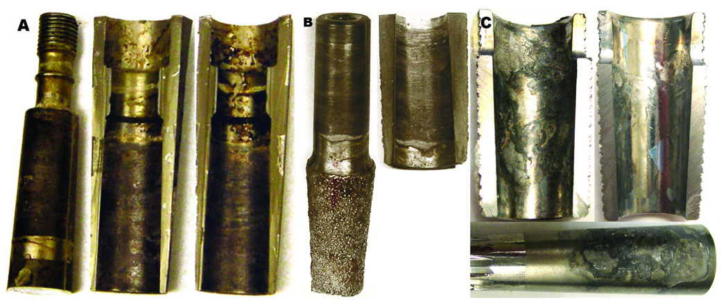
Samples from three retrieved, cementless, modular body femoral hip prostheses from a larger study involving thirty three retrieved Ti-6Al-4V implants25 were chosen for analysis. These three were specifically selected because the interfaces of the components presented evidence of severe corrosion and deposition of corrosion debris and represented the most severe examples of the pool of thirty three implants examined. The implants consisted of modular connections in the stem region (stem/sleeve junction) where both interface sides are Ti-6Al-4V alloy. Totally, ten sectioned parts were examined from the three implants for evidence of severe corrosion at the connection between the male taper of the proximal stem and the female taper of the sleeve. The three designs studied included one ZMR Porous Revision Hip Component (designated “Z”, Zimmer Inc., Warsaw, IN), one Mallory-Head Modular Calcar Revision (designated “M”, Biomet Inc, Warsaw, IN) and one Sivash-Range of Motion (S-ROM) (designated “S”, DePuy Johnson & Johnson Inc., Warsaw, Inc). The three components were retrieved due to pain and/or infection-related causes after periods of time from 1 to 27 months after surgery. Detailed clinical data and surface damage scores for the stem tapers and sleeve samples are given in Table 1. Figure 1 illustrates the samples used in this study emphasizing the degree of degradation present in the contacting interfaces. As shown in Fig. 1, two of the designs have standard modular connections (Z and M) while the S taper is a sleeve that fits over top of the stem.
Table 1.
Clinical data for the retrieved implants used in this study
| Design | Reconstruction | Duration (months) | Reasons removal | Surface damage scorea | |
|---|---|---|---|---|---|
| Stem taper | Sleeve | ||||
| Z | Revision | 22 | Infection | 4 | 4 |
| M | Revision | 1 | Infection | 3 | 3 |
| R | Primary | 27 | Pain | 4 | 4 |
corrosion scores: 4: severe corrosion (> 30% of the area is affected) and 3: moderate (about 30% of the area is affected). Adopted from Goldberg et al.8
Fig. 1.
Digital images of retrieved samples. (a) Z hip system showing the male taper and proximal female tapers (lateral and medial half-sleeve, respectively). (b) M system showing the male taper and proximal female, portions, respectively, of the femoral stem. (c) S component showing the proximal female and male tapers, respectively.
The morphology of corrosion and identification of regions with brittle appearance and HIC was documented with scanning electron microscopy (SEM – JEOL 5600) using both secondary and backscattered electron imaging. Prior to the analysis, the samples were subjected to gradual ultrasonic cleanings for 25 minutes starting with a superficial removal of the deposits with distilled water, distilled water and detergent (Enzyme-Active Powdered Detergent, Terg-A-Zyme – Alconox, Inc.) and finally applying a more intense cleaning with absolute ethyl alcohol.
The formation of hydride phases on the severely corroded samples was examined by x-ray diffraction (XRD) analysis with Cu Kα radiation of wavelength λ=1.54 Å in the 2θ angle range from 10° to 70° and operated at 40 kV and 40 mA. For the diffraction experiments, the retrieved samples were cut in thin slices (1.5 cm length × 1.0 cm width × 0.1 cm thickness). Prior to the analysis, the samples were gently polished with 600-grit SiC paper and ultrasonically washed in ethanol solution for 20 minutes.
The concentration of hydrogen in the taper samples was measured by chemical analysis performed at commercial laboratories. Two different techniques were used to measure hydrogen levels, low resolution and high resolution methods. The low resolution analysis (Quantitative Technologies, Inc., QTI, Whitehouse - NJ) applies combustion for H analysis in a pure oxygen environment where the gases are mixed and separated by frontal chromatography (Perkin Elmer - 2400 Series II CHNS/O). The high resolution analysis was performed with the samples where the initial results were below the limit of detection of the combustion technique (> 0.10 wt.% or 7 at.%). The high resolution chemical analysis was performed using Prompt-Gamma Neutron Activation Analysis, PGNAA, (Elemental Analysis, Inc., Lexington - KY). This method is based on the detection of prompt γ-rays emitted from nuclei in an excited state during irradiation. The energy of the γ-ray indicates the isotope present and the intensity gives the isotope concentration in the material. The detection limit of the PGNAA technique for hydrogen is about 1 ppm (0.0001 wt.%). The taper samples submitted for analysis were sectioned from the corroded regions with dimensions in average 1 cm (width) × 1 cm (length) × 0.5 cm (thickness) for the female tapers and 1 cm (diameter) × 0.5 cm (thickness) for the male taper samples. Control samples, sectioned from distal regions in the stem (far from the female taper), with no morphological corrosion features, damage or debris deposition were also submitted to high resolution analysis for comparison with the concentrations measured in the tapered interfaces. The samples were ultrasonically rinsed in ethanol and water solution three times after sectioning.
A transverse microscopic section analysis was performed for each of the samples presenting multidirectional cracking and brittle regions. The samples were cut transversely to the corroded surface and the section was made through regions presenting severe cracking and microstructural attack. For the microscopic analysis, the sectioned surfaces were ground up to 600-grit and polished with an alumina in water solution (0.3 µm). The polished surfaces were subjected to ultrasonic cleaning for 25 minutes with detergent for removal of residues and dried in air. The samples were subsequently etched with Kroll’s reagent (0.2% HF, 1.5% HNO3 in water for about 10 seconds) to reveal the microstructure. In order to verify the composition of the “debris layer” revealed with the transverse section analysis of the Z component, x-ray compositional microanalysis (WDS, Wavelength Dispersive Spectrometry) was performed using a JEOL JXA 8600 Superprobe. WDS was used to identify and map the chemical composition of the surface region in cross-sections. The sectioned interfaces were scanned for x-rays associated with the elements titanium, oxygen, aluminum and vanadium.
3. Results
3.1. SEM Observations – Severe Corrosion in Modular Tapers
The extent and nature of the damage was similar for the mating interfaces for each design in the study (see Fig. 1). The taper interfaces in the stem region introduce a larger crevice area, which is subjected to micromotion and fretting. Fretting corrosion of modular tapers has been observed with in vitro26,27 studies with titanium alloys; however these studies have not documented the extent of the corrosion effects observed in this retrieval study. Fretting scars and corrosion damage at the taper interfaces were observed over most of the taper areas in all three devices analyzed. In many regions, signs of fretting produced by the micromotion between the contacting interfaces were obliterated indicating increased metallic dissolution (data not shown).
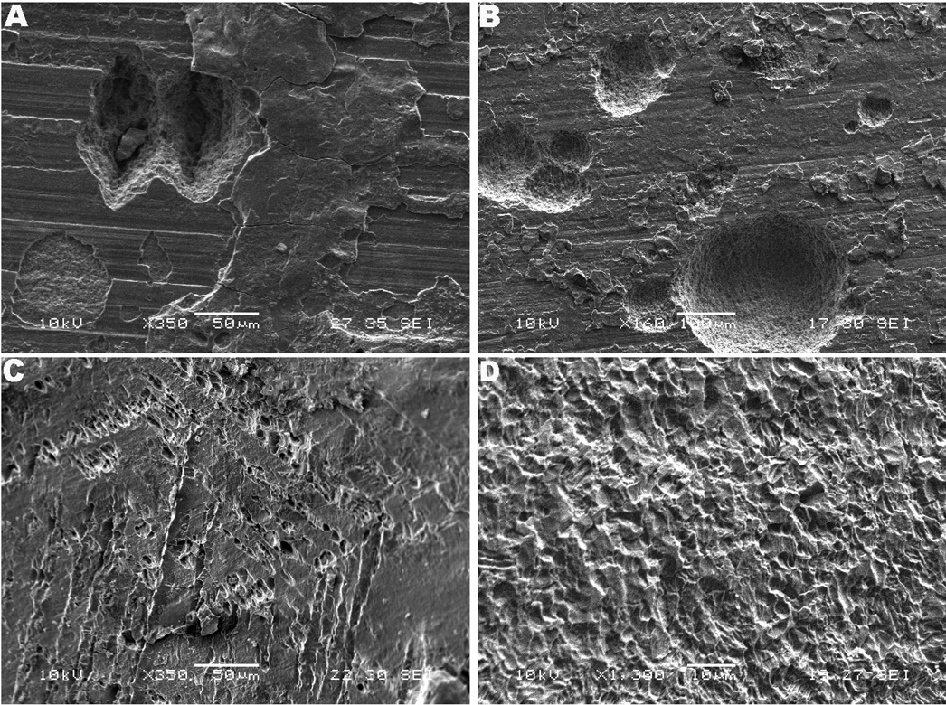
A remarkable degree of pitting attack was observed in all three modular interfaces as shown in Fig. 2. The Z component, Figs. 2a and 2b, and S component, Figs. 2c, both showed significant pitting attack, whereas for the M components pitting was much less than in the other two devices appearing within regions presenting crystallographic etching, as shown in high magnification in Fig. 2d. The pitting typically revealed microstructural features, as shown in Figs. 2c and 2d or appeared inside regions with delamination, cleavage or cracking patterns, as shown in Fig. 3. For the Z component the nucleation of large and deep pits indicated a mode of stable pitting propagation occurring in the taper crevice. This effect is likely a result of shifts in potential to more cathodic values occurring during mechanical abrasion of the oxide film. The pits occurred individually or in clusters in both stem and sleeve interfaces ranging up to several hundred micrometers. Figures 2a and 2b illustrate the extent of pitting attack in the interface of the Z modular system. In particular, Figure 2b shows pitting propagation up to 250 µm in diameter, a result not expected to happen with titanium due to its relative resistance to pitting attack and contradictory to earlier observations that below the pitting potential stable pits do no develop28. Considering titanium does not present a transpassive region, a second mechanism for pitting attack was hypothesized to occur when the voltage drops to the passivating potential (active to passive boundary region). This mechanism is facilitated in the taper crevices where the oxide damage leads to voltage drops approaching the active region. Figure 2c shows the pitting patterns observed with the S component. Similar to the Z component, pitting of the modular stem and sleeve was present; however the pitting patterns in the sleeve interfaces were very particular. The pits followed the microstructure revealed by etching of the crystallographic planes, presenting a more dimple-like morphology. This result may have been induced by the microstructural modification to which the sleeves of the S component were subjected, the so called transformed-β or Widmanstatten structure.
Fig. 2.
SEM micrographs of pitting attack. (a) Z component (medial proximal female taper, 350×) and (b) lateral proximal male taper (160×). Note the dimensions (in average large than 100 µm) and depth of the nucleating pits. (c) S component (proximal taper, 350×). Etching of the surface revealing the crystallographic planes (hexagonal structure). It is interesting to notice the pitting pattern (voids pattern) following the plane. In the Widmanstatten microstructure voids are observed to be initiated at α/β interface or boundary α phase. (d) M component (posterior medial proximal female taper, 1,360×). Note etched α-grains and selective dissolution of β.
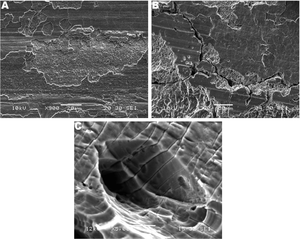
Fig. 3.
SEM micrographs of cracking morphology. (a) M component (anterior medial proximal female taper, 900×). Notice the cracking of the top surface layer and region with microstructure exposure by crack propagation. (b) Z component (lateral proximal female taper, 500 and 330×, respectively). Interpenetrating cracks were observed in several regions of the stem/sleeve taper samples. (c) S component (lateral proximal female taper, 5,000×). High magnification showing cracks following the microstructure in which the cracks were penetrating into the microstructure, also propagating out from the pit.
Corrosion-induced cracking on the taper interfaces was another major feature typically present on the corroded surfaces of the stem/sleeve interfaces. Fretting-corrosion fatigue cracking is likely to occur as a result of cyclic loading and fretting motion interacting with the crevice corrosion reactions. However, the cracking morphology did not appear to have been initiated by a corrosion fatigue process. Figure 3 shows the cracking patterns observed on the sleeve interfaces of the three implants. The M component presented cracking of the most superficial layers, shown in Fig. 3a, while the S sample interfaces presented interpenetrating cracks on the corroded sleeve (lateral proximal female taper) following the Widmanstatten microstructure, as illustrated in Fig. 3c. Particularly, the cracking on the Z interfaces, both on the stem and sleeve, presented microstructural and interpenetrating morphology revealing cleavage of the bare material and brittle failure, as shown in Figs. 3b and 3c. The patterns shown in Fig. 3 include needle-like precipitates (Fig. 3a) and interpenetrating cracks (Figs. 3b, c and d) and are morphological evidence of precipitation of brittle phases in the material (hydride formation), which can lead to HIC. This propagation mode and cleavage are likely a result of residual stresses development caused by lattice expansion during the hydrogen embrittlement process and/or cleavage of brittle phases precipitated in the material
3.2. SEM Observations – Evidence of Hydrogen Induced Cracking (HIC) and Brittle Regions
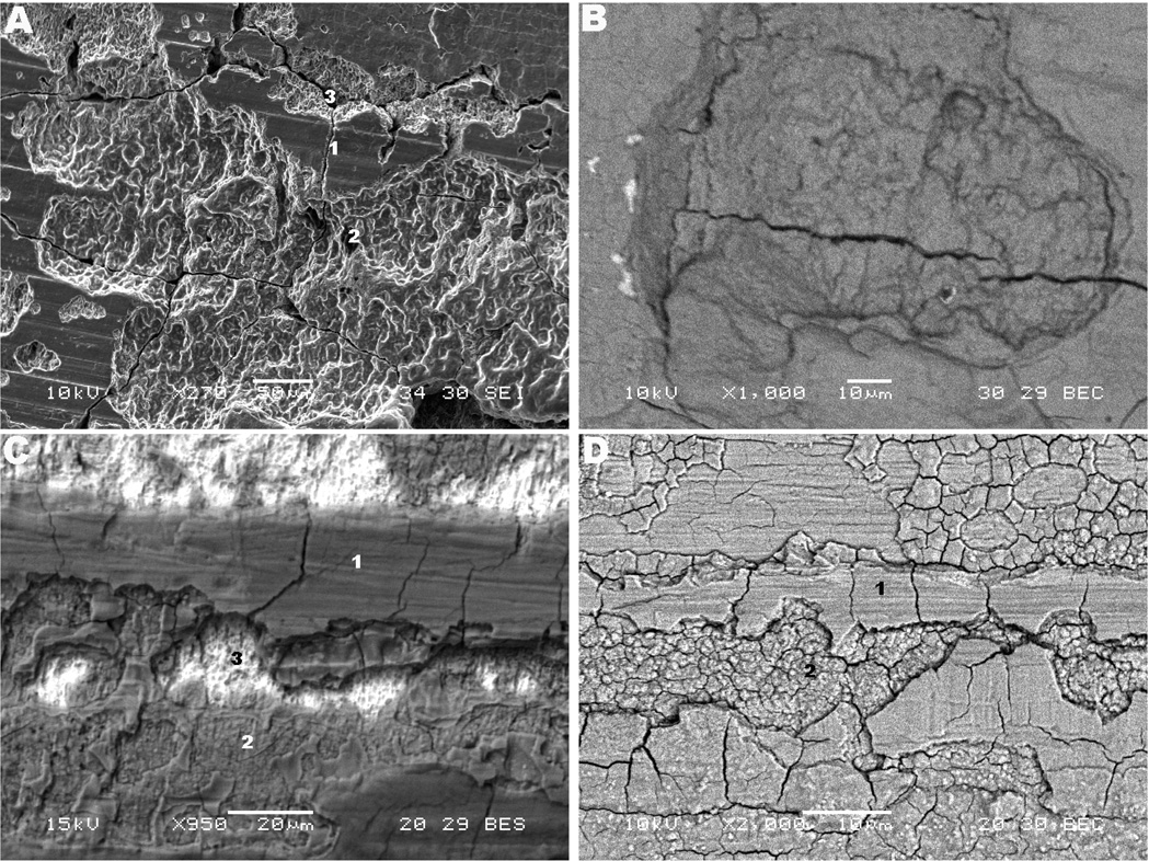
The presence of hydrogen embrittlement occurring in the modular tapers was first hypothesized by the observation of regions with brittle appearance and with particular crack propagation mode, as previously shown in Figs. 3a and 3b. Figure 4 shows regions with delamination, cracking in different layers and corrosion patterns observed in the three implants. Figure 4a shows a high magnification SEM image where cracking in three different layers exposed the microstructure. Several regions in the tapers of the Z component, including the femoral stem, presented cracking of the top layer (indicated by number 1 in Fig. 4a), intermediate layer (number 2) and microstructure (number 3). It is interesting to note the unbranched morphology of the cleaved regions (see Fig. 4a). Figure 4c shows a backscattered SEM image of an example of delamination in three layers observed for the M component. The regions with the three layered structure presented cracking of the top and intermediate layers (grooved portions), while the underlying microstructure (bright region) remained intact in most of the cases observed. This morphology was frequently observed with other taper samples from the M component showing delamination of the surface with the following structure: 1. top layer (debris, oxide layer and biological material); 2. intermediate layer (granular layer – spherical particles present); 3. alloy substrate (presenting pitting attack within the microstructure – bright region). Figures 4b and 4d show high magnification backscattered mode SEM micrographs of the cracked structure of the Z and M components, respectively. The former case shows deep interpenetrating cracking, while the latter presents cracking of the most superficial layers. Similar to Fig. 4c, the three-layered structure was observed for the stem of the S component (cracking of the top and intermediate layers); however this component did not present the three-layered delamination in the sleeve (female taper) interface.
Fig. 4.
SEM micrographs of cracking patterns in the three designs and structure of delamination. (a) and (b) Z lateral proximal female taper (270×) and medial proximal female taper (1,000×), respectively. (c) and (d) M posterior medial proximal female taper (950×) and anterior medial proximal female taper (2,000×), respectively. In the Figures, the features numbered as 1, 2, 3 represent top layer (metal surface), intermediate layer and microstructure, respectively.
3.3. X-ray Diffraction – Identification of Hydride Phases
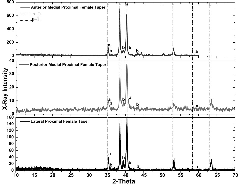
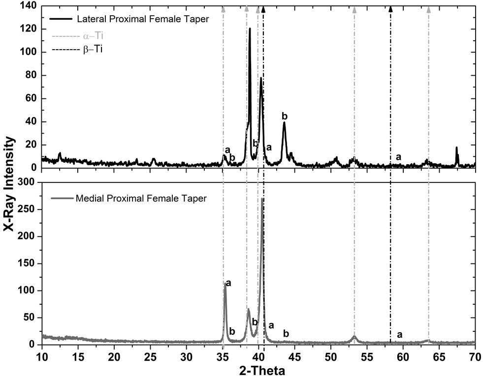
In order to verify the hypothesis of precipitation of hydride phases in the material during fretting-crevice corrosion, which may have led to the cracking patterns previously illustrated, x-ray diffraction (XRD) experiments were performed. XRD was used to identify the precipitation of hydride phases on the surface of the retrieved taper samples by the observation of characteristic peaks. The diffraction peaks of hcp titanium (α-Ti) are found at the angles 2θ = 35°, 38.4°, 40.2°, 53° and 63°, and for bcc titanium (β-Ti) at 2θ = 40.3° and 58.1° in the diffraction patterns of the following figures. The γ-hydride peaks (γ-TiH) are assigned at the diffraction peaks at 2θ = 36°, 39.5° and 43°, while the δ-hydride peaks (δ-TiH1.5–1.99) are at 2θ = 35.4°, 41° and 59.3°. Other peaks are also observed for 2θ > 70° (not reported). It should be pointed out that the most representative peak for titanium hydride is located at 2θ = 39.5° (γ-TiH).
Figure 5 shows diffraction patterns for the M component samples set. In the patterns “a” and “b” represent the peaks corresponding to δ-TiH1.5–1.99 and γ-TiH hydrides, respectively. The results show a good correspondence with γ-TiH at 2θ = 39.5° in the three samples analyzed. The δ-TiH1.5–1.99 peak at 35.4° overlaps with the α-Ti (2θ = 36°) being difficult to qualitatively judge the formation of δ-TiH1.5–1.99 at this site in the lattice. At 2θ = 41° the peak corresponding to δ-TiH1.5–1.99 is close to the assigned peak for β-Ti. Assigned peaks for γ-TiH are clearly observed at 2θ = 39.5° and 43° for the anterior medial proximal female taper (top panel). For the posterior medial (middle panel) and proximal female taper (lower panel) the γ-TiH peak is evident at 2θ = 39.5°. Although the regions observed with XRD may not be exactly the same demonstrated by the SEM micrographs, since it is difficult to state precisely if the x-ray beam hit the specific region of interest, the results indicate that the surface morphology with the characteristic needle-like structure and amorphous spheres are strong evidences of hydride formation on the microstructure of the M device. The diffraction patterns for the Z components did not show the hydride peaks observed for the other designs (data not shown). Although the SEM analysis showed highly corroded regions with morphological evidence of hydrogen-induced cracking, the XRD analysis did not indicate evidence of hydride precipitation at the assigned peak 2θ = 39.5°. The concentration of hydrogen is lower in these samples (see chemical analysis) but still high enough to possibly cause the hydrogen-induced cracking pattern. Figure 6 shows the diffraction patterns for the S component. The results showed the presence of the γ-TiH peak at 2θ = 39.5 ° and 43° for the corroded sample (lateral proximal female taper). The 43° peak was intense in comparison to the alloy phase peaks in the pattern; therefore, the possibility of oxide influence or other elements was investigated but could not be verified considering this peak was not observed with the other sample (mild corrosion). On the other hand, no hydride peaks were identified for the mild-corroded sample (medial proximal female taper). Also, it is interesting to note the intensification of the β-Ti peak at 2θ = 40.5° in relation to the pattern of the corroded side. This result is expected since the microstructure of the S component showed continuous and thick β-lamellae, which was mostly undamaged for the medial proximal female taper and therefore, increasing the hydrogen terminal solubility in this region.
Fig. 5.
X-ray diffraction patterns for the M component. a and b represent the peaks corresponding to δ-TiH1.5–1.99 and γ-TiH hydrides, respectively. The dotted lines mark the peaks for the α and β-titanium phases.
Fig. 6.
X-ray diffraction patterns for the S component. a and b represent the peaks corresponding to δ-TiH1.5–1.99 and γ-TiH hydrides, respectively. The dotted lines mark the peaks for the α and β-titanium phases.
It is important to mention that some of the hydride peaks overlap with peaks assigned to oxides. The main hydride peak, 39.5°, is also assigned to TiO2 (rutile) and the peak at 43° is assigned to TiO oxide. The combined effect of oxidation and mechanical mixing leading to wear of Ti-6Al-4V in fretting areas has been reported in the literature29. However, the possibility of crystalline oxide present (which must have sufficiently large crystal size and crystallinity to be detected by x-rays) in the diffraction patterns is weakened by the fact the Z component did not present any of these oxide peaks and also because multiple observations (SEM, x-ray, elemental analysis in low and high resolutions) have shown evidence of hydride precipitation in the M and S components. In addition, several studies have shown precipitation of γ-hydride in titanium assigning the peak 2θ = 39.5° as titanium hydride when the concentration of hydrogen in the material is increased23,24,30.
3.4. Elemental Analysis – Hydrogen Concentration Measurements
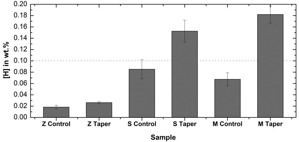
Figure 7 shows the results from the high resolution (data below the line) and low resolution (data above the line) chemical analysis techniques. The low resolution chemical analysis indicated high hydrogen levels for the taper samples from the M and S components. The samples from the Z component presented concentrations below the reporting limit of the low resolution technique. The hydrogen concentrations detected for the corroded M and S taper samples presented an increase of more than ten times the hydrogen concentration recommended by the ASTM/ISO standards for Ti-6Al-4V alloys used in biomedical applications (maximum approximately 0.015 wt. % - ASTM F-1108). In order to measure the hydrogen concentration in the Z samples and in the samples where the results were reported below the detection limit of the low resolution analysis (below line in Fig. 7), the samples were submitted to Prompt Gamma-Neutron (PGNAA) experiments. Hydrogen concentrations of control samples (from non-corroded regions outside the crevice) were also measured with this technique for comparison with the results from the corroded regions (regions inside the tapered crevice). Figure 7 shows the hydrogen concentrations and standard error bars computed for the total group of taper samples (male plus female tapered junction) compared to control samples in the three different groups (Z, S and M). This figure clearly shows that the concentrations in the S and M were much higher compared to the Z component confirming the diffraction results. The mean concentrations (shown above the horizontal line) were calculated from results of different samples in each group, while the concentrations shown below the line (high resolution analysis) were obtained from multiple measurements of each sample. A paired T-test was performed to show statistical significance between control and taper samples in each group. Using a confidence level of 95% the test confirmed that for the three designs the mean hydrogen concentration in the taper samples is significantly different from the concentration measured for the control sample. Considering the interest was to report increased hydrogen concentration in relation to a control sample, comparisons between the different groups were not explored.
Fig. 7.
Hydrogen concentrations measured for the three designs with low and high resolution elemental analyses. The bars are shown for the Mean ± SE for each control and group of tapers (male and female). The horizontal line marks the detection limit of the low resolution analysis. For the M taper group five taper samples were tested with low resolution analysis and one sample (M control group) with multiple measurements (high resolution). For the S taper group four taper samples were tested with low resolution analysis and one sample with multiple measurements (SR control sample). For the Z Taper group three taper samples and one control were tested with multiple high resolution analyses.
3.5. Cracking Analysis – Identification of Interpenetrating-Crack Patterns
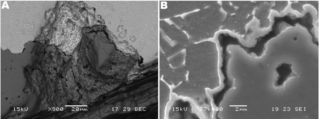
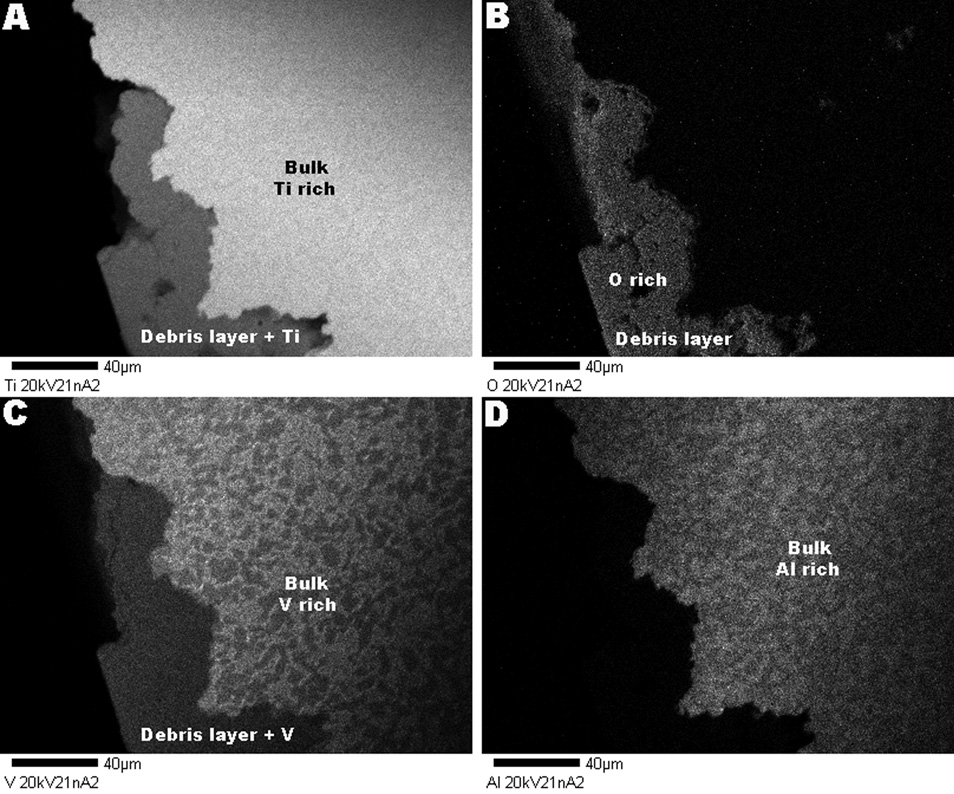
A transverse section of the taper regions shows that cracks were formed in the surface and microstructure of the three different designs. Figure 8 shows transverse sections of the cracking patterns for the Z component (lateral proximal female taper). The section revealed that there is a layer or “debris layer” (dark layer in backscattered mode – BS, see Fig. 8a) following the edge of the sample in regions with interpenetrating cracking and pitting. This layer is present in different regions with cracking and pitting, which resulted in ingress of acidic fluid and debris into the microstructure. This layer of debris is fixed to the surface covering regions with microstructural attack. It can be seen in Fig. 8a that there is a close proximity of the developing pit in the surface alloy and the dark gray material immediately adjacent. These features clearly show the propagating pitting process in the absence of fretting attack. A higher magnification of the areas surrounding the debris layer revealed a region separating this layer from the underlying microstructure, shown in Fig. 8b. A continuous platelet layer lining the surface between the debris zone and the microstructure can be observed (see bright layer in Fig. 8b). This separation region appears to be some form of reaction zone at the surface. This reaction layer looks different than the discontinuous β-phase (β-platelets) in the sense it is much thicker and runs continuously along the debris zone/alloy microstructure interface. In order to determine the chemical composition of the debris layer and assumption of a reaction layer being formed, WDS analysis was performed in the regions illustrated in Fig. 8. Figure 9 illustrates the compositional distribution of the alloy and debris layer in the cross-sectioned taper region of sample Z. The compositional analysis confirmed that the debris layer was formed predominantly by titanium, oxygen and vanadium. Aluminum was not observed within the debris region. The composition patterns illustrated in Fig. 9 were observed for all the regions with the debris deposition. In this figure, the brighter areas show regions rich in the observed element while the darker regions (gray) show lower concentrations. Black regions (Fig. 9d) indicate areas with depletion of the observed element. The analysis did not show a layer of deposits or “debris layer” for the M and S components.
Fig. 8.
SEM micrograph of cracking in the Z component. (a) BS image showing presence of microstructure (top) and debris layer (darker gray, bottom) (900×). (b) Note that the gray (darker gray, bottom) debris layer fills the region of a pit and appears to be a reaction layer converting the alloy to debris with very close proximity with the alloy topography (7,000×).
Fig. 9.
Topographical WDS micrographs. (a) Observation for Ti: Enhanced concentration in the bulk alloy (bright) and presence of the element in the debris layer (gray). (b) Oxygen: presence in the debris area and depletion in the bulk alloy (black). (c) Vanadium: presence of the element in the debris layer and in the bulk (regions of high and low concentration). (d) Aluminum: depletion in the debris layer (black) and presence in the bulk alloy. The debris layer is primarily composed by titanium, vanadium and debris. Aluminum is not reacting to form this layer.
4. Discussion
All the three designs in this study showed pitting, etching, cracking and increased hydrogen concentration in the tapered crevices. Two of the three designs presented multiple evidence that γ-TiH was formed in the modular body tapers. These results demonstrate that hydrogen embrittlement can occur in vivo during the fretting-crevice corrosion process in modular titanium tapers. The corrosion events discussed created the ideal conditions for hydrogen to absorb and diffuse into the surface. Fretting resulted in mechanical abrasion of the oxide film and accelerated local corrosion processes of the metal exposing the surface and microstructure. Crevice corrosion was dramatically increased in the occluded areas where the insufficient exchange of fluids led to depletion of O2 and severe lowering of the pH in the crevices, generating excess of H+ in the anodic reactions occurring in the media. Clear evidence of severe lowering of the pH in the contacting interfaces of the retrieved samples was shown in Fig.1, in which a purple color indicated accelerated oxidation of titanium (presence of Ti3+ ions). Intraoperative pH measures of corroded cemented titanium stems performed by Willert et al. showed low pH of the electrolyte between the stem/cement interfaces, which was measured around 3 or less. As sign of corrosion the authors found violet and black discoloration of the titanium interfaces16. Likewise, Hallan et al.31 performed measurements of pH at the site of corrosion of retrieved titanium hip implants showing highly acidic values (pH = 2.5) at the tip of the stems.
Earlier retrieval studies have demonstrated similar conjoint effects of fretting and crevice corrosion in the mating interfaces of femoral heads and necks. Collier et al.2,3 and Lieberman et al.5 observed corrosion and fretting in mixed-alloy modular prostheses and absence of corrosion in single-alloy modular hip implant connections, drawing the conclusion that there was a galvanic element driving crevice corrosion between Co-Cr and Ti couples. Conversely, Gilbert et al.7 showed evidence of crevice corrosion in both similar metal implants (Co-Cr/Co-Cr couples) and mixed metal cases (Ti-6Al-4V necks/Co-Cr heads) indicating that galvanism is not necessary for crevice attack, but rather that a mechanically assisted corrosion phenomenon is present.
However, hydrogen embrittlement induced by fretting crevice corrosion of modular implants has not been explored in previous retrieval studies, and corrosion at the modular connection (stem/sleeve) of Ti/Ti couples has been only recently addressed by Urban and coworkers9. In this work, Urban hypothesized that accelerated corrosion may occur when titanium alloy stems are inserted without cement and having a modular body design, from which 11 of 14 femoral Ti-6Al-4V prostheses retrieved at revision presented signs of fretting-corrosion at the crevices of the body/sleeve junction.
Multiple observations confirmed the hypothesis of hydrogen embrittlement in vivo during fretting-crevice corrosion of the modular stems. The diffraction studies clearly showed precipitation of hydrides in the M and S components at assigned peaks. The elemental analyses reinforced the diffraction experiments showing that the hydrogen concentration in the taper samples was significantly higher than the concentration measured for the control samples, confirming enhanced hydrogen formation and uptake in the crevices of the M and S modular devices. The hydrogen concentrations in the control samples were relatively high for two of the devices (as shown in Fig. 7) in relation to recommended standards for the bulk concentrations of hydrogen in Ti-6Al-4V alloy. Some of the several possible explanations for the elevated concentration in the control samples are: 1. the bulk hydrogen concentration in the alloys used may have been considerably higher than the recommended ASTM-standards (approximately 0.015wt.%) before the implantation in the body; 2. high temperatures during surface modification of the alloy may have resulted in increased hydrogen levels, considering the higher mobility and diffusion of hydrogen at elevated temperatures; 3. hydrogen levels may have been increased after prolonged immersion in the physiological medium; due to the high mobility of hydrogen in the lattice, the uptake and composition may have become broadly distributed in the alloy. It has also been reported that hydrogen absorption may occur in neutral medium over longer immersion periods24. The SEM study showed morphological evidence of brittle phases in the material (needle-like appearance) and/or HIC (interpenetrating) in the three devices. Figure 3 and Figure 4 showed the morphology of cracking and delamination for the three components in this study. From these figures, it can be seen that the machining lines remained on the surface (top layer) even after fretting-crevice corrosion has taken place and that an intermediate layer of different composition (brighter) is present. These two observations raised the possibility of two particular mechanisms for cracking, HIC (for the M and S components) and subsurface cracking resulting from a dissolution and precipitation process or condensation layer (for the Z component). The features shown in 4b (Z component) may suggest that the pitting process resulted from the detachment of a large metal particle due to subsurface crack growth.
The morphological, diffraction and chemical results suggested that γ-TiH hydride was formed in the taper samples of the M component leading to the delamination effects and needle-like structures observed on the surface. The elemental analysis showed that the hydrogen concentration in the taper samples was significantly higher than the concentration measured for the control sample. The crack propagation in the Z component is strong evidence of hydrogen induced effects. The chemical results showed that the hydrogen concentration in the crevice of this device is significantly higher than in the control region, although not being high enough to precipitate hydride phases (below terminal solubility limit, 0.03 at.%), as confirmed by the diffraction analysis and much lower hydrogen concentrations compared to the other two designs (Fig. 7). γ-TiH is also clearly formed in the taper sample of the S component in the severely corroded region indicating that the cracking mechanism observed was related to hydrogen induced effects. This was also confirmed by the chemical analysis, which showed significantly higher hydrogen concentration in comparison to the control sample. Although Widmanstatten microstructures are known to present superior resistance to crack propagation due to the action of thick β-platelets in the transformed β-phase32, cracking occurred because the accelerated dissolution and fretting led to β-platelets degradation. HIC and brittle phases did not apparently occur with the mild-corroded sample. In this sample the thick β-platelets agglomerated in colonies may have acted as a barrier to hydrogen embrittlement. This explains why the concentration of hydrogen was high for this sample but no hydrogen induced effects and brittle phases were observed. The concentration is as high as the concentration measured for the severely corroded sample, thus the β-platelets in colonies likely absorbed the hydrogen available, increasing the terminal solubility of the alloy.
4.1. Overall mechanisms for cracking
Two possible mechanisms are present in the surface that may have resulted in the observed delamination in layers. The first is a HIC process and the second is a condensation-based process.
1. HIC resulting from the hydrogen embrittlement process
This fact was strengthened by the observation of the crack morphology and by the fact that the machining lines on the top layer remained after fretting-crevice corrosion, therefore some sort of generated stresses (leading to Ti-Ti debonding) or cleavage of brittle phases (intermediate layer) may have induced propagation of cracks of the most superficial layers. The mechanism for HIC may proceed according to the following: 1. the surface gets embrittled by hydrogen penetration; 2. a gray or intermediate layer (in backscattered mode, Fig. 4c) is formed by hydrogen absorption interacting with ions and surface debris and 3. cracking and delamination of most superficial layers results.
2. Condensation layer formed during corrosion and metal dissolution
Besides the HIC model another mechanism may arise when considering the cross-sectional micrographs (presence of “debris layer”), seen in Figs. 8a and 8b, and different chemical appearance of the intermediate layer, seen in Fig. 4c. These micrographs may suggest the following series of events: 1. fretting results in particulate debris of TiO2 and possibly TiH; 2. these insoluble particles condense into a surface layer (gray color, reaction layer) where H2O molecules and H+ ions are still present and actively attacking the metal substrate (shown in white in Fig. 4c) and 3. subsurface cracks arise as avenues for fluid transport into and away from the actively corroding interface. This observation is relevant to explain the interpenetrating crack in the bulk of the Z component. It is possible that both mechanisms have simultaneously contributed for the observed cracking and delamination in the three devices. However, the second mechanism would be more likely to occur with the Z component where interpenetrating cracks (into the bulk) were observed in the absence of hydrogen embrittlement. The first mechanism is possibly responsible for the cracking patterns observed with the S and M components, in which precipitation of hydride phases was confirmed with multiple observations.
4.2. Overall mechanisms for hydrogen generation
During the electrochemical reaction of repassivation (oxide film growth) hydrogen ions are generated as a byproduct at the site of abrasion, according to the reaction series below:
- Passivation and formation of an insoluble oxide or hydroxide involving titanium.
(1) (2) - Cathodic reduction reactions: The oxidation products will react further being consumed by cathodic reduction with oxygen from the medium. Typical cathodic reactions possible to occur from these interactions are:
(3)
These O2 reduction reactions likely occur outside of the taper region (out of the crevice), thereby separating anodic and cathodic reactions.
| (4) |
| (5) |
| (6) |
Hydrogen ions may remain in solution and result in a significant drop in the pH in the vicinity of the mechanically assisted corrosion. This especially occurs if the environment is restricted, limiting the transport of fluids into and out of the crevice, as observed in proximal taper contacting interfaces. Also, surface voltage drops with abrasion increasing cathodic reduction rates. Therefore, at these sites the O2 necessary to consume the products of the oxidation reactions in (2) will be depleted and reaction (3) will not be favored inside the taper, but will be favored outside the crevice. As a result, hydrogen ions will turn the media very acidic and will be free to interact with electrons and form atomic and/or molecular hydrogen species according to reactions (5) and (6). By the reaction products, H atoms will be produced and absorbed into the lattice (forming titanium hydride) or molecular species will be formed on the surface by the recombination of two H atoms. Unless there is a crevice environment associated with fretting or mechanical abrasion of the passive oxide, the conditions for hydrogen absorption will not be present, since reaction (6) will not be favored. Considering these observations, the main source for hydrogen embrittlement in the retrieved samples seems to be more likely related to electrochemical effects. These electrochemical effects associated with the mechanically assisted corrosion observed on the surface of the retrieved samples (fretting, etching-like corrosion) is hypothesized to produce the conditions for hydrogen to diffuse and further interact with the lattice atoms.
It is important to point out that this study involved the worst corrosion cases in the pool of retrievals and therefore, a larger number of implants should be evaluated in order to determine the frequency in which the reported events occur. Clinical parameters such as degree of infection, weight of the patients, age, surgical procedure and degree of activity may or may not assist in determining the rate of corrosion penetration in modular components. However, we were unable to correlate the observed corrosion events in the contacting interfaces with any clinical parameter because a large enough pool of samples was not available for drawing statistical correlations. The clinical reason for retrieval was not thought to be a contributing factor to the damage. In fact, Gilbert et al.7 have discussed in the retrieval study including one hundred forty-eight retrieved modular prostheses of both mixed and similar metal combinations that the statistical analysis revealed no correlation between the extent of corrosion and patient age or sex, reason for removal, metal combinations, whether the device was used for primary or revision surgery or the design.
The configuration of the three different taper designs contributed to the degradation process. The S, M and Z implants were each different in terms of geometry, yet each were susceptible to the development of severe corrosion. The common features in each design include a crevice geometry where fluids can penetrate and high interfacial stresses that can induce fretting of the taper junction. These features enhance crack propagation, fretting and corrosion that can ultimately lead to hydrogen embrittlement.
5. Conclusions
The qualitative analysis of the three Ti-6Al-4V modular stem femoral components has demonstrated that severe corrosion attack of the taper interfaces can take place in vivo. Several features beyond the typical evidence of fretting corrosion, not previously reported, have been demonstrated in this analysis. In particular, severe pitting of the Ti-6Al-4V surface with pits up to 250 µm can occur, and cracking and corrosion of the underlying microstructure may be induced. Both male and female sides of these tapers were susceptible to these effects. Hydrogen embrittlement was observed as an in vivo mechanism of degradation under fretting-crevice corrosion conditions resulting in TiH formation, surface reaction and cracking inside Ti/Ti modular body tapers. The hydrogen generation and absorption are thought to be a consequence of generation of hydrogen ions present in the taper crevice from the fretting corrosion process. The HIC and delamination morphologies in combination with chemical and XRD analysis demonstrated precipitation of hydride phases (γ-TiH) in the surface layer of two of the three modular components in the analysis. The concentration of hydrogen in the samples with precipitation of hydride phases was measured more than ten fold the maximum concentration recommended by the ASTM standards for Ti-6A-4V.
Modularity in the stem/sleeve region of Ti-6Al-4V/Ti-6Al-4V alloy modular body hip implants need to be carefully evaluated in future implant designs, since it was shown to be susceptible to severe degradation and hydrogen induced effects during fretting-crevice corrosion of the contacting interfaces.
Supplementary Material
Acknowledgements
This work was partially supported by grant the NIH AR39310. The authors thank Dr. Robert Urban from Rush University Medical Center (Chicago, IL) for providing financial support and the retrieved samples used in this study, and also Gabriel Armatas from Syracuse University (Syracuse, NY) for his cooperation with the diffraction experiments.
References
- 1.Gilbert JL. ASM International Handbook. 13C. 2006. Mechanically assisted corrosion of metallic biomaterials; pp. 826–836. [Google Scholar]
- 2.Collier JP, Surprenanyt VA, Jensen RE, Mayor MB. Corrosion at the interface of cobalt-alloy heads on titanium alloy stems. Clin Orthop. 1991;271:305–312. [PubMed] [Google Scholar]
- 3.Collier JP, Surprenanyt VA, Jensen RE, Mayor MB, Suprenant HP. Corrosion between the components of modular femoral hip prostheses. J Bone Joint Surg. 1992;74B:511–517. doi: 10.1302/0301-620X.74B4.1624507. [DOI] [PubMed] [Google Scholar]
- 4.Gilbert GL, Jacobs JJ. The mechanical and electrochemical processes associated with taper fretting-crevice corrosion: A review. ASTM STP 1301. 1997:157–176. [Google Scholar]
- 5.Lieberman JR, Rimnac CM, Garvin KL, Klein RW, Salvati EA. An analysis of the head-neck taper interface in retrieved hip prostheses. Clin Orthop Relat Res. 1994;300:162–167. [PubMed] [Google Scholar]
- 6.Griffin CD, Buchanan RA, Lemons JE. In vitro electrochemical corrosion study of coupled surgical implant materials. J Biomed Mater Res. 1983;17:489–500. doi: 10.1002/jbm.820170308. [DOI] [PubMed] [Google Scholar]
- 7.Gilbert JL, Buckley CA, Jacobs JJ. In vivo corrosion of modular hip prosthesis components in mixed and similar metal combinations: The effects of crevice, stress, motion, and alloy coupling. J Biomed Mater Res. 1993;27:1533–1544. doi: 10.1002/jbm.820271210. [DOI] [PubMed] [Google Scholar]
- 8.Goldberg JR, Gilbert JL, Jacobs JJ, Bauer TW, Paprosky W, Leurgans S. A multicenter retrieval study of the taper interfaces of modular hip prostheses. Clin Orthop Relat Res. 2002;401:149–161. doi: 10.1097/00003086-200208000-00018. [DOI] [PubMed] [Google Scholar]
- 9.Urban RM, Gilbert JL, Jacobs JJ. ASTM International. Vol. 2. 2005. Corrosion of modular titanium alloy stems in cementless hip replacement; pp. 1–10. [Google Scholar]
- 10.Barrack RL. Stem modularity is unnecessary in revision total hip arthroplasty. J Arthroplasty. 2003;18:98–100. doi: 10.1054/arth.2003.50075. [DOI] [PubMed] [Google Scholar]
- 11.Lombardi AV, Mallory TH, Fada RA, Adams JB. Stem modularity: rarely necessary in primary total hip arthroplasty. Orthopedics. 2002;12:1385–1387. doi: 10.3928/0147-7447-20021201-17. [DOI] [PubMed] [Google Scholar]
- 12.Cameron HU. The long-term success of modular proximal fixation stems in revision total hip arthroplasty. J Arthroplasty. 2002;17:138–141. doi: 10.1054/arth.2002.32462. [DOI] [PubMed] [Google Scholar]
- 13.Brown SA, Hughes PJ, Merritt K. In vitro studies of fretting corrosion of orthopaedic materials. J Orthop Res. 1988;6:572–579. doi: 10.1002/jor.1100060415. [DOI] [PubMed] [Google Scholar]
- 14.Geringer J, Forest B, Combrade P. Fretting corrosion of materials used as orthopedic implants. Wear. 2005;259:943–951. [Google Scholar]
- 15.Griess JC., Jr Crevice corrosion of titanium aqueous solutions. Corrosion. 1968;24:96–109. [Google Scholar]
- 16.Willert HG, Broback LG, Buchhorn GH, Jensen PH, Koster G, Lang I, Ochsner PO, Schenk R. Crevice corrosion of cemented titanium alloy stems in total hip replacements. Clin Orthop Rel Res. 1996;333:51–75. [PubMed] [Google Scholar]
- 17.Levine DL, Staehle RW. Crevice corrosion in orthopaedic implants metals. J Biomed Mater Res. 1977;11:553–561. doi: 10.1002/jbm.820110410. [DOI] [PubMed] [Google Scholar]
- 18.Troiano RT. Transactions of the ASM. Vol. 52. 1960. The hole of hydrogen and other interstitials in the mechanical behavior of metals; pp. 54–80. [Google Scholar]
- 19.Oriani RA, Josephic PH. Equilibrium aspects of hydrogen induced cracking in steels. Acta Metall. 1974;22:1065–1074. [Google Scholar]
- 20.Oriani RA. The physical and metallurgical aspects of hydrogen in metals. Trans Fusion Technol. 1994;26(ICCF4):235–266. [Google Scholar]
- 21.Jones DA. Principles and Prevention of Corrosion. New York: Macmillan; 1992. [Google Scholar]
- 22.Gutelmacher E, Eliezer D. Hydrogen cracking in titanium-based alloys. J Alloys and Compounds. 2005;404:621–625. [Google Scholar]
- 23.Yokoyama K, Ogawa T, Asaoka K, Sakai J. Hydrogen absorption of titanium in acidic fluoride solutions. Mater Sci Eng. 2004;A384:19–25. [Google Scholar]
- 24.Yokoyama K, Ogawa T, Asaoka K, Sakai J. Hydrogen absorption of titanium and nickel-titanium alloys during long-term immersion in neutral fluoride solution. J Biomed Mater Res B. 2005;78B:204–210. doi: 10.1002/jbm.b.30485. [DOI] [PubMed] [Google Scholar]
- 25.Urban RM, Gilbert JL, Jacobs JJ. Corrosion and corrosion products generated by three designs of cementless hip stems with a Ti-alloy/Ti-alloy modular body junction. Trans Orthop Res Soc Annual Meeting; San Diego: Feb, 2007. [Google Scholar]
- 26.Goldberg JR, Gilbert JL. In vitro corrosion testing of modular hip tapers. J Biomed Mater Res B. 2003;64B:78–93. doi: 10.1002/jbm.b.10526. [DOI] [PubMed] [Google Scholar]
- 27.Chandrasekaran V, Sauer WL, Taylor AM, Hoeppner DW. Evaluation of the fretting corrosion behavior of the proximal pad taper of a modular hip design. Wear. 1999;23:54–64. [Google Scholar]
- 28.Burstein GT, Liu C, Souto RM. The effect of temperature on the nucleation of corrosion pits on titanium in Ringer’s physiological solution. Biomaterials. 2005;26:245–256. doi: 10.1016/j.biomaterials.2004.02.023. [DOI] [PubMed] [Google Scholar]
- 29.Barril S, Mischler S, Landolt D. Electrochemical effects on the fretting corrosion behavior of Ti6Al4V in 0.9% sodium chloride solution. Wear. 2005;259:282–291. [Google Scholar]
- 30.Wang T, Eichhorn F, Grambole D, Groetzchel R, Herrmann F, Kreissig U, Moeller W. A new Ti/H phase transformation in the H2 titanium alloy studied by x-ray diffraction, nuclear reaction analysis, elastic recoil detection analysis and scanning electron microscopy. J Phys: Condens Matter. 2002;14:11605–11614. [Google Scholar]
- 31.Hallan P, Haddad F, Cobb J. Pain in well-fixed, aseptic titanium hip replacement. J Bone Joint Surg. 2004;86B:27–30. [PubMed] [Google Scholar]
- 32.Hack JE, Leverant GR. The influence of microstructure on the susceptibility of titanium alloys to internal hydrogen embrittlement. Metall Trans A. 1982;13A:1729–1738. [Google Scholar]
Associated Data
This section collects any data citations, data availability statements, or supplementary materials included in this article.


