

Abstract
The paper gives an analytical approximation to the viscous damping coefficient due to the motion of a gas between a pair of closely spaced fluctuating plates in which one of the plates contains a regular system of circular holes. These types of structures are important parts of many microelectromechanical devices realized in MEMS technology as microphones, microaccelerometers, resonators, etc.
The pressure satisfies a Reynolds’ type equation with coefficients accounting for all the important effects: compressibility of the gas, inertia and possibly slip of the gas on the plates. An analytical expression for the optimum number of circular holes which assure a minimum value of the total damping coefficient is given. This value realizes an equilibrium between the squeeze-film damping and the viscous resistance of the holes.
The paper also provides analytical design formulas to be used in the case of regular circular perforated plates.
Keywords: MEMS, Perforated structures, Viscous damping, Optimum number of holes, Minimum total damping
1. Introduction
The study of the motion of a thin fluid layer squeezing between a vibrating plate (or proof mass) and a backplate electrode (or between the two vibrating plates in other applications), referred as a planar microstructure, is important in many microelectromechanical devices such as microphones [1], microaccelerometers [2], micromechanical switches [3], various resonators [4], and tunable microoptical interferometers [5]. The motion of the thin film of air in a planar microstructure generates a squeeze-film damping that can adversely affect the dynamic response of the system [6].
The excessive gas damping problem is often solved by “drilling” perforations in one of the plates. In fact, the use of perforated plates in surface-micromachined planar microstructures has a double role: it reduces the squeeze-film damping effect and enhances the etching of underlying sacrificial layers in the microfabrication process. Thus, the perforations are compatible with the thin film processing and add very little to the manufacturing cost.
While the squeeze-film damping is reduced by incorporating holes in the backplate, the motion of the air within the backplate holes gives a new viscous resistance which adds to the squeeze-film damping. Previous work devoted to the viscous damping in planar microstructures has considered, in many cases, only the squeeze-film damping. Thus, Škvor [7] using a simplified hydraulic model succeeded in obtaining an analytical formula for evaluating the squeeze-film damping in some acoustical devices. Škvor’s result is applicable to incompressible fluids and neglects any added damping due to the flow through the holes. The viscous hole resistance effect was considered by Rossi [8] in some acoustical applications. Recently, Veijola and Mattila [9] and Bao et al. [10] developed damping models incorporating the holes resistance in the linearized Reynolds equation.
These two viscous effects, namely the squeeze-film damping due to the horizontal motion of the air between the plates and the resistance due to the vertical motion of air through the holes are not independent. In order to decrease the squeeze-film damping we have to “drill” more and more holes but each new hole adds its resistance to the total damping. Thus, we expect the existence of an optimum number of perforations that minimizes the viscous damping and corresponds to an equilibrium between the two components of the viscous damping. For the case of incompressible fluids such an analysis was performed in [11]. In the present study, we extend some of these results to account for the effects of compressibility, inertia, and the gas slip on surfaces. A primary aim of this paper is to present practical formulae that are more widely applicable than previous results and, in electrically driven or sensed devices, have the minimal gas damping for an assumed capacitance.
The analysis performed in this work is quite general being applicable to a very large spectrum of frequencies and to various fluids. The departing point is the Navier–Stokes system. As the domain of the fluid motion is very thin, an asymptotic analysis of this partial differential equation system was considered. In order to include the inertia effects, important at large frequencies, the terms containing the time derivatives of velocity were maintained in the system. Also, are considered the first-order slip velocity conditions on the plates, important in the case of slightly rarefied gases [12]. The final equation for the pressure has the same form as Reynolds equation but with different coefficients accounting for all the described effects.
The case of a planar microstructure containing a regular web of circular holes is considered as an application. The cell corresponding to a certain hole (by cell we mean the influence domain of the hole) is a regular polygon. The normal derivative of the pressure along the boundary polygonal line is zero while the pressure has a constant value along the holes’ rim. In solving the resulting boundary value problem for a certain cell the external curve will be approximated by an equivalent circle enclosing the same area. The mixed Dirichlet–Neumann problem for an annulus in the case of Reynolds’ equation can be solved explicitly. Hence, the squeeze-film damping can be expressed analytically. For the case of small frequencies and low compressibility, the resulting formula coincides with that given in [11]. Also, the holes resistance can be determined explicitly by solving a similar Helmholtz-type equation for the Poiseuille flow in a circular pipe.
The total damping coefficient, expressed in terms of number of holes on an unit of area, has a minimum value for a certain number of holes (optimum number of holes on a unit area). Afterwards, designing formulas are given which determine the geometry of the structure such that the resulting micromechanical structure has the smallest damping for an assigned open area.
In order to give an estimation of the error involved by changing the external boundary curve of the cell into a circle, a model problem for an incompressible fluid was considered. In this case, the mixed problem for the exact domain was solved by a numerical boundary element technique. The comparison of the two solutions (one approximate analytical and the other one numerical) shows that for the case where the open area ratio AR is smaller than 0.4 the precision of the analytical formulas is very good, while for AR > 0.5 the precision is decreasing.
As a byproduct of this calculation a correction term for the Škvor’s analytical formula for the cases 0.4 < AR < 0.75 was obtained.
For a finite plate the real damping force depends on the plates’ boundary which is decreasing the pressure. Hence, the damping coefficient resulting by the present analysis is conservative; for a better approximation of this coefficient, corresponding to a particular structure, a more elaborate analysis [9,10]working in the specified case has to be performed.
2. Formulation of the problem
In order to study the viscous damping on a planar microstructure we model the air in the gap between the two parallel plates as a compressible Newtonian gas. We refer the motion of the fluid to a Cartesian system of coordinates whose origin O is halfway between the plates average position the xOy-plane parallel to the two plane surfaces (Fig. 1).
Figure 1.
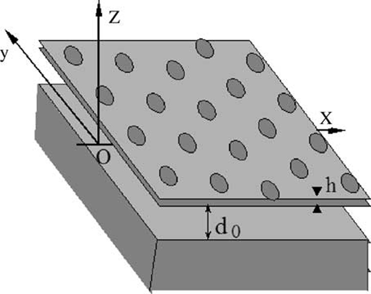
A perforated planar microstructure.
2.1. Equations of the fluid motion (horizontal flow)
The isothermal motion of the gas is described by the Navier–Stokes system: the continuity equation,
| (1) |
and the momentum equations,
| (2) |
where ρ is the density, c the isothermal speed of sound, p and v are perturbations of the pressure and velocity, μ and λ are the shear and bulk viscosities and g the gravity acceleration.
In the case of simple harmonic oscillations (of frequency ω/2π) we have
Eq. (1) and Eq. (2) then become
| (3) |
| (4) |
It is helpful to recast these equations using dimensionless variables. As the domain in our case is the narrow air gap between the two plates, we will use different scales on the x, y-directions and the z-direction.
d0 being the distance between plates at equilibrium, L0 is a characteristic length connected to the planar domain and ε = d0/L0 is a small parameter. The other reference variables have characteristic values. In the following, we drop the primes and remember that we are now working in dimensionless variables. To the lower order in ε we obtain the equations
| (5) |
| (6) |
| (7) |
| (8) |
where we have denoted
Most approaches of the thin-film problems are neglecting completely the inertial terms. This is justified when the flow is steady, or slowly oscillating. However, when the oscillation frequency increases the inertia of the gas has a significant influence on the velocity profile. In Eq. (5)–Eq. (8) the terms containing the parameters K and K1 include the dependence of the mechanical quantities upon frequency.
2.2. The boundary conditions for the gas velocity and pressure
For including the case of slightly rarefied compressible gas, we consider first-order slip velocity conditions at solid boundaries instead of the usual nonslip conditions [12]:
| (9) |
where λ′ is the mean free path of the gas molecules. Also, in the direction normal to the plates we have
| (10) |
By w we denote the Oz-component of the velocity of the mobile surface, assumed a known quantity. (The classical nonslip condition can still be obtained for λ′ = 0.)
At the rim of the holes the pressure is assumed to be equal to the atmospheric pressure. This gives the condition
| (11) |
on the rim ∂DD of the holes. The pressure gradient is zero in a direction that is normal to any line of symmetry of the planar microstructure. On all symmetry lines (denoted by ∂DN), we can then write a new boundary condition as
| (12) |
We suppose that the holes (of circular form of r1—radius) are located at the vertices of a regular system of equilateral triangles of l—side length (Fig. 2). We will take advantage of the repetitive pattern of the perforated plate and define a “cell” as the space occupied by a hole and its surrounding web space (the plane region where the hole is collecting the flow). The basic domain D is defined as the plane region obtained from a cell excluding the hole (Fig. 3). The external boundary of the basic domain is a regular hexagon and the inner boundary is the rim of the hole.
Figure 2.

The regular web of holes on the upper plate.
Figure 3.

The influence domain (the cell) of the central hole and its circular approximation.
3. The Reynolds equation for the gas squeezing film
By integrating Eq. (5) and Eq. (6) and using the boundary conditions Eq. (9) we obtain expressions for the horizontal components of velocity
| (13) |
| (14) |
where Eq. (8) then becomes
Integration of this equation with respect to z yields a formula for the vertical component of velocity and also an equation for the pressure
| (15) |
Here we have used the notations
| (16) |
Eq. (15) is the Reynolds’ equation for solving the squeezing film problem in the case of a compressible gas accounting also for the influence of inertia and gas slip on the plates. In the case we have c0≫ 1 (the low compressibility case) Eq. (15) becomes Poisson’s equation:
| (17) |
Finally, the physical pressure on the membrane can be expressed by means of the relation
| (18) |
where wphys = εV0we−iωt and the function p̂ satisfies the canonical boundary value problem
| (19) |
The canonical domain D′ results from the basic domain D by means of the similarity transformation given by using dimensionless variables.
In the case where the gas is sticking to thewall (λ′ = 0) and for small to moderate values ofK-numbers (slowly oscillating flow), a series expansion enables Eq. (16) to be approximated as
A simple dimensional analysis reveals that for the case of the air and of frequencies between 100 Hz and 50 kHz the value M = 1 is a good approximation.
We will define also the pressure coef.cient Cp of the domain D′ as
| (20) |
Hence, the resulting force due to the squeeze-film damping on a cell of the mobile plate is
| (21) |
The damping coefficient of a particular structure is obtained by summing the force corresponding to all the cells of the structure and dividing the result by velocity wphys.
At small pressures, when the molecular mean free path λ′ is not negligible compared with the gap width, the Reynolds equation (15) is still valid if the viscosity coefficient μ is substituted by
| (22) |
Kn = λ′/d being the Knudsen number. For a summary of different functions f (Kn) used in literature to model the gas flow in a narrow gap and a more elaborate discussion on this topic the reader is directed to the paper [13].
4. The annular approximation of the basic region: squeeze-film damping
We consider an approximation of the outer hexagonal boundary of the basic domain by an equivalent circle having the same area (Fig. 3). In this case the domain D is an annulus of r1 < r2 radii. The radius of the outer circle r2 is connected with the distance l between the holes by the relationship
resulting by the equality of areas. This approximation works well only in the case of small inner radius r1 as compared with the linear dimension of the cell. In fact, the comparison of the analytical results obtained by this simplified model with the data provided by the numerical solution, given in the last section, will show the limits of the used approximation. We take as a reference length L0 = r2 and denote r0 = r1/r2. In this case the basic equation (17) becomes in polar coordinates
| (23) |
The boundary conditions for the function p(r) are
| (24) |
4.1. Squeezing viscous damping: the influence of compressibility and inertia
The solution of Eq. (23) satisfying the conditions (24) can be written as
where J0, J1, Y0, Y1 are the Bessel functions of the first and second kind.
We have also
where
A power series expansion yields
where
Therefore,
| (25) |
The positive coefficients c0(r0), c1(r0) are plotted in Fig. 4. The first term in formula (25) corresponds to the incompressible case and the next term gives the influence of compressibility and inertia. Finally, the total force on the domain D due to squeeze-film damping can be written as
| (26) |
From Fig. 4 it can be seen that the compressibility is important only for the case of very small r0 = r1/r2 ratio. For an incompressible fluid (α = 0), the resulting expression reduces to
| (27) |
given in [11]. In the case of small or moderate frequencies the relationship (27) coincides with Škvor’s formula [7].
Figure 4.

The functions c0(AR) and c1(AR).
5. Viscous resistance due to the microstructure holes (vertical flow)
In this section, we extend the previous results to account for the supplementary pressure due to the resistance of the flow through holes. As in the above formulation, the effects of compressibility and the inertia effects will be accounted for. In order to determine the “holes resistance” we assume a pressure p1 along the upper edge of a perforation and model a plate hole as a pipe of 2r1 diameter and of length h equal to the plate thickness. In this case the only nonvanishing component of velocity in the hole is vz (Poiseuille flow) [14] and we can write the equation
ν = μ/ρ being the dynamic viscosity. In polar coordinates there results
an equation similar to (23). Its solution, finite in the domain r < r1 and vanishing on the pipe wall r = r1 is
where β2 = iω/ν. The total volume rate of flow results by integration in the form
In the case βr1 < 1 we can write
In the incompressible case the pressure p1 at the rim of the hole can be obtained by balancing this volume rate of flow with the volume rate of flow Q = 𝒜w entering (or leaving) the space between the microstructure plates (by𝒜we denoted the cell’s area). Hence there results
| (28) |
This rim pressure gives a supplementary force on the cell, which may be written as
| (29) |
The first term in Eq. (28), which is in phase with w, causes the pressure in Eq. (29) to correspond to static Poiseuille flow and has been given by Rossi in [8]. The second term in Eq. (28), accounts for the effect of the oscillation frequency.
The formula (29) shows that the resistance due to the flow through the holes is important in the case of small diameter holes (i.e. small r1) and thick plates (i.e. large h). It is quite common in devices such as microaccelerometers that the proof mass thickness is as much as 10 times larger than the gap dimension so that the hole resistance is an important component of the viscous damping.
The difficult fluid dynamic problem of the motion of the gas in the perforated micromechanical system has been decomposed in two simpler flows: a horizontal (squeezing film) flow and a vertical (Poiseuille) flow. In the case where the thickness of the plate h and the radius r1 are of comparable dimensions a correction has to be made for the effect of the holes’ end. Sharipov and Seleznev [15] have shown that this effect can be included in formula (29) by replacing the holes’ length h with
On the other side, if the holes are very thin (Knudsen number is large) the flow resistance can be determined again by the same formula if the effective viscosity
stands for viscosity. Values of the function Gtb can also be found in [15].
6. Optimal number of circular holes and designing relationships
By adding the two terms modelling the viscous damping: the squeezing mechanical damping given in Eq. (26) or (27) and the plate holes resistance in Eq. (29) we obtain the total force on a microstructure cell as
| (30) |
where different viscosities μ′,μ″ have been introduced accounting for possible different effective viscosities on the horizontal and/or vertical flow and, again, r0 = r1/r2. We introduce as new variables N the number of holes on a unit area u2 and AR the area ratio (area fraction of holes)
For a given plate thickness h, air gap thickness d0, and area ratio AR, it is often desirable to determine the number of holes, N, and their dimensions in order to minimize the damping pressure. The total damping coefficient ℬ on a unit area of the diaphragm is
The modulus of ℬ can be written as
where . For N = Nopt
| (31) |
the modulus of the damping coefficient attains its minimum value
| (32) |
In the case of an incompressible gas and moderate frequencies these formulas yield
| (33) |
| (34) |
Denoting by l the distance (in u—units) between the centers of two neighboring circular holes (see Fig. 3), we have the designing relationships
| (35) |
For example, in the case of a microstructure with AR = 0.2, d0 = 0.005 mm, h = 0.004mm and neglecting the air compressibility (α = 0) there results
Remark 1
It is possible that in some cases the value r1opt will be too small to be realized technologically. In this case r1opt = r1min (r1min being the radius of the minimum circle which can be “drilled”) and the formulas (100) will be used for determining the designing variables r2opt, Nopt and lopt. Correspondingly, the squeeze-film damping will be the dominating part in the total viscous damping.
7. Optimal number of holes: a numerical estimation of the accuracy
The results presented above are based on a circular approximation of the real polygonal external boundary of the cell (Fig. 3). To determine the error involved in this approximation a model problem for the case of an incompressible gas was simulated numerically by using a boundary element method. Thus, the mixed boundary value problem for Eq. (17) and the real basic domain D (delimited by the inner circle of radius r1 and the external polygonal line) was integrated numerically by using a complex variable boundary element algorithm [16] and yielding finally the pressure coefficient Cp of the canonical domain. Now the force on a cell due to squeeze-film damping can be written as
and, also, the viscous resistance of the hole (29), gives the force
The geometrical parameters AR and N (the number of holes on a unit of area u2) are now
An analysis similar to that in the previous section gives the optimal number of holes
and the minimum value of the principal part of the damping coefficient
| (36) |
In Fig. 5 we present a comparison of the optimum number of holes computed by using the analytical formula (33) (small circles) and the value resulting from numerical integration (asterisks) in this section. It is evident that for AR < 0.4 the two values are very close.
Figure 5.

A comparison of the optimal number of holes given by analytical (Škvor’s) formula (circles), numerical simulation (asterisks) and modified Škvors’ formula (continuous line).
By comparing the formulas (34) and (36) there results
| (37) |
In Fig. 6 we plot the value of the coefficient Cp given by formula (37) (small circles) and the value obtained by numerical computation (asterisks). By using the obtained numerical values, we have determined also a corrected value (the improved Škvor’s formula) to the coefficient in the form
| (38) |
valid for 0.4 < AR < 0.75, which is also plotted in Fig. 6 as a continuous line. The optimum number of holes resulting by using the function in formula (33) is also plotted in Fig. 5 as a continuous line. It is evident that the analytical designing formulas presented in Section 6 can be used for all the area ratio values of practical interest if we consider the coefficient instead of in the case the area ratio AR is larger than 0.4.
Figure 6.

A comparison of the minimum total damping coefficient given by analytical formula (circles) by numerical simulation (asterisks) and modified analytical formula (continuous line).
8. Conclusions
The paper provides damping coefficients for the case of regularly perforated plates valid for all frequencies and including the effect of compressibility, inertia, and gas slip on solid surfaces. For a regular web of circular holes, the paper gives designing analytical formulas for determining the optimal number of holes (on a unit of area) which give the smallest total damping coefficient for an assumed open area.
The analysis in the last section (based on an incompressible model) has shown that the obtained approximate analytical formulas given in Section 6 can be used as long as AR < 0.4. For the incompressible fluid and 0.4 < AR < 0.75 a correction term to Škvors’ formula is obtained.
Acknowledgement
This work has been supported through NIH grant R01 DC05762-01A1 and DARPA grant DAAD17-00-C-0149 to R.N.M.
Biographies
Dorel Homentcovschi received the M.Sc. and Ph.D. degrees from University of Bucharest, Romania, in 1965 and 1970, respectively. In 1970, he joined the Polytechnic Institute of Bucharest where he is now Professor in the Department of Mathematics. Beginning in 1995 he is also a First Degree Researcher at the Institute of Mathematical Statistics and Applied Mathematics of the Romanian Academy. Between 1995–2001 he was director of the Institute of Applied Mathematics of the Romanian Academy. In the period 2001–2004 he is with the Department of Mechanical Engineering at the State University of New York at Binghamton as a Research Professor. He has written many scientific papers and reports and co-authored several books. His research interests are in the areas of boundary-value problems, fluid mechanics, acoustics, elasticity, microelectronics, and MEMS.
Dr. Homentcovschi was awarded the Gheorghe Lazar Prize for a paper on aerodynamics in 1974, and Traian Vuia Prize in 1978, for work concerning resistive structures in microelectronics, both from the Romanian Academy.
R.N. Miles received a BSEE from the University of California at Berkeley in 1976, and his MSE and Ph.D. in mechanical engineering from the University of Washington. Beginning in 1977 he worked on structural acoustics and noise control at Boeing for eight years. He was an assistant research engineer and lecturer in the Department of Mechanical Engineering at UC Berkeley and has been with the Department of Mechanical Engineering at the State University of NewYork at Binghamton since 1989 where he is now Professor. His primary research is on the development of biologically-inspired acoustic sensors.
References
- 1.Bergquist J. Finite-element modelling and characterization of a silicon condenser microphone with a highly perforated backplate, Sens. Actuators A. 1993;39:191–200. [Google Scholar]
- 2.Novack MJ. 1992. Design and fabrication of thin film micromachined accelerometer, M.S. Thesis, Massachusetts Institute of Technology . [Google Scholar]
- 3.Pacheco S, Nguyen CT-C, Katehi LPB. Micromechanical electro-static K-band switches; Proceedings of the IEEE on MTT-S International Microwave Symposium; June 7–12, 1998; Baltimore, MD. pp. 1569–1572. [Google Scholar]
- 4.Mattila T, Hākkinen P, Jaakola O, Kiihamāki J, Kyynārāinen J, Oja A, Seppā H, Seppālā P, Sillanpāā T. Proceedings of the 14th European Conference on Solid-state Transducers. EUROSENSORS XIV; Copenhagen: 2000. Air damping in resonant micromechanical capacitive sensors; pp. 221–224. [Google Scholar]
- 5.Wu MS, Vail EC, Li GS, Yuen W, Chang-Hasnain CJ. Widely and continuously tunable micromachined resonant cavity detector with wavelength tracking. IEEE Photon. Technol. Lett. 1996;8:98–100. [Google Scholar]
- 6.Bao M-H. Micro Mechanical Transducers. Amsterdam: Elsevier; 2000. [Google Scholar]
- 7.Šcvor Z. On acoustical resistance due to viscous losses in the air gap of electrostatic transducers. Acoustica. 1967;19:295–297. [Google Scholar]
- 8.Rossi M. Acoustics and Electroacoustics. Norwood: Artech House; 1988. [Google Scholar]
- 9.Veijola T, Mattila T. Compact squeezed-film damping model for perforated surface. Proceedings of the Transducers’01; München; June 10–14, 2001; Germany. pp. 1506–1509. [Google Scholar]
- 10.Bao M, Yang H, Sun Y, French PJ. Modified Reynolds’ equation and analytical analysis of squeeze-film air damping of perforated structures. J. Micromech. Microeng. 2003;13:795–800. [Google Scholar]
- 11.Homentcovschi D, Miles RN. Modelling of viscous damping of perforated planar micromechanical structures, applications in acoustics. J. Acoust. Soc. Am. 2004;116(5):2939–2947. doi: 10.1121/1.1798331. [DOI] [PubMed] [Google Scholar]
- 12.Veijola T. Acoustic impedance elements modeling gas flow in micro channels; Proceedings of the MSM 2001; March 19–21, 2001; Hilton Head, SC. pp. 96–99. [Google Scholar]
- 13.Veijola T, Kuisma H, Lahdenperä J, Ryhänen T. Equivalent-circuit model of the squeezed gas film in a silicon accelerometer. Sens. Actuators A. 1995;48:239–248. [Google Scholar]
- 14.White FM. Viscous Fluid Flow. McGraw-Hill: 1992. [Google Scholar]
- 15.Shapirov MH, Seleznev V. Data on internal rarefied gas flows. J. Phys. Chem. Ref. Data. 1997;27:657–706. [Google Scholar]
- 16.Homentcovschi D, Cui W, Miles RN. Modelling of viscous squeeze-film damping of perforated micromechanical structures by complex variable boundary element method. submitted for publication. [Google Scholar]