Abstract
Lizard skulls vary greatly in shape and construction, and radical changes in skull form during evolution have made this an intriguing subject of research. The mechanics of feeding have surely been affected by this change in skull form, but whether this is the driving force behind the change is the underlying question that we are aiming to address in a programme of research. Here we have implemented a combined finite element analysis (FEA) and multibody dynamics analysis (MDA) to assess skull biomechanics during biting. A skull of Uromastyx hardwickii was assessed in the present study, where loading data (such as muscle force, bite force and joint reaction) for a biting cycle were obtained from an MDA and applied to load a finite element model. Fifty load steps corresponding to bilateral biting towards the front, middle and back of the dentition were implemented. Our results show the importance of performing MDA as a preliminary step to FEA, and provide an insight into the variation of stress during biting. Our findings show that higher stress occurs in regions where cranial sutures are located in functioning skulls, and as such support the hypothesis that sutures may play a pivotal role in relieving stress and producing a more uniform pattern of stress distribution across the skull. Additionally, we demonstrate how varying bite point affects stress distributions and relate stress distributions to the evolution of metakinesis in the amniote skull.
Keywords: biting, finite element analysis, multibody dynamics analysis, skull
Introduction
This study addresses the mechanical function of the skull of the lizard Uromastyx hardwickii (Squamata, Agamidae) using a combined finite element analysis (FEA) and multibody dynamics analysis (MDA) approach. Uromastyx is generally considered to be one of the two basal agamid genera (the other being Leiolepis) and is interesting as (1) being primarily herbivorous, (2) having a specialized arrangement of the pterygoideus muscle whereby an additional external slip attaches to the outside of the skull, and (3) in having a skull that is said to be essentially akinetic (lacking obvious intracranial movements) but hyperstreptostylic (Throckmorton, 1976). Uromastyx is a common ground-living lizard in India, Africa and the Middle East and has therefore been quite well described in the literature (e.g. Saksena, 1942; El-Toubi, 1945; George, 1955; Islam, 1955; Throckmorton, 1976). With regard to mechanical function we are concerned to investigate the relationship between sutures and stress distribution, the extent to which there is potential for metakinesis, and the effects of varying bite point on stresses.
The application of FEA and MDA has increased rapidly in the area of functional morphology, as these technologies have the potential to advance our understanding of the driving forces that shape bone, as well as more complex and specific structures such as the skull (e.g. McHenry et al. 2007; Curtis et al. 2008). The advantages of using these mechanical engineering tools is that forces acting upon the skull can be estimated and then applied to a model of it to estimate patterns of strain and stress across the skull. In conjunction with knowledge of evolutionary paths, this information can be used to develop hypotheses regarding the genetic and epigenetic factors that shape the skeleton. Both MDA and FEA warrant a brief overview.
MDA involves two or more rigid bodies whose motions can be independent of each other, or whose motions are constrained by joints or specified contact surfaces and springs. As the term rigid body implies, no deformation of the geometries occurs, and as such, deformation does not affect gross body motion. This area of dynamics can be divided into two disciplines: (1) a kinetic analysis, which is the study of motion produced under the action of forces, and (2) a kinematic analysis, which is the study of motion regardless of the masses or forces. For example, a kinetic simulation is applied when assessing jaw motion that is driven by the masticatory muscles, and a kinematic simulation is applicable when a rotation is defined to a joint and motion is produced without concern for mass and muscle forces (e.g. Geradin & Cardona, 2001; Hannam, 2003). FEA works by dividing the geometry of the problem under investigation (e.g. a skull) into a finite number of sub-regions, called elements, which are connected together at their corners (and sometimes along their mid-sides). These points of connection are called nodes. For stress analysis, a variation in displacement (e.g. linear or quadratic) is then assumed through each element, and equations describing the behaviour of each element are derived in terms of the (initially unknown) nodal displacements. These element equations are then combined to give a set of system equations which describes the behaviour of the whole problem. After modifying the equations to account for the loading and constraints applied to the problem, these system equations are solved. The output is a list of all the nodal displacements. The element strains can then be calculated from the displacements, and the stresses from the strains. More detailed descriptions of FEA principles and its applications to craniofacial mechanics are available (e.g. Fagan, 1992; Richmond et al. 2005; Rayfield, 2007).
MDA, predominately an engineering tool, was brought to the area of biomechanics to study human movement, and more recently it is being used by those interested in functional morphology (e.g. Langenbach et al. 2002; Sellers & Crompton, 2004; de Zee et al. 2007; Curtis et al. 2008; Moazen et al. 2008). MDA can be used to estimate the loading conditions that act, for example, on the skull during biting and which, if modelled accurately, will provide more precise data for FEA. Whereas MDA is a relatively under-utilized tool in this area, FEA is widely applied, with some authors adopting inductive methods (Preuschoft & Witzel, 2002, 2005) and some deductive methods (e.g. Rayfield et al. 2001; Dumont et al. 2005; Ross et al. 2005). Recent FEA studies have become increasingly complex, with approximations in material properties of bone (e.g. Strait et al. 2005; Wang & Dechaw, 2006) and the representation of muscle loading (e.g. Grosse et al. 2007; Wroe et al. 2007) being addressed more thoroughly. However, so far there are few combined MDA and FEA studies in the literature (e.g. Koolstra & van Eijden, 2005, 2006; Curtis et al. 2008).
The aim of this present phase of our work is to evaluate the potential of an MDA approach to the loading of skulls using a finite element model of Uromastyx. In this paper, the resulting MDA load data are used to explore the variation of stress across the skull to consider the possible role of sutures, the potential for metakinesis and the effects of varying bite point. During each simulation, gape angle, muscle force, bite force and joint force all vary with time, with the MDA solution outputting the load data at discrete time steps. These load steps are then transferred to the FE analysis, where the variation of stress and strain over time can be examined. In this study we also compared the results of FEA models that used MDA load data with models using loading methods more widely described in the literature.
Materials and methods
Multibody dynamics analysis
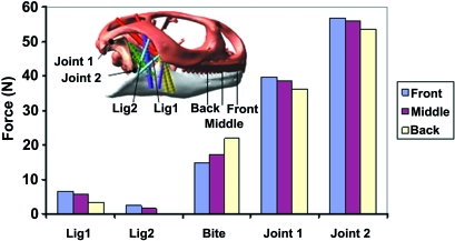
The development of a multibody dynamics model and its subsequent simulations has been discussed in detail previously (Moazen et al. 2008). In brief, three-dimensional models of the cranium, mandible and quadrates of a Uromastyx hardwickii skull were constructed from microCT data and then imported into MSC ADAMS motion simulation software (Santa Ana, CA, USA) in preparation for a multibody dynamics analysis. Mass properties were assigned to the moving parts (jaw and quadrates) and soft tissue structures (i.e. muscles and ligaments) applied. The ligaments were modelled as tension-only springs (i.e. no compressive resistance) and the jaw-closing muscles [named as adductor mandibulae externus superficialis anterior (MAMESA), adductor mandibulae externus superficialis posterior (MAMESP), adductor mandibulae externus medialis (MAMEM), adductor mandibulae externus profundus (MAMEP), pterygoideus externus (MPTE), pterygoideus medialis (MPTM) and the pseudotemporalis superficialis (MPST)] were defined with Hill-type muscle properties (Hill, 1938) as described by van Ruijven & Weijs (1990). A kinematic analysis was performed to open the jaw, and then muscle forces, which varied with gape, were applied to close the jaw during a forward dynamic biting simulation. Ligament, bite and joint forces were calculated, as a food particle with viscoelastic material properties (i.e. stiffness of 50 N mm−1 and damping ratio of 9 Ns mm−1) was modelled in the mouth aligned perpendicular to the teeth. The food particle was placed at three positions, moving from the front of the mouth (incisiform tooth) to the back of the mouth (posterior teeth) (Fig. 2).
Fig. 2.
Variation in the bite force, joint force and ligament force as a result of moving the bite point from the front of the mouth to the back. All values are taken at a gape of 10° and reported for the right-hand side of the model.
Finite element analysis
The three-dimensional model of the cranium developed for the MDA was transformed into a meshed solid geometry using AMIRA image segmentation software (Mercury Computer Systems Inc., Chelmsford, MA, USA). The model consisted of 207 000 quadratic tetrahedral elements and was imported into ANSYS11 Mechanical (ANSYS, Inc., Canonsburg, PA, USA) in preparation for FEA. Bone was modelled as an isotropic material with a Young's modulus of 10 GPa and a Poisson's ratio of 0.3. These values are comparable to bovine Haversian bone as used in other studies (e.g. Rayfield et al. 2001; Rayfield, 2005a). Although bone is known to be anisotropic, previous studies (e.g. Strait et al. 2005) have shown that comparable patterns of stress across the model are formed with an isotropic assumption.
Boundary conditions (i.e. muscle force, ligament force, bite force and joint force) were imported directly from the MDA solutions, which were divided into 50 load steps for each bite position (three bite positions in total), representing initial biting at a gape of 32.6° until final biting at a gape of 0.9° (i.e. jaw closing as the food particle was compressed). The force in each muscle or ligament strand was applied in the FEA at one node, which was chosen by finding the closest coordinate in the FE model to the muscle force application in the MDA model. In the MDA model, the cranium, quadrates and mandible were represented as separate bodies, allowing the bite force, quadrato-mandibular (joint 2) and quadrato-squamosal (joint 1) joint forces, and muscle and ligament forces to be calculated. In the FE model, only the cranium was represented with the relevant forces calculated by the MDA applied directly to it. Thus the quadrate was not modelled in the FEA, but its effect was included, without any loss of accuracy, by application of the calculated quadrato-squamosal joint forces. Three nodes were constrained at the back of the skull (occipital condyle); however, as the loading data came directly from the MDA models, where the muscle forces and reaction forces (bite and joint) were in equilibrium, negligible stress values were subsequently recorded at the constraints. This is one of the important advantages of using MDA before FEA. The element stress values were then automatically written into an element table for each of the loading conditions for postprocessing.
To demonstrate the effects of incorporating the load data produced by an MDA analysis, a simple FEA comparison was carried out between a model with one step of the MDA solution, and a model with very simple loading and constraint conditions. In the latter, a bite force was applied at the front of the cranium while three nodes on the occipital condyle were fully constrained (Model A); this is comparable to other similar studies (e.g. Tanne et al. 1988; Miyasaka et al. 1994; Rayfield, 2005b). A second model was similarly constrained, but loaded with the load data from an MDA solution (i.e. bite force, muscle force, ligament force and joint force) corresponding to biting at the front of the cranium with a 23° gape angle (Model B). Both models had the same applied bite force of 30 N.
Results
MDA of Model B
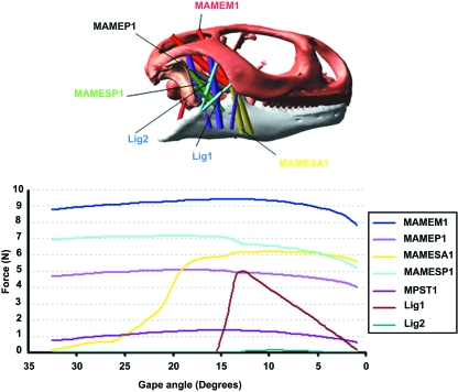
Sample muscle and ligament force data used in the MDA are presented in Fig. 1. Many of the muscle forces were relatively constant, despite the non-linear force–length relationships used in their definitions (see Moazen et al. 2008), whereas the force in others [for example, the posterior strand of the MAMESA 1 and ligament forces] gradually increases or decreases as the geometry of the model and moment arms of the muscles change with time. The muscle forces were applied to biting simulations on a viscoelastic food particle as described in Moazen et al. (2008), and provided joint, bite and ligament forces for three different bite positions, as shown in Fig. 2.
Fig. 1.
Sample muscle and ligament force data plotted vs. gape angle from MDA corresponding to an anterior bite. The MPST is an internal muscle and it is not visible in this figure.
Comparison of FEA for Models A and B
Finite element analysis produces a vast amount of data. Interpreting those data, or even presenting it in a concise way, can be difficult, and different studies often report different output parameters. The most popular are principal stresses, maximum shear stress and von Mises stress (or strain). For example, the full three-dimensional stress field at each point in the model consists of three direct stresses in the x, y and z directions and three shear stresses. These six values can be resolved into three perpendicular principal stresses (which are the normal stresses on planes which have no corresponding shear stresses). The advantage of considering the principal stresses is that they show the variation of the ‘most tensile’ and ‘most compressive’ stress through the structure and reveal information about its mode of loading. Also, very importantly, their directions show the load transfer paths through the structure. Of course, on the surface of the model, the normal stress must equal zero, thus only two principal stresses need to be considered. The mode of loading and load path information is not provided by the maximum shear stress or the von Mises stress (or strain) values. The maximum shear stress is simply half the difference between the minimum and maximum principal stresses. The von Mises stress combines all the stresses at a point into a single parameter, and is a convenient way of expressing the state of stress at that point by a single value. Like the maximum shear stress it gives no indication of whether the material is under tension or compression. In engineering analyses, both the maximum shear stress and the von Mises stress are used in the prediction of failure of ductile materials – called Tresca's failure criterion and the von Mises failure criterion, respectively (Timoshenko, 1955). As bone is a ductile material (Nalle et al. 2003), failure is not considered in most FE models of bone, and maximum shear stresses and von Mises stresses are simply used as simple scalar measures of stress level (e.g. Grosse et al. 2007; McHenry et al. 2007; Wroe et al. 2007; Moreno et al. 2008).
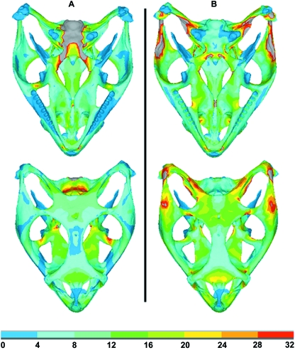
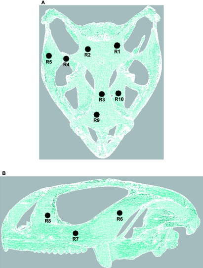
In this part of the work, von Mises stress was plotted for both Model A and Model B (as shown in Fig. 3) to get a general indication of the stress levels in the two models with an anterior bite point. In Model A high stress concentrations were observed in the basicranium in the region of the constraints; however, in Model B the stress in this region was negligible. Areas of high stress were seen in Model B at the points of muscle force application. Table 1 presents a quantitative comparison of von Mises stress between these two models over 10 selected regions whose locations are shown in Fig. 4.
Fig. 3.
Comparison of von Mises stress of two FE models in dorsal and ventral view. Both Models A and B were loaded with the same bite force (biting in front) and constraints (at the occipital condyle – see text), whereas Model B also included muscle, ligament and joint forces. Note stress values are in MPa and that grey colours indicate stresses in excess of 32 MPa.
Table 1.
Comparison of von Mises stress between Model A and Model B over the 10 selected regions. Stress values are given in MPa
| R1 | R2 | R3 | R4 | R5 | R6 | R7 | R8 | R9 | R10 | |
|---|---|---|---|---|---|---|---|---|---|---|
| Model A | 8.47 | 6.24 | 1.60 | 3.03 | 4.61 | 2.21 | 2.60 | 7.78 | 3.85 | 12.94 |
| Model B | 11.57 | 14.19 | 3.14 | 17.76 | 19.61 | 8.48 | 5.61 | 17.90 | 5.00 | 14.53 |
Fig. 4.
Location of 10 identified regions used for quantitative representation of results. (A) Ventral and (B) lateral views.
FEA of Model B
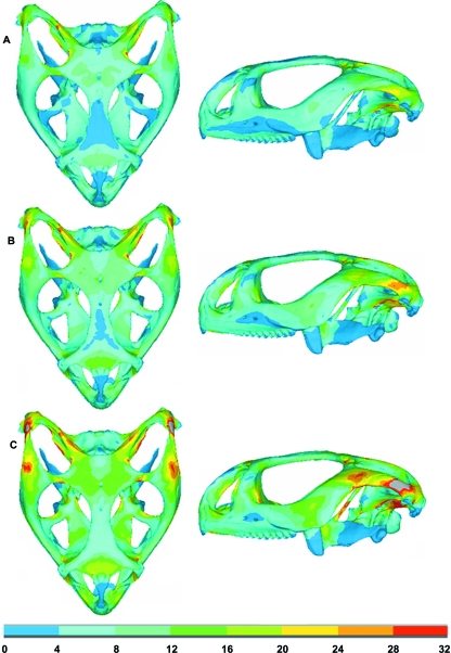
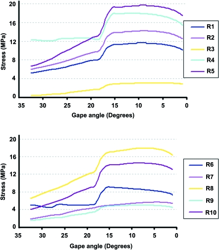
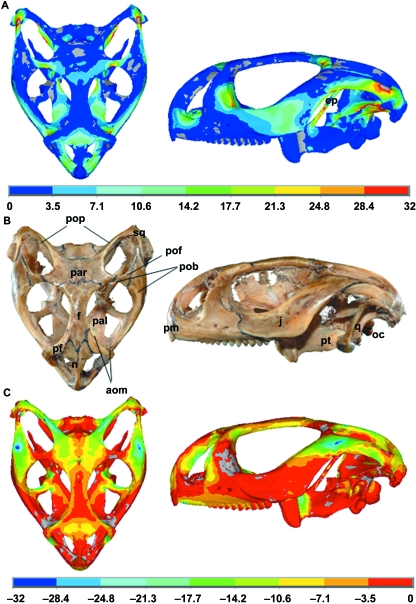
Figure 5 shows the von Mises stress distribution during bilateral biting simulation at the front of the mouth (incisiform teeth), where the stress varies as the jaw closes, corresponding to the varying loading conditions (i.e. muscle force, joint force and bite force) at different gapes. Von Mises stress was again assessed at 10 selected regions across the skull during this simulation to show how peak stress in different regions of the skull can vary (see Figs 4 and 6). Figure 7 shows a comparison between the first principal (most tensile) stress and the third principal (most compressive) stress obtained from a biting simulation in the front of the mouth (biting at gape angles of 0.9°) and a real Uromastyx lizard skull in which cranial sutures are highlighted. The first principal stress and the third principal stress are more relevant than von Mises stress for this aspect of the research. From this analysis it was noted that higher stress regions were formed near the suture locations.
Fig. 5.
Model B: ventral and lateral views showing the variation in von Mises stress during bilateral biting at the front teeth. (A–C) Biting at gape angles of 32°, 23° and 0.9°, respectively. Note stress values are in MPa and that grey colours indicate stresses in excess of 32 MPa.
Fig. 6.
Variation of von Mises stress during the biting cycle at 10 sample locations, with an anterior bite point (see Fig. 4 for locations of the sampling points).
Fig. 7.
(A) First principal (most tensile) stress. (B) Real Uromastyx skull. (C) Third principal (most compressive) stress. A comparison of the distribution of the stress predicted by the FE model with the location of the sutures in a real skull of a Uromastyx hardwickii(UCL collection) in ventral and lateral views. Note the quadrate was included in the MDA model but is not modelled in the FEA study, and hence is not shown in the FE plot. The grey colour in (A) shows values less than zero, whereas in (C) it shows values greater than zero. FE plots obtained from biting at a gape angle of 0.9° at the front of the mouth. pop, postparietal process; pof, postfrontal; pob, postorbital bar (i.e. separating orbit from temporal region); aom, antorbital margin; f, frontal; pf, prefrontal j, jugal; n, nasal; oc, occipital condyle; pal, palatine; par, parietal; pm, premaxilla; q, quadrate; sq, squamosal; ep, epipterygoid; pt, pterygoid.
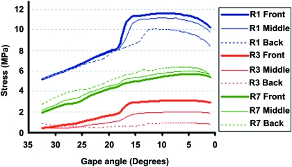
A quantitative comparison of the von Mises stress at three locations on the skull (R1, R3 and R7 see Fig. 4) was made while biting at different positions in the mouth (see Fig. 8). These three points (at the root of the left postparietal process, between the orbits, and at the root of the left postorbital bar above the end of the tooth row) were chosen to represent anterior, posterior, and lateral skull regions. The maximum variation was noted at R3, where biting at the back of the mouth led to a reduction in stress of 81% compared to the front of the mouth (front –2.96 MPa, back –0.54 MPa). A reduction of 23% was also noted at R1 (front –11.40 MPa, back –8.81 MPa), but there was a small increase in stress in R7.
Fig. 8.
Comparison of the variation in von Mises stress in three sample regions of the skull at varying bite points in the mouth.
Discussion
Methodological approaches
Multibody dynamics analysis is a powerful tool that allows many loading scenarios to be investigated, in turn providing increased data for finite element analyses (i.e. unilateral and bilateral bite forces, varying muscle loading at different gapes, etc). The main goal of this study was to apply the previously generated load data from an MDA simulation (Moazen et al. 2008) to a finite element model. Moazen et al. (2008) developed a model of jaw open/closing in Uromastyx in which the jaw was opened by defined motion data (Throckmorton, 1980), during which a mobile quadrate moved anteriorly and resulted in a slack temporal ligament. During jaw closing, muscle forces (assuming 100% activity) were applied to close the jaw against a viscoelastic food particle. This resulted in posterior movement of the quadrate to its starting position while the temporal ligament limited this backward movement by becoming tense (see Fig. 1). Movement of a food particle from the front of the mouth (incisiform tooth) to the back of the mouth (posterior teeth) showed that biting toward the back of the mouth is more effective because it leads to an increase in bite force, with a decrease in joint forces, as well as less tension in the temporal ligament (see Fig. 2).
There are currently two main methods of loading and constraining FE models of skulls in the literature. The simplest is to apply a bite force on one or more teeth on the skull, possibly with additional muscle loads, while applying rigid constraints at the occipital condyle. This ignores any reaction forces acting upon the skull via the jaw joints, and does not attempt to equilibrate the skull (e.g. Tanne et al. 1988; Miyasaka et al. 1994; Rayfield, 2005b). The second is to constrain the skull at the jaw joints and the teeth in the vertical direction while applying muscle forces directed towards their mandibular insertions (e.g. Dumont et al. 2005; Strait et al. 2005). This second method is similar to one solution step in the MDA method described above, except (1) it does not easily allow for different gape angles and changes in geometry; (2) it is time-consuming to calculate the directions of the muscle forces accurately; and (3) it is not easy to incorporate the actual physiological behaviour of the jaw joints – for example, the mobile quadrate in the Uromastyx described here, or the translation and rotation of the jaw joint observed in primate skulls. These affect the moment arms of the muscles and create more complex boundary conditions at the jaw joints.
Erroneous stress concentrations about constraints in the FEA were noted in the simple model (bite force only with constraints at the occipital condyle). These constraint stresses were not present in the MDA-loaded FEA model, as the bite and joint forces are derived in response to applied muscle forces and provide a state of equilibrium. Also, a quantitative comparison of the von Mises stress in 10 identified regions between these two models confirms that the stresses recorded from the approach that was implemented in this research are higher than in the simple model, and depending on the area of interest on the skull this can lead to significant differences (see Table 1 and Fig. 3). Stress concentrations were, however, observed in the MDA-loaded FEA model in the dorsal region of the postorbitofrontal/jugal and jugal/squamosal sutures due to the action of the muscle forces, which of course were not present in the simply loaded model. The issue of higher stresses in areas where distributed loads are applied as point loads is a common problem in all finite element analyses (because load is applied over a vanishingly small area), and has been addressed in more detail for this application by Grosse et al. (2007). An interesting finding in this study was that in the ventral view, stress distributions were similar in the nasal and frontal bones for both models, confirming that the stress in this region is predominantly due to the bite force, as expected (see Fig. 3).
Biting in Uromastyx
From Figs 5 and 6 it can be seen that stress varies throughout the skull during biting, to different degrees in different regions of the skull. This variation is due to the variation in muscle, joint and ligament forces and their respective moment arms at different gapes (see Figs 1 and 2). A sudden increase of stress between a gape angle of 20° and 15° was noted during the biting simulation (see Fig. 6). This occurs as a result of the combined increased tension in the different muscle groups at this stage of jaw closure and the resultant changes in reaction at the bite point and joint 1 (see Fig. 1– MAMESA 1; note other muscle strands, not shown, follow a similar pattern to MAMESA 1). Whether this happens as abruptly in vivo is not known, but the identification of this likely cause and effect highlights the value of MDA modelling.
One interesting finding during these FE studies is the identification of higher areas of first principal and/or third principal stress around anatomical suture zones (see Fig. 7), most notably between the prefrontal, maxilla and palatine in the antorbital margin; between the postorbitofrontals and parietal; at the junction of the nasals, prefrontals, frontal and premaxilla on the snout; around the junction of the frontal and parietal; and at the sutures between the jugal and squamosal, and jugal and postorbitofrontal. This finding suggests that sutures are located in areas of high tension/compression, and as such could act to alleviate the stress arising from biting, which agrees with previous experimental and computational studies (Herring et al. 1996; Herring & Teng, 2000; Rafferty et al. 2003; Rayfield, 2005a). Further work is now on-going to introduce sutures into these models to see whether they do indeed reduce the level of stress in these regions.
There are also high levels of stress at many of the interfaces between the braincase and the dermal skull, notably in the basipterygoid processes of the basisphenoid where they meet the pterygoids, in the paroccipital processes of the opisthotic (meeting the parietal, squamosal, supratemporal and quadrate), and in the posterior processes of the parietal. These strains may reflect the tendency of the braincase to move in relation to the skull roof and palate and thus be indicative of a selective advantage for greater freedom of movement (metakinesis). Comparison of the first and third principal stress (Fig. 7) highlights a related feature not evident in the von Mises plots, namely the high level of tension in the epipterygoids during biting in Uromastyx(Fig. 7A). In lizards, the epipterygoids are slender mobile columns. Each has a synovial ventral joint with the pterygoid (in a pit, the fossa columellae) and a ligamentous dorsal attachment to the parietal and the braincase. Where present, the epipterygoids are the origin of parts of the m. pseudotemporalis. They are thought to brace the braincase against the dermal skull when (if) one moves against the other during metakinesis, and may be absent or reduced in taxa where this movement is lost (e.g. chamaeleons, snakes, some agamids; Schwenk, 2000). The high level of tensile strain seen in our model during biting may result from direct muscle action, although (Fig. 2) the m. pseudotemporalis does not generate much force at this stage of the bite. Alternatively, like the stresses noted above, the tension in the epipterygoid may reflect a tendency of the braincase to rotate on the dermal skull during biting, pushing the pterygoids apart. In the living animal, these strains in the epipterygoid would be mitigated by its mobile dorsal and ventral articulations.
This work has also shown the importance of considering different loading scenarios, as the variation in stress across the skull varies with different load conditions. Our results agree with others who noted greater bite forces with a more posterior bite point (e.g. Koolstra et al. 1988; Dumont & Herrel, 2003; Sellers & Crompton, 2004). However, we also found that peak stress values generally tended to reduce with more posteriorly positioned food boluses, even though the bite force increased (see Figs 2 and 8). For any lizard herbivore, the primary role of the jaws and dentition is in cropping (Schwenk, 2000). Herbivorous lizards tend to have shorter, deeper jaws than insectivores (Herrel et al. 1999), with a higher mechanical advantage, and this is the pattern seen in Uromastyx. Uromastyx uses a combination of jaw closure and anteroposterior jaw movement (streptostylic quadrate) to tear off plant food and bring it into the mouth (Throckmorton, 1976), but uses jugo-mandibular ligaments to fix the quadrate in hard biting. An anterior bite, as in cropping, would induce compressive stress in the premaxilla and up through to the frontal, which it directly abuts between the nasals, to the parietal; these bones are thick and strongly united. A posterior bite would have a different force trajectory with much of the stress passing through the jugal and along the lateral aspect of the skull. The drop in strain at R3 (frontal) and, to a lesser degree, R1 (parietal) between anterior and posterior bite positions could reflect these different trajectories, as might the slight increase in strain at R7.
Limitations
As with most biomechanical simulations, there are a number of simplifications and approximations in this analysis. Probably the most significant is that we have assumed 100% activation for each muscle; this is a simple, convenient approach, but is unlikely to be physiologically accurate. For our long-term goal, to understand the structure of the skull, it may be relevant because it allows us to predict the maximum possible stress that the skull could experience, and that it is perhaps ultimately constructed to withstand. However, we aim to refine this aspect of the simulation to allow us to explore the habitual stresses experienced by the skull, rather than the exceptional. Both must affect skull development but presumably in different ways. Also in real life the position of the food particle in relation to the teeth will change during the bite cycle. Here we only consider a food particle positioned perpendicular to the teeth (both in the MDA and FEA).
The assumption of isotropy in the bone properties is also known to affect the level of stress in the bone, but not the overall distribution (Strait et al. 2005). Detailed material property values were not available for the specimen examined in this study, and would be extremely difficult to obtain due to the size of the skull. Also, the use of assumed non-isotropic material properties will introduce unquantifiable artefacts into the results. Therefore we followed the usual pragmatic approach of assuming isotropic properties (Witzel & Preuschoft, 1999; Rayfield et al. 2001; Cattaneo et al. 2003; Cruz et al. 2003; Kupczik et al. 2007; Strait et al. 2007).
Conclusions
Despite these limitations, this work demonstrates the benefits of using MDA to estimate the biomechanical loads for application to FE models of skulls. We feel this is the best way to properly test hypotheses in functional morphology in a more objective way, where muscle data, joint data and bite data can all be obtained and then applied to calculate stress and strains throughout the skull. More work is required to improve the complexity and realism of both the MDA and FEA models, but the results shown here demonstrate the effects of different bite positions on patterns of strain in the lizard skull, suggest a selective advantage for the elaboration of joints involved in relative movements of the braincase against the dermal skull, and provide evidence of a functional role for cranial sutures. Additional loading scenarios need to be considered in the MDA, such as unilateral biting, and in the FEA the inclusion of sutures and anisotropic material properties would allow more accurate stress and strain results.
Acknowledgments
The authors thank Mehrdad Moazen for his support, Jessie Maisano, University of Texas, Austin, Digimorph Laboratory, for the microCT data of the Uromastyx, and Mike Park for photographing our specimens. We also gratefully acknowledge the financial support of BBSRC.
References
- Cattaneo PM, Dalstra M, Melsen B. The transfer of occlusal forces through the maxillary molars: a finite-element study. Am J Orthod Dentofacial Orthop. 2003;123:367–373. doi: 10.1067/mod.2003.73. [DOI] [PubMed] [Google Scholar]
- Cruz M, Wassall T, Toledo EM, Barra LP, Lemonge AC. Three-dimensional finite-element stress analysis of a cuneiform-geometry implant. Int J Oral Maxillofac Implants. 2003;18:675–684. [PubMed] [Google Scholar]
- Curtis N, Kupczik K, O’Higgins P, Moazen M, Fagan MJ. Predicting skull loading: applying multibody dynamics analysis to a Macaque skull. Anat Rec. 2008;291:491–501. doi: 10.1002/ar.20689. [DOI] [PubMed] [Google Scholar]
- Dumont ER, Herrel A. The effect of gape angle and bite point on bite force in bats. J Exp Biol. 2003;206:2117–2123. doi: 10.1242/jeb.00375. [DOI] [PubMed] [Google Scholar]
- Dumont ER, Piccirillo J, Grosse IR. Finite-element analysis of biting behaviour and bone stress in the facial skeletons of bats. Anat Rec. 2005;283A:319–30. doi: 10.1002/ar.a.20165. [DOI] [PubMed] [Google Scholar]
- El-Toubi MR. Notes on the cranial osteology of Uromastyx aegyptia(Forskål) Bull Fac Sci Cairo Faud 1 Univ. 1945;25:1–10. [Google Scholar]
- Fagan MJ. Finite Element Analysis – Theory and Practice. Harlow: Longmans; 1992. [Google Scholar]
- George JC. On the cranial osteology of Uromastix hardwickii(Gray) J Anim Morphol Physiol. 1955;1:23–29. [Google Scholar]
- Geradin M, Cardona A. Flexible Multibody Dynamics: A Finite Element Approach. New York: J Wiley & Sons; 2001. [Google Scholar]
- Grosse IR, Dumont ER, Coletta C, Tolleson A. Techniques for modeling muscle-induced forces on finite element models of skeletal structures. Anat Rec. 2007;290:1069–1088. doi: 10.1002/ar.20568. [DOI] [PubMed] [Google Scholar]
- Hannam AG. Dynamic modeling and jaw biomechanics. Orthod Craniofac Res. 2003;6:59–65. doi: 10.1034/j.1600-0544.2003.236.x. [DOI] [PubMed] [Google Scholar]
- Herrel A, Aerts P, Fret J, De Vree F. Morphology of the feeding system in agamid lizards: ecological correlates. Anat Rec. 1999;254:496–507. doi: 10.1002/(SICI)1097-0185(19990401)254:4<496::AID-AR5>3.0.CO;2-Q. [DOI] [PubMed] [Google Scholar]
- Herring SW, Teng SY. Strain in the braincase and its sutures during function. Am J Phys Anthropol. 2000;112:575–593. doi: 10.1002/1096-8644(200008)112:4<575::AID-AJPA10>3.0.CO;2-0. [DOI] [PMC free article] [PubMed] [Google Scholar]
- Herring SW, Teng SY, Huang XF, Mucci RJ, Freeman J. Patterns of bone strain in the zygomatic arch. Anat Rec. 1996;246:446–457. doi: 10.1002/(SICI)1097-0185(199612)246:4<446::AID-AR4>3.0.CO;2-T. [DOI] [PubMed] [Google Scholar]
- Hill AV. The heat of shortening and the dynamic constants of muscle. Proc R Soc Lond B Biol Sci. 1938;126:136–195. doi: 10.1098/rspb.1949.0019. [DOI] [PubMed] [Google Scholar]
- Islam A. The skull of Uromastix hardwickiiGray. Biologia (Lahore) 1955;1:141–196. [Google Scholar]
- Koolstra JH, van Eijden TMGJ. Combined finite-element and rigid-body analysis of human jaw joint dynamics. J Biomech. 2005;38:2431–2439. doi: 10.1016/j.jbiomech.2004.10.014. [DOI] [PubMed] [Google Scholar]
- Koolstra JH, van Eijden TMGJ. Prediction of volumetric strain in the human temporomandibular joint cartilage during jaw movement. J Anat. 2006;209:369–380. doi: 10.1111/j.1469-7580.2006.00612.x. [DOI] [PMC free article] [PubMed] [Google Scholar]
- Koolstra JH, van Eijden TMGJ, Weijs WA, Naejie M. A three-dimensional mathematical model of the human masticatory system predicting maximum possible bite forces. J Biomech. 1988;21:563–576. doi: 10.1016/0021-9290(88)90219-9. [DOI] [PubMed] [Google Scholar]
- Kupczik K, Dobson CA, Fagan MJ, Crompton RH, Oxnard CE, O’Higgins P. Assessing mechanical function of the zygomatic region in macaques: validation and sensitivity testing of finite element models. J Anat. 2007;210:41–53. doi: 10.1111/j.1469-7580.2006.00662.x. [DOI] [PMC free article] [PubMed] [Google Scholar]
- Langenbach GEJ, Zhang F, Herring SW, Hannam AG. Modelling the masticatory biomechanics of a pig. J Anat. 2002;201:383–393. doi: 10.1046/j.0021-8782.2002.00108.x. [DOI] [PMC free article] [PubMed] [Google Scholar]
- McHenry C, Wroe S, Clausen P, Moreno K, Cunningham E. Super-modeled sabercat, predatory behaviour in Smilodon fatalis revealed by high-resolution 3-D computer simulation. Proc Natl Acad Sci U S A. 2007;104:16010–16015. doi: 10.1073/pnas.0706086104. [DOI] [PMC free article] [PubMed] [Google Scholar]
- Miyasaka J, Tanne K, Nakamura S. Finite element analysis for stresses in the craniofacial sutures produced by maxillary protraction forces applied at the upper canines. Br J Orthod. 1994;21:343–348. doi: 10.1179/bjo.21.4.343. [DOI] [PubMed] [Google Scholar]
- Moazen M, Curtis N, Evans SE, O’Higgins P, Fagan MJ. Rigid-body analysis of the lizard skull: modelling the skull of Uromastyx hardwickii. J Biomech. 2008;41:1274–1280. doi: 10.1016/j.jbiomech.2008.01.012. [DOI] [PubMed] [Google Scholar]
- Moreno K, Wroe S, Clausen P, et al. Cranial performance in the Komodo dragon (Varanus komodoensis) as revealed by high-resolution 3-D finite element analysis. J Anat. 2008;212:736–746. doi: 10.1111/j.1469-7580.2008.00899.x. [DOI] [PMC free article] [PubMed] [Google Scholar]
- Nalle RK, Kinney JH, Ritchie RO. Mechanistic fracture criteria for the failure of human cortical bone. Nat Mater. 2003;2:164–168. doi: 10.1038/nmat832. [DOI] [PubMed] [Google Scholar]
- Preuschoft H, Witzel U. The functional shape of the human skull, as documented by three-dimensional FEM studies. Anthropol Anz. 2002;60:113–135. [PubMed] [Google Scholar]
- Preuschoft H, Witzel U. Functional shape of the skull in vertebrates: which forces determine skull morphology in lower primates and ancestral synapsids? Anat Rec. 2005;283A:402–413. doi: 10.1002/ar.a.20176. [DOI] [PubMed] [Google Scholar]
- Rafferty KL, Herring SW, Marshall CD. Biomechanics of the rostrum and the role of facial sutures. J Morphol. 2003;257:33–44. doi: 10.1002/jmor.10104. [DOI] [PMC free article] [PubMed] [Google Scholar]
- Rayfield EJ. Using finite-element analysis to investigate suture morphology: a case study using large carnivorous dinosaurs. Anat Rec. 2005a;283A:349–365. doi: 10.1002/ar.a.20168. [DOI] [PubMed] [Google Scholar]
- Rayfield EJ. Aspects of comparative cranial mechanics in the theropod dinosaurs Coelophysis, Allosaurus and Tyrannosaurus. Zool J Linnean Soc. 2005b;144:309–316. [Google Scholar]
- Rayfield EJ. Finite element analysis and understanding the biomechanics of evolution of living and fossil organisms. Annu Rev Earth Planet Sci. 2007;35:541–576. [Google Scholar]
- Rayfield EJ, Norman DB, Horner CC, et al. Cranial design and function in a large theropod dinosaur. Nature. 2001;409:1033–1037. doi: 10.1038/35059070. [DOI] [PubMed] [Google Scholar]
- Richmond BG, Wright BW, Grosse I, et al. Finite element analysis in functional morphology. Anat Rec. 2005;283A:259–274. doi: 10.1002/ar.a.20169. [DOI] [PubMed] [Google Scholar]
- Ross CF, Patel BA, Slice DE, et al. Modeling masticatory muscle force in finite element analysis: sensitivity analysis using principal coordinates analysis. Anat Rec. 2005;283A:288–299. doi: 10.1002/ar.a.20170. [DOI] [PubMed] [Google Scholar]
- van Ruijven LJ, Weijs WA. A new model for calculating muscle forces from electromyograms. Eur J Appl Physiol. 1990;61:479–485. doi: 10.1007/BF00236071. [DOI] [PubMed] [Google Scholar]
- Saksena RD. The bony palate of UromastixMerrem. Proc Ind Acad Sci B. 1942;16:107–119. [Google Scholar]
- Schwenk K. Feeding in lepidosaurs. In: Schwenk K, editor. Feeding: Form, Function and Evolution in Tetrapod Vertebrates. San Diego: Academic Press; 2000. pp. 175–291. [Google Scholar]
- Sellers WI, Crompton RH. Using sensitivity analysis to validate the predictions of a biomechanical model of bite forces. Ann Anat. 2004;185:89–95. doi: 10.1016/S0940-9602(04)80132-8. [DOI] [PubMed] [Google Scholar]
- Strait DS, Wang Q, Dechow PC, et al. Modeling elastic properties in finite element analysis: How much precision is needed to produce an accurate model? Anat Rec. 2005;283A:275–287. doi: 10.1002/ar.a.20172. [DOI] [PubMed] [Google Scholar]
- Strait DS, Richmond BG, Spencer MA, Ross CF, Dechow PC, Wood BA. Masticatory biomechanics and its relevance to early hominid phylogeny: An examination of palatal thickness using finite-element analysis. J Hum Evol. 2007;52:585–599. doi: 10.1016/j.jhevol.2006.11.019. [DOI] [PubMed] [Google Scholar]
- Tanne K, Miyasaka J, Yamagata Y, Sachdeva R, Tsutsumi S, Sakuda M. Three-dimensional model of the human craniofacial skeleton: method and preliminary results using finite element analysis. J Biomed Eng. 1988;10:246–252. doi: 10.1016/0141-5425(88)90006-4. [DOI] [PubMed] [Google Scholar]
- Throckmorton GS. Oral food processing in two herbivorous lizards, Iguana iguana(Iguanidae) and Uromastix aegyptius(Agamidae) J Morphol. 1976;148:363–390. doi: 10.1002/jmor.1051480307. [DOI] [PubMed] [Google Scholar]
- Throckmorton GS. The chewing cycle in the herbivorous lizard Uromastix aegyptius(Agamidae) Arch Oral Biol. 1980;25:225–233. doi: 10.1016/0003-9969(80)90027-8. [DOI] [PubMed] [Google Scholar]
- Timoshenko SP. Strength of Materials: Part 1: Elementary Theory and Problems. New York: Van Nostrand; 1955. [Google Scholar]
- Wang Q, Dechow PC. Elastic properties of external cortical bone in the craniofacial skeleton of the rhesus monkey. Am J Phys Anthropol. 2006;131:402–415. doi: 10.1002/ajpa.20438. [DOI] [PubMed] [Google Scholar]
- Witzel U, Preuschoft H. The bony roof of the nose in humans and other primates. Zool Anz. 1999;238:103–115. [Google Scholar]
- Wroe S, Moreno K, Clausen P, McHenry C, Curnoe D. High resolution computer simulation of hominid cranial mechanics. Anat Rec. 2007;290:1248–1255. doi: 10.1002/ar.20594. [DOI] [PubMed] [Google Scholar]
- de Zee M, Dalstra M, Cattaneo PM, Rasmussen J, Svensson P, Melsen B. Validation of a musculo-skeletal model of the mandible and its application to mandibular distraction osteogenesis. J Biomech. 2007;40:1192–1201. doi: 10.1016/j.jbiomech.2006.06.024. [DOI] [PubMed] [Google Scholar]


