

Abstract
Objective
To compare measurements from synthesized cone-beam computed tomography (CBCT) lateral cephalograms using orthogonal and perspective projections with those from conventional cephalometric radiographs.
Materials and Methods
Thirty-one patients were imaged using CBCT and conventional cephalometry. CBCT volume data were imported in Dolphin 3D. Orthogonal and perspective lateral cephalometric radiographs were created from three-dimensional (3D) virtual models. Twelve linear and five angular measurements were made on synthesized and conventional cephalograms in a randomized fashion. Conventional image measurements were corrected for known magnification. Linear and angular measurements were compared between image modalities using repeated measures analysis of variance. Statistical significance was defined as an α level of .01.
Results
With the exception of the Frankfort-mandibular plane angle (P < .0001), angular measurements were not statistically different for any modality (P > .01). Linear measurements, whether based on soft or hard tissue landmarks, were not statistically different (P > .01).
Conclusions
Measurements from in vivo CBCT synthesized cephalograms are similar to those based on conventional radiographic images. Thus, additional conventional imaging may generally be avoided when CBCT scans are acquired for orthodontic diagnosis.
Keywords: Cephalometry, Cone-beam computed tomography, X-ray computed tomography
INTRODUCTION
Cephalometry is an essential clinical and research tool in orthodontics. It has been used for decades to obtain absolute and relative measures of the craniofacial skeleton. Lateral cephalograms are two-dimensional (2D) radiographs that are used to depict three-dimensional (3D) structures. Consequently, cephalograms have inherent limitations as a result of distortion and differential magnification of the craniofacial complex. This may lead to errors of identification and reduced measurement accuracy.1-3
Three-dimensional imaging techniques are becoming increasingly popular and have opened new possibilities for orthodontic diagnosis and treatment assessment.4 Despite the usefulness of computed tomography (CT), the high cost and relatively high radiation exposure make this modality unsuitable for orthodontic purposes.5
The introduction of maxillofacial cone beam CT (CBCT) has made 3D imaging more readily available for dental applications. The advantages of CBCT over CT include low radiation dose, lower cost, potentially better access, and high spatial resolution.6-8 While 3D analysis for diagnosis and treatment undergoes clinical validation, 2D image simulation tools may be used on 3D volumes and can help bridge the gap between 2D and 3D image types. CBCT image data can be used to simulate panoramic, lateral, and posteroanterior cephalometric radiographs so that they can be compared with preexisting image databases.9,10
A previous study suggested that measurements from CBCT synthesized cephalograms are similar to those from conventional cephalograms in vitro.11 The purpose of this study was to determine whether CBCT synthesized cephalograms provide the same measurement as conventional cephalograms when applied to patients. The specific aims were to test the null hypotheses that cephalometric measurements are not different for conventional cephalometric radiographs and synthesized CBCT cephalograms using either perspective or orthogonal reconstruction algorithms.
MATERIALS AND METHODS
Thirty-one patients (13 male, 18 female; 21.6 ± 7.9 years) treated in the Dentofacial Deformities Program at the School of Dentistry were recruited for this study. Informed consent was obtained from all subjects, and the study was approved by the Institutional Review Board.
Conventional cephalograms were acquired by positioning the patients in a cephalostat in natural head position (Wehmer Cephalostat, Addison, Ill). The source-midsagittal plane distance was 152.4 cm (5 feet). A photostimulable phosphor plate was used as the detector and positioned 11.5 cm from the midsagittal plane. The plate was scanned at 300 dpi (Digora PCT, Soredex USA, Milwaukee, Wis).
CBCT scans were made before orthognathic surgery with the NewTom 3G (AFP Imaging, Elmsford, NY). The imaging protocol used a 12-in field of view to include the entire facial anatomy. The axial slice thickness was 0.3 mm, and the voxels were isotropic. The axial images were imported in Dolphin 3D (pre-release version 1, Dolphin Imaging & Management Systems, Chatsworth, Calif). Although the Dolphin imaging software has been constantly updated, the updated features refer to improvement of 3D rendering algorithms and functionality. The Dolphin version used in this study uses the same procedures as the current version of Dolphin 10 to generate radiographic images and 2D cephalometric tracing and analysis. A 3D virtual model was created from the study and carefully oriented to generate the 2D cephalogram. Using axial, coronal, and sagittal views, the midsagittal plane of the model was oriented vertically, the transporionic line was oriented horizontally and the Frankfort horizontal plane was oriented horizontally (Figure 1).
Figure 1.
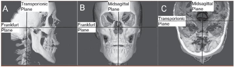
Orientation of the three-dimensional virtual model to generate the cephalograms.
An angle-measuring instrument (Original True Angle, Quint Measuring Systems, San Ramon, Calif) was used to simulate the conventional cephalogram orientation. One scale of the instrument was placed parallel to the monitor screen, and the other scale was placed touching the most prominent points of the patient’s mid-frontal bone and the mid-symphyseal region of the mandible in the conventional cephalogram. The angle was reproduced on the right sagittal view of the 3D virtual model in Dolphin 3D.
Next, orthogonal and perspective radiographs were built from the reoriented model (Figure 2). The orthogonal projection was created by parallel rays. Perspective radiographs were created simulating the geometry of the conventional cephalometric radiographs with the midsagittal plane of the patient corrected for 1:1 measurement. Measurements for conventional cephalograms were adjusted for the 7.5% midsagittal magnification.
Figure 2.
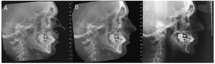
Subject exhibiting severe mandibular asymmetry: (A) orthogonal cone-beam computed tomography projection without magnification; (B) perspective projection with 7.5% simulated magnification; (C) conventional cephalogram with inherent magnification of 7.5%.
Dolphin imaging software (version 9.0.00.24) was used for cephalometric tracings of the 2D images. This study compared 12 linear and 5 angular measurements based on soft- and hard-tissue landmarks (Table 1). The measurements were selected to include both vertical and anteroposterior components of the craniofacial form. The landmarks on which these measurements were based represented both midsagittal and bilateral anatomic structures with different degrees of identification difficulty. The measurements were made by a single operator (Vandana Kumar) in a randomized fashion.
Table 1.
Measurements Used in the Studya
| Linear Measurements | Angular Measurements |
|---|---|
| LFH: Lower face height (ANS-Me) | SNA: Sella-nasion-A |
| UFH: Upper face height (N-ANS) | SNB: Sella-nasion-B |
| TFH: Total anterior face height (N-Me) | FMA: Frankfort-mandibular plane angle |
| MnL: Mandibular unit length (Co-Gn) | USN: Upper incisor-sella/nasion |
| MxL: Maxillary unit length (Co-ANS) | LMP: Lower incisor-mandibular plane |
| AN: A to N with respect to true vertical | |
| BN: B to N with respect to true vertical | |
| PgN: Pg to N with respect to true vertical | |
| OJT: Overjet | |
| ST(LN): Lower lip to N with respect to true vertical (soft tissue) | |
| ST(UN): Upper lip to N with respect to true vertical (soft tissue) | |
| ST(PgN): Pg to N with respect to true vertical (soft tissue) |
ANS indicates anterior nasal spine; Me, menton; N, nasion; Co, condylion; Gn, gnathion; Pg, pogonion; A, point A; B, point B; S, sella; Go, gonion; Frankfort, Frankfort horizontal plane; MP, mandibular plane (Me-Go); ST, soft tissue landmark.
Reproducibility of the measurement techniques used in this study was validated in a previous study of 10 dry skulls.11 Measurements made by the same examiner using the same protocol as the current study were made three times with a week’s separation between measurement sessions. When assessed with multivariate repeated measures analysis of variance (MANOVA), no statistical difference was found between repeated measurements (P > .05).
Statistical Analysis
MANOVA was used to compare the three radiographic modalities for each measurement. Because multiple measurements were investigated, the risk of a type I error is increased. Although the Bonferroni correction for multiple comparisons would suggest an alpha level of .003 for a two-tailed test, a more liberal alpha level of .01 was selected. For pairings of each modality and each measurement, the percentage of measurements within ±2 mm or 2° is also reported. This is provided as a potential threshold for clinically meaningful differences.
RESULTS
Table 2 shows that the three cephalometric modalities were not statistically different for any of the 12 linear measurements. The percent of errors within ±2 mm is noted for pairings of each modality. Table 3 shows that a statistical difference between cephalometric modalities was only present for Frankfort-mandibular plane angle (FMA) (P < .0001). Only 16% of comparisons of perspective CBCT and conventional or orthogonal CBCT and conventional were within ±2° for this measurement.
Table 2.
Differences between Linear Measurements (mm) from Three Imaging Modalitiesa
| Conventional – Orthogonal CBCT |
Perspective CBCT – Orthogonal CBCT |
Perspective CBCT – Conventional |
MANOVA |
|||||||
|---|---|---|---|---|---|---|---|---|---|---|
| Measurementb | Mean | SD | % Within ±2 mm | Mean | SD | % Within ±2 mm | Mean | SD | % Within ±2 mm | P > F |
| LFH | −0.95 | 1.88 | 58% | 0.04 | 1.90 | 87% | 0.99 | 2.84 | 58% | .0331 |
| UFH | 0.56 | 2.44 | 71% | 0.65 | 2.70 | 55% | 0.09 | 1.94 | 77% | .3903 |
| TFH | −0.80 | 2.62 | 48% | 0.42 | 3.38 | 58% | 1.23 | 3.22 | 39% | .0848 |
| MnL | −1.39 | 2.57 | 45% | −0.82 | 3.56 | 55% | 0.57 | 3.51 | 45% | .0220 |
| MxL | 2.21 | 4.71 | 35% | 0.43 | 5.38 | 39% | −1.78 | 4.09 | 39% | .0135 |
| AN | 1.15 | 3.59 | 52% | 0.78 | 2.55 | 68% | −0.37 | 3.41 | 48% | .1460 |
| BN | −0.26 | 4.16 | 45% | −0.03 | 2.15 | 65% | 0.23 | 4.07 | 55% | .9417 |
| PgN | −0.12 | 4.29 | 42% | 0.16 | 2.27 | 65% | 0.28 | 4.60 | 39% | .9120 |
| OJT | 0.25 | 1.47 | 90% | 0.08 | 0.93 | 97% | −0.17 | 1.33 | 84% | .6595 |
| ST(LN) | 0.76 | 3.39 | 61% | 0.03 | 1.75 | 71% | −0.73 | 3.38 | 65% | .5843 |
| ST(UN) | 1.45 | 3.33 | 68% | −0.15 | 1.40 | 81% | −1.61 | 3.30 | 65% | .0427 |
| ST(PgN) | 0.77 | 4.13 | 52% | 0.03 | 2.31 | 61% | −0.74 | 4.14 | 65% | .5843 |
Conventional indicates conventional cephalograms adjusted for magnification; perspective CBCT, synthesized cone-beam CT cephalograms with perspective projection adjusted for magnification; orthogonal CBCT, synthesized cone-beam CT cephalograms with orthogonal projection.
LFH indicates lower face height; UFH, upper face height; MnL, mandibular unit length; MxL, maxillary unit length; AN, A to N with respect to true vertical; BN, B to N with respect to true vertical; PgN, pogonion to N with respect to true vertical; OJT, overjet; ST(LN), lower lip to N with respect to true vertical (soft tissue); ST(UN), upper lip to N with respect to true vertical (soft tissue); ST(PgN), pogonion to N with respect to true vertical (soft tissue).
Table 3.
Differences between Angular Measurements (degrees) from Three Imaging Modalitiesa
| Conventional – Orthogonal CBCT |
Perspective CBCT – Orthogonal CBCT |
Perspective CBCT – Conventional |
MANOVA |
|||||||
|---|---|---|---|---|---|---|---|---|---|---|
| Measurementb | Mean | SD | % Within ±2° | Mean | SD | % Within ±2° | Mean | SD | % Within ±2° | P > F |
| SNA | 0.91 | 3.06 | 61% | 0.35 | 3.31 | 55% | −0.56 | 2.31 | 68% | .1932 |
| SNB | −0.37 | 1.55 | 84% | −0.48 | 1.67 | 84% | −0.11 | 1.52 | 87% | .2701 |
| FMA | 4.09* | 3.43 | 16% | −0.27 | 2.27 | 68% | −4.36* | 3.84 | 16% | <.0001 |
| USN | −1.29 | 7.49 | 29% | −0.35 | 6.66 | 32% | 0.94 | 5.23 | 42% | .5488 |
| LMP | −0.46 | 3.82 | 39% | −1.05 | 2.96 | 52% | −0.58 | 3.74 | 48% | .1718 |
Conventional indicates conventional cephalograms adjusted for magnification; perspective CBCT, synthesized cone-beam CT cephalograms with perspective projection adjusted for magnification; orthogonal CBCT, synthesized cone-beam CT cephalograms with orthogonal projection.
SNA indicates sella-nasion-A; SNB indicates sella-nasion-B; FMA, Frankfort-mandibular plane angle; USN, upper incisor-sella/nasion; LMP, lower incisor-mandibular plane.
DISCUSSION
Cephalometry is a valuable tool for diagnosing skeletal imbalance and for assessing growth, response to treatment, and long-term stability after orthodontic treatment. Cephalometric evaluation of patients with orthodontic needs has traditionally been performed by lateral and frontal cephalograms. These methods are well established and have resulted in several large databases of clinically normal and treated patient populations. Since standard population norms are not available for 3D CBCT volumes, patients for whom CBCT data are acquired may be subjected to further radiation exposure for the acquisition of traditional lateral cephalograms and panoramic radiographs. Unlike conventional cephalograms, CT has no inherent distortion of anatomic structures. As a result, more accurate measurements have been reported for planar 2D CT images.12
The current study was undertaken to determine whether traditional radiographic projections can be synthesized from CBCT volumes and whether traditional cephalometry can be done on these synthesized views with similar results. While much work is needed to demonstrate the added value of CBCT in standard orthodontic cases, it is not known whether data obtained from synthesized CBCT views can be compared with current population norms and existing databases obtained from conventional cephalograms. Because synthesized views discard much of the 3D information embedded in CBCT image volumes, the demonstration of correspondence between CBCT and conventional radiography is useful during this transition period.
The results of the current study show that the linear measurements of the three imaging modalities were not statistically different. None of the angular measurements were statistically significant except for the FMA. Every system has various sources of display and measurement inaccuracy.
In this study, only projection as a source of variability was explored, but other sources, such as landmark definition, observer variability in landmark identification, and the ability to digitize the landmarks, were not investigated. The cephalometric literature reveals that the landmarks like condylion, porion, and gonion, which are used to define the Frankfort horizontal plane and the mandibular plane, have greater margins of error.13,14 The literature shows that superimposition of the bilateral middle ear and other temporal fossa structures make it difficult to identify the anatomic porion and thus influenced the measurement of FMA angle.15 Landmarks like gonion and condylion are located on curved surfaces and are thus difficult to identify accurately.16 These various sources of noise might have influenced some of the measurements.
Although FMA is defined by the cephalometric landmarks menton, gonion, porion, and orbitale, it appears unlikely that identification of menton and gonion contributed greatly to the significant difference between images seen in this study. This is because lower incisor-mandibular plane (LMP), another angular measurement dependent on the identification of menton and gonion, was not significantly different for the different projections. Mean angular differences between techniques were less than 1.1° for LMP while mean differences rose to 4.1° for comparisons of conventional to orthogonal CBCT and 4.4° for comparisons of perspective CBCT to conventional for FMA.
Several studies showed that inconsistency in landmark identification is an inherent cause of errors in conventional cephalometry.17,18 Bruntz et al19 indicated that the face height (FH) plane is unreliable in identification with digital media. The results of their study showed that the landmarks like porion, articulare, PNS, and UM have lower reliability in landmark identification as observed from interobserver error. Thus, porion and orbitale (the two landmarks contributing to FH plane) showed significant unreliability in landmark identification. Chen et al20 showed discrepancies in the vertical component when identifying the landmarks porion, orbitale, and gnathion on digital media. In this study, the description of porion for conventional cephalometric images includes a caveat: when anatomic porion is indeterminate, the most superior point of the ear rod is used as a surrogate. As the location of the ear rods and the osseous periphery of the ear canal do not always coincide, this may have been an important source of error.
Figure 1 illustrates the effect of the application of the operational definition of porion. Although anatomic porion is indeterminate in the conventional image, it is clear that the use of ear-rod porion as a substitute is likely to be inaccurate. The presence of anatomic condylion in a superior position to porion would be an aberration. In this case, use of ear-rod porion results in overestimation of the actual FMA in the conventional cephalogram. Although the CBCT projections provide a more accurate identification of porion, this is paradoxically undesirable to the degree that it deviates from systematic (definitional) misidentification in conventional cephalograms. Keep in mind that the point of producing a cephalometric reconstruction from the CBCT volume in this study was to duplicate the characteristics of the conventional cephalogram rather than to improve on its accuracy. Although cephalostats are not used in CBCT imaging, it would be possible to place ear plugs in the patient’s ear canals to simulate the appearance of cephalostat ear rods. This would permit the use of an ear-rod determined porion if so desired.
When the percentage of data within ±2° is examined, some of the angular measures, such as USN and LMP, and some of linear measurements, such as TFH, MnL, MxL and PgN, have less than 50% of its measures within this range. In general, ±2 mm may be clinically significant for short distances and less important over long distances. Tng et al21 have also shown that validity errors were greater for angles involving dental landmarks and for angles dependent on four landmarks compared with those dependent on three. The standard deviations of the validity errors for the dental angles ranged from 3.2 to 5.8°.
Perspective imaging geometry leads to imperfect superimposition of bilateral structures. This is true for conventional cephalometric projections and perspective reconstructions of CBCT volumes. Although measurement differences related to projection distortion of bilateral structures could be hypothesized, this study showed no significant difference for measurements involving condylion and gonion between orthogonal CBCT, perspective CBCT, and conventional cephalometric images. This is consistent with the observation of Lascala and coauthors22 that CBCT technique is reliable for use in a variety of clinical situations where linear measurements between anatomic sites are required.
Patient positioning is considered critical for cephalometric analysis.18,23 The purpose of the cephalostat is to minimize projection errors caused by head rotation around the vertical, transverse, and anteroposterior axes. The problem usually encountered while taking the conventional cephalogram is that even when the cephalostat is properly adjusted, it cannot prevent slight translation or rotation of the patient’s midsagittal plane. These variations in patient position may lead to variation in cephalometric measurements.23-27
Although 3D measurements of CBCT volumes are free from the influence of patient position during image acquisition, the orientation of the secondary reconstruction of the volume directly affects the projection of anatomy in synthesized 2D cephalometric views. To remove potential sources of measurement error in the synthesized views, the orientation of the CT volume was corrected by iterative adjustment and reassessment and the natural head position was simulated by using the angle instrument. The alignment of the transporionic axis using the 3D rendered volumes was sufficiently accurate to preclude differences in identification and measurement of the landmarks used in this study. The ability to reorient the volume means that cephalostat errors, which are common to conventional cephalometry, can be eliminated in equivalent CBCT projections.
Although natural head position can be reproduced in CBCT volumes, it is debatable whether natural head position can be produced during actual positioning of the patient during CBCT imaging. This problem is obvious for an imaging protocol where the patient must be supine during image acquisition. Less obvious, but still problematic, is the situation where a seated or standing patient must be stabilized in a head holder to reduce the risk of motion artifacts. Typically, CBCT unit restraints and guides are not designed to promote natural head position. Alternative approaches for orienting patients’ volumes will be required in the future. Use of defined anatomic references, such as the Frankfort plane, is an obvious solution for standardization of images. Alternatively, CT volumes may be registered with either 2D or 3D photographic images of the patient in natural head position. This type of registration is now routinely done with CT and MR (Magnetic Resonance) imaging volumes.
This study uses one of the commercially available tools (Dolphin 3D) for generating and measuring cephalograms from CBCTs. While our study systematically assesses measurements with the synthesized cephalograms, the software used is much more user friendly than the scanner’s current software, allowing for improved image quality. Current 3D image analysis software is continuously being updated. Other commercial tools, such as the Invivo software (Anatomage, San Jose, Calif), also have algorithms that render 2D radiographs with postprocessing filters to aid identification of anatomic details. Additional studies are needed to evaluate the parameters of 2D image generation using diverse tools.
The statistically significant difference between the values of one of the angle measurements of synthesized projections compared with conventional lateral views requires further investigation. Although these differences were relatively small, they could be clinically relevant.
CONCLUSIONS
Synthesized cephalometric images from CBCT may be used to bridge the transition from 2D to 3D image analysis.
Both types of synthesized CBCT projections are similar to conventional cephalograms. In cases where landmarks such as porion are visually ambiguous and necessitate the use of proxy landmarks such as the ear rods, CBCT cephalometric images may provide a more accurate delineation of the landmark resulting in different measurements from those obtained from conventional cephalograms.
In other cases, CBCT cephalometric image reconstruction can be recommended as an alternative to conventional cephalograms when a CBCT volume is already available, thus reducing the need for additional x-ray exposure and examination expense.
References
- 1.Ahlqvist J, Eliasson S, Welander U. The effect of projection errors on cephalometric length measurements. Eur J Orthod. 1986;8:141–148. doi: 10.1093/ejo/8.3.141. [DOI] [PubMed] [Google Scholar]
- 2.Baumrind S, Frantz RC. The reliability of head film measurements. 1. Landmark identification. Am J Orthod. 1971;60:111–127. doi: 10.1016/0002-9416(71)90028-5. [DOI] [PubMed] [Google Scholar]
- 3.Baumrind S, Frantz RC. The reliability of head film measurements. 2. Conventional angular and linear measures. Am J Orthod. 1971;60:505–517. doi: 10.1016/0002-9416(71)90116-3. [DOI] [PubMed] [Google Scholar]
- 4.Danforth RA, Dus I, Mah J. 3-D volume imaging for dentistry: a new dimension. J Calif Dent Assoc. 2003;31:817–823. [PubMed] [Google Scholar]
- 5.Ekestubbe A, Thilander A, Grondahl K, Grondahl HG. Absorbed doses from computed tomography for dental implant surgery: comparison with conventional tomography. Dentomaxillofac Radiol. 1993;22:13–17. doi: 10.1259/dmfr.22.1.8508935. [DOI] [PubMed] [Google Scholar]
- 6.Ludlow JB, Davies-Ludlow LE, Brooks SL. Dosimetry of two extraoral direct digital imaging devices: NewTom cone beam CT and Orthophos Plus DS panoramic unit. Dentomaxillofac Radiol. 2003;32:229–234. doi: 10.1259/dmfr/26310390. [DOI] [PubMed] [Google Scholar]
- 7.Sukovic P. Cone beam computed tomography in craniofacial imaging. Orthod Craniofac Res. 2003;6(suppl 1):31–36. doi: 10.1034/j.1600-0544.2003.259.x. discussion 179–182. [DOI] [PubMed] [Google Scholar]
- 8.Farman AG, Scarfe WC. Development of imaging selection criteria and procedures should precede cephalometric assessment with cone-beam computed tomography. Am J Orthod Dentofacial Orthop. 2006;130:257–265. doi: 10.1016/j.ajodo.2005.10.021. [DOI] [PubMed] [Google Scholar]
- 9.Cevidanes LH, Styner MA, Proffit WR. Image analysis and superimposition of 3-dimensional cone-beam computed tomography models. Am J Orthod Dentofacial Orthop. 2006;129:611–618. doi: 10.1016/j.ajodo.2005.12.008. [DOI] [PMC free article] [PubMed] [Google Scholar]
- 10.Cevidanes LH, Bailey LJ, Tucker GR, Jr, Styner MA, Mol A, Phillips CL, Proffit WR, Turvey T. Superimposition of 3D cone-beam CT models of orthognathic surgery patients. Dentomaxillofac Radiol. 2005;34:369–375. doi: 10.1259/dmfr/17102411. [DOI] [PMC free article] [PubMed] [Google Scholar]
- 11.Kumar V, Ludlow JB, Mol A, Cevidanes L. Comparison of conventional and cone beam CT synthesized cephalograms. Dentomaxillofac Radiol. 2007;36:263–269. doi: 10.1259/dmfr/98032356. [DOI] [PubMed] [Google Scholar]
- 12.Waitzman AA, Posnick JC, Armstrong DC, Pron GE. Craniofacial skeletal measurements based on computed tomography: Part II. Normal values and growth trends. Cleft Palate Craniofac J. 1992;29:118–128. doi: 10.1597/1545-1569_1992_029_0118_csmboc_2.3.co_2. [DOI] [PubMed] [Google Scholar]
- 13.Athanasiou AE, Miethke R, Van Der Meij AJ. Random errors in localization of landmarks in postero-anterior cephalograms. Br J Orthod. 1999;26:273–284. doi: 10.1093/ortho/26.4.273. [DOI] [PubMed] [Google Scholar]
- 14.Ludlow JB, Laster WS, See M, Bailey LJ, Hershey HG. Accuracy of measurements of mandibular anatomy in cone beam computed tomography images. Oral Surg Oral Med Oral Pathol Oral Radiol Endod. 2007;103:534–542. doi: 10.1016/j.tripleo.2006.04.008. [DOI] [PMC free article] [PubMed] [Google Scholar]
- 15.Chate RA. Cephalometric landmark identification within the petrous temporal region. Br J Orthod. 1987;14:33–41. doi: 10.1179/bjo.14.1.33. [DOI] [PubMed] [Google Scholar]
- 16.Adenwalla ST, Kronman JH, Attarzadeh F. Porion and condyle as cephalometric landmarks—an error study. Am J Orthod Dentofacial Orthop. 1988;94:411–415. doi: 10.1016/0889-5406(88)90130-8. [DOI] [PubMed] [Google Scholar]
- 17.Geelen W, Wenzel A, Gotfredsen E, Kruger M, Hansson LG. Reproducibility of cephalometric landmarks on conventional film, hardcopy, and monitor-displayed images obtained by the storage phosphor technique. Eur J Orthod. 1998;20:331–340. doi: 10.1093/ejo/20.3.331. [DOI] [PubMed] [Google Scholar]
- 18.Cohen AM. Uncertainty in cephalometrics. Br J Orthod. 1984;11:44–48. doi: 10.1179/bjo.11.1.44. [DOI] [PubMed] [Google Scholar]
- 19.Bruntz LQ, Palomo JM, Baden S, Hans MG. A comparison of scanned lateral cephalograms with corresponding original radiographs. Am J Orthod Dentofacial Orthop. 2006;130:340–348. doi: 10.1016/j.ajodo.2004.12.029. [DOI] [PubMed] [Google Scholar]
- 20.Chen YJ, Chen SK, Chang HF, Chen KC. Comparison of landmark identification in traditional versus computer-aided digital cephalometry. Angle Orthod. 2000;70:387–392. doi: 10.1043/0003-3219(2000)070<0387:COLIIT>2.0.CO;2. [DOI] [PubMed] [Google Scholar]
- 21.Tng TT, Chan TC, Hagg U, Cooke MS. Validity of cephalometric landmarks. An experimental study on human skulls. Eur J Orthod. 1994;16:110–120. doi: 10.1093/ejo/16.2.110. [DOI] [PubMed] [Google Scholar]
- 22.Lascala CA, Panella J, Marques MM. Analysis of the accuracy of linear measurements obtained by cone beam computed tomography (CBCT-NewTom) Dentomaxillofac Radiol. 2004;33:291–294. doi: 10.1259/dmfr/25500850. [DOI] [PubMed] [Google Scholar]
- 23.Yoon YJ, Kim KS, Hwang MS, Kim HJ, Choi EH, Kim KW. Effect of head rotation on lateral cephalometric radiographs. Angle Orthod. 2001;71:396–403. doi: 10.1043/0003-3219(2001)071<0396:EOHROL>2.0.CO;2. [DOI] [PubMed] [Google Scholar]
- 24.Ferrario VF, Sforza C, Germano D, Dalloca LL, Miani A., Jr Head posture and cephalometric analyses: an integrated photographic/radiographic technique. Am J Orthod Dentofacial Orthop. 1994;106:257–264. doi: 10.1016/S0889-5406(94)70045-1. [DOI] [PubMed] [Google Scholar]
- 25.Malkoc S, Sari Z, Usumez S, Koyuturk AE. The effect of head rotation on cephalometric radiographs. Eur J Orthod. 2005;27:315–321. doi: 10.1093/ejo/cjh098. [DOI] [PubMed] [Google Scholar]
- 26.Moorrees CF. Natural head position—a revival. Am J Orthod Dentofacial Orthop. 1994;105:512–513. doi: 10.1016/S0889-5406(94)70014-1. [DOI] [PubMed] [Google Scholar]
- 27.Lundstrom A, Lundstrom F, Lebret LM, Moorrees CF. Natural head position and natural head orientation: basic considerations in cephalometric analysis and research. Eur J Orthod. 1995;17:111–120. doi: 10.1093/ejo/17.2.111. [DOI] [PubMed] [Google Scholar]