Abstract
The ability of ultrasound to produce highly controlled tissue erosion was investigated. This study is motivated by the need to develop a noninvasive procedure to perforate the neonatal atrial septum as the first step in treatment of hypoplastic left heart syndrome. A total of 232 holes were generated in 40 pieces of excised porcine atrial wall by a 788 kHz single-element transducer. The effects of various parameters [e.g., pulse repetition frequency (PRF), pulse duration (PD), and gas content of liquid] on the erosion rate and energy efficiency were explored. An Isppa of 9000 W/cm2, PDs of 3, 6, 12, and 24 cycles; PRFs between 1.34 kHz and 66.7 kHz; and gas saturation of 40–55% and 79–85% were used. The results show that very short pulses delivered at certain PRFs could maximize the erosion rate and energy efficiency. We show that well-defined perforations can be precisely located in the atrial wall through the controlled ultrasound tissue erosion (CUTE) process. A preliminary in vivo experiment was conducted on a canine subject, and the atrial septum was perforated using CUTE.
I. Introduction
This research was motivated by a need to noninvasively perforate the atrial septum of neonates with hypoplastic left heart syndrome (HLHS) and an intact atrial septum. The HLHS is a congenital heart disease characterized by a very small or absent left ventricle, resulting in a hemo-dynamic situation that is not compatible with life in these patients. It is usually fatal within 2 weeks after birth if not treated. The only successful treatment, other than a heart transplant, is reconstructive surgery. A flow channel between the two atria has to be created for HLHS patients to survive until surgery. Currently, cardiac catheterization followed by balloon atrial septostomy is the only option. This procedure carries morbidity and mortality rates as high as 50%.
This problem is different from most applications of therapeutic ultrasound in that ultrasonic exposures producing eventual tissue necrosis is not the desired outcome. Tissue must be physically removed during treatment, producing a perforation in the atrial septum sufficient to allow adequate mixing of oxygenated blood from the left atrium through the right atrium into the functioning right ventricle. This suggested the exploration of cavitation as a possible mechanism for the necessary controlled tissue removal. As discussed in detail herein, the acoustic parameters to efficiently perforate tissue must be carefully optimized, particularly the acoustic waveforms and temporal sequencing.
Pulsed ultrasound has been explored in a variety of biological effects in the past 20 years, e.g., lung hemorrhage, intestinal hemorrhage, bone repair, and creating cavities in the ventricular wall [1]–[10]. Some studies show that very short pulses (10–20 μs) can produce effective bio-effects [3], [4], [10], [11]. We found that very short, relatively intense pulses delivered at an optimum pulse repetition frequency could be the most effective for controlled ultrasound tissue erosion (CUTE). Moreover, by careful study of the process and its dependency on acoustical, spatial, and temporal parameters, much can be inferred about the underlying mechanisms of tissue interactions. A mechanistic understanding of the process will allow for further optimization of the appropriate exposure variables.
This CUTE approach offers a potentially effective mechanism for treatment of HLHS. In addition, many other clinical problems in which highly precise tissue removal is required may be addressed by this method. For example, controlled destruction of vascular plaque is another possible application of the CUTE process. In considering potential clinical applications, it helps to think of this erosion process as a form of soft tissue lithotripsy [11], [12], or histotripsy.
II. Methods
A. Tissue Samples
In vitro experiments were conducted on 40 porcine atrial wall samples. Porcine atrial wall with similar characteristics to neonatal atrial septum was used due to its larger size and availability. Fresh samples were obtained from a local slaughter house and used within a week of harvesting. All tissue specimens were preserved in a 0.9% sodium chloride solution at 4°C prior to experimentation. A tissue holder was designed and built to fix the tissue in the exposure water tank and stretched under tension to mimic the in vivo condition.
B. Experimental Setup
All ultrasound exposures occurred in a 61-cm long × 28-cm wide × 30.5-cm high polycarbonate tank containing water degassed to the desired level of air saturation. The temperature in the tank was at room temperature (~22°C) during the trials. A 788 kHz focused, single-element therapy transducer (f number = 1, Etalon, Inc., Lebanon, IN) was mounted on a three-axis positioning system to precisely locate perforations in tissue samples. The 788 kHz therapy transducer has an 8.8-cm focal length and a 3.7-cm inner diameter hole for a monitoring transducer. An un-focused, 1-cm diameter, single-element monitoring transducer with 20 MHz center frequency was mounted concentric with the therapy transducer. The tissue was placed at the therapy transducer focus. An angled sound absorber (40 Durometer, Sorbothane, Inc., Kent, OH) was placed behind the tissue to decrease the sound reflection from the side of the tank, thereby reducing the formation of a standing wave. Fig. 1 shows the experimental setup.
Fig. 1.
Experimental setup. Connection A with the 20-MHz pulser-receiver was used to measure the thickness of the tissue. Connection B, monitoring the 788 kHz echo, is used to indicate the time of tissue perforation.
The intensity spatial distribution of pressure of the 788 kHz transducer was measured in degassed water with a calibrated PVDF bilaminar shielded membrane hydrophone (PVDF Ultrasonic Hydrophone, GEC-Marconi Research Center, Great Baddow, U.K.). The spatial peak pulse average intensity (Isppa) was kept constant at 9000 W/cm2 in all the experiments. The Isppa stated in this paper is free-field, spatial peak pulse average values calculated from the pulse integral and pulse duration as prescribed by [13]. From transverse beam plots, a focal zone of 2.48 mm diameter is defined by the full width at half-maximum pressure points at Isppa of 9000 W/cm2 [13]. The peak rarefractional pressure was −11.6, −11.1, −10.6, and −10.6 MPa for pulse durations (PD) of 3, 6, 12, and 24 cycles, respectively. And the peak compressional pressure was 36.0, 33.4, 31.5, and 31.5 MPa for PDs of 3, 6, 12, and 24 cycles, respectively. (Note that, except for the calculation for Isppa, PD used in this paper is defined as the number of cycles in the waveform output at the function generator.)
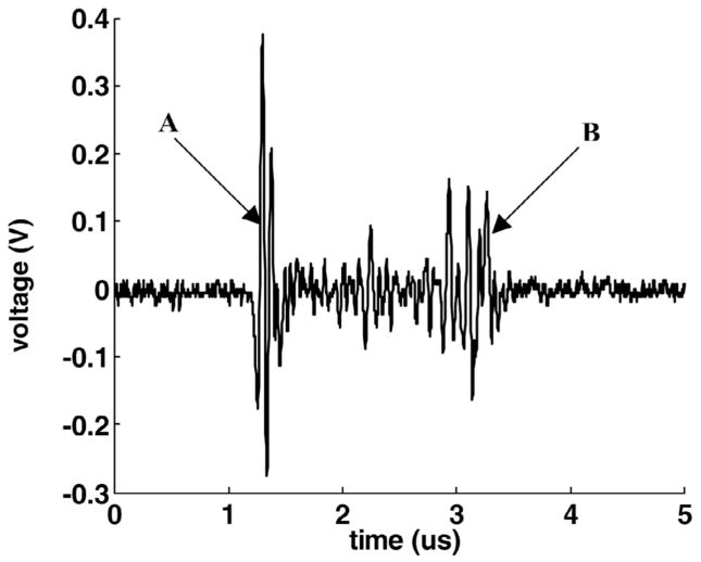
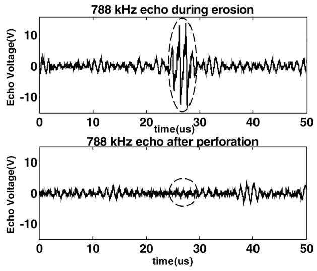
The 20 MHz transducer was used to measure the thickness of the target tissue. The tissue was positioned approximately 2 cm in front the 20-MHz transducer prior to the CUTE process. The transducer was pulsed, and the tissue echo was monitored (Fig. 2). The 20-MHz transducer also functioned as a monitor of tissue perforation. During the CUTE process, it worked as a passive receiver of the 788-kHz pulse echoes. When the tissue was eroded through, there was a sudden decrease in the amplitude of the 788-kHz echo (Fig. 3).
Fig. 2.
An example of the measurement of the tissue thickness. The 20-MHz transducer was pulsed and the echo received from the target tissue. Echo A was from the front surface of the tissue and echo B was from the back surface of the tissue. The time from echo A to B was 2.3 μs, resulting in a computed thickness of 1.8 mm. (The speed of sound in porcine cardiac tissue is 1.572 mm/μs at 26°C [26].)
Fig. 3.
An example of using the 788 kHz echo detected by the 20-MHz transducer as a monitor of tissue perforation. Echo A was from the tissue, which disappeared (echo B) as the tissue was eroded through (PD = 3 cycles in the waveform and PRF = 13.9 kHz).
C. Experimental Design
In the in vitro experiments, five to six holes were created in each piece of tissue. The parameters used in the following experiments were randomized. The thickness of the tissue at the focus of the therapy transducer before each hole was generated (Fig. 2), the time to perforate the tissue (Fig. 3), and the size of the hole measured by hand with a ruler were recorded.
The erosion rate is defined as the thickness of tissue divided by the time to perforate it, e.g., using 2 minutes to erode a 1-mm deep hole, the erosion rate is 1 mm/120 s = 8.33 μm/s. The energy efficiency is defined as the thickness of tissue eroded per joule of energy propagated through the erosion zone (μm/J). It is calculated by the equation below:
where Isata is the spatial average temporal average intensity, defined as the temporal average intensity averaged over the beam cross-sectional area in the focal plane as prescribed in [13]. Beam cross-sectional area in the focal plane is defined as the area consisting of all the points in which the pulse intensity integral is greater than 25% of the maximum pulse intensity integral in the focal plane [13].
For studies of the relationship of erosion rate and energy efficiency to pulse repetition frequency (PRF), and erosion rate and energy efficiency to pulse duration (PD), experiments were conducted on 32 samples. The Isppa and gas saturation were kept constant at 9000 W/cm2 and 40–55%, respectively. Multiple pulses were applied, and the PD was set to 3, 6, 12, and 24 cycles in the acoustic waveform output at the function generator (Fig. 4). For each PD, PRF was changed by varying the duty cycle at discrete values between 2% and 25%.
Fig. 4.
The waveform of the therapeutic ultrasound signal with different PDs delivered by the 788-kHz therapy transducer as recorded by a membrane hydrophone. This figure shows the actual acoustic waveforms with complete ring up and down times. The PD used in this paper is defined as the number of cycles in the waveform at the output of the function generator except for the calculation for Isppa. Panels A, B, C, and D are waveforms in the pressure field at the focus with PDs of 3, 6, 12, and 24 cycles, respectively.
For the study of the relationship of erosion rate and energy efficiency to gas content, experiments were conducted on eight samples. The gas saturation was set to 79–85% with the Isppa kept constant at 9000 W/cm2, the PD was fixed at three cycles, and the PRF was changed by varying the duty cycle at discrete values between 2% and 25%. The results were compared with those obtained from experiments with gas saturation of 40–55% at given parameters. The partial pressure of oxygen (PO2) in air was used as our metric for gas saturation and measured with YSI dissolved oxygen instruments (YSI 5000, Yellow Springs, OH).
D. In Vivo Experiment
A preliminary in vivo experiment was conducted on a canine subject to test the feasibility of perforating the atrial septum in vivo. An adult dog weighing 25 kg was anesthetized and prepared for surgery. A ventral sternotomy provided access to the heart, which was exposed and cradled in the opened pericardium. To ensure controlled ultrasound delivery to the heart, a heated, degassed circulating water bolus was coupled to the heart with a thin plastic membrane and ultrasound coupling gel [14]. The same transducer used in the in vitro experiments was used here. The heart was imaged from the epicardial approach using a commercially available ultrasound imaging system (System FiVe, General Electrics, Milwaukee, WI). The atrial septum was carefully scanned by B-mode and Doppler color flow imaging before and after the procedure. Ultrasound delivered with a PD of six cycles, and a PRF of 13.9 kHz was applied to the lower part of the canine atrial septum for approximately 5 minutes.
The procedures described above were reported to and approved by the University Committee on Use and Care of Animals at the University of Michigan prior to the experiment.
III. Results
A total of 232 of 238 1 to 4-mm diameter, oval-shaped or often round holes generated in forty 1 to 3-mm thick porcine atrial wall samples were included in the following analysis. The results from the other six holes were not considered because the monitoring failed to precisely record the perforation times.
Well-defined holes can be precisely located in porcine atrial wall by therapeutic ultrasound (Fig. 5). We found that the time to perforate the tissue is approximately proportional to the thickness of the tissue using the same set of acoustic parameters. This finding suggested that the tissue might be eroded away at a relatively constant erosion rate. However, the erosion rate observed is only interpretable as the average rate, and so is the energy efficiency.
Fig. 5.
A well-defined hole was created in the porcine atrial wall with a PD of 3 cycles and a PRF of 19.6 kHz.
A. The Effect of PRF on Erosion Rate and Energy Efficiency
1. Erosion Rate and PRF
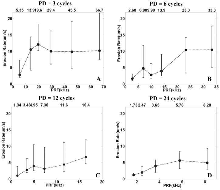
For each PD and PRF, eight holes were generated with a constant Isppa of 9000 W/cm2 and gas saturation of 40–55%. Because the Isppa is constant for each pulse, the energy is proportional to the duty cycle (PRF). However, for PDs of 12 cycles or less, the erosion rate does not increase linearly with energy. Instead for PDs of 3, 6, and 12 cycles, there is a tendency for the erosion to be faster at PRFs of 19.6 kHz, 6.90 kHz, and 4.95 kHz, respectively (Fig. 6). For the 24 cycle PD, the erosion rate increases almost linearly with the PRF.
Fig. 6.
The relationship between the erosion rate and PRF for a fixed PD. In panels A, B, C, and D, the erosion rate was plotted versus PRF by median and range values (min. and max.) for N = 8, corresponding to PDs of 3, 6, 12, and 24 cycles, respectively. In panel A, B, and C, for PDs of 3, 6, and 12 cycles, there is a tendency for the erosion to be faster at PRFs of 19.6 kHz, 6.90 kHz, and 4.95 kHz, respectively. In panel D, for a PD of 24 cycles, the erosion rate increases with the increasing PRF.
Note that, even though the range of values of the erosion rate is higher for shorter PD, the relative values (range of erosion rate/median erosion rate) are comparable (~100%) for all PDs.
2. Energy Efficiency and PRF
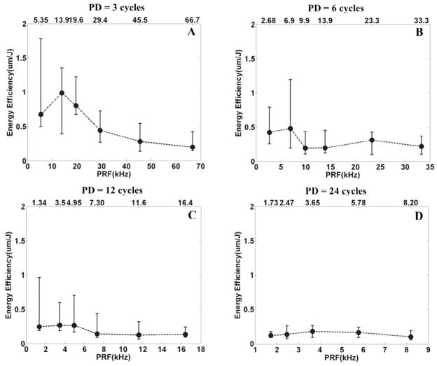
For PDs of 3 and 6 cycles, there are trends of local peaks of energy efficiency at PRFs of 13.9 kHz and 6.90 kHz, respectively (Fig. 7). For PDs of 12 and 24 cycles, local peaks of energy efficiency are not distinct.
Fig. 7.
The relationship between the energy efficiency and PRF for a fixed PD. In panels A, B, C, and D, the energy efficiency was plotted versus PRF by median and range values (min. and max.) for N = 8, corresponding to PDs of 3, 6, 12, and 24 cycles, respectively. In panels A and B, for PDs of 3 and 6 cycles, there are local peaks of energy efficiency at PRFs of 13.9 kHz and 6.90 kHz, respectively. In panels C and D, local peaks of energy efficiency are not distinct.
B. The Effect of PD on Erosion Rate and Energy Efficiency
1. Erosion Rate and PD
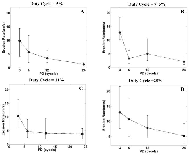
With the same duty cycle (i.e., the same energy), the erosion rate is higher with a shorter PD than a longer PD (Fig. 8). With a 5% duty cycle, the median erosion rate is 10.54 μm/s for a PD of 3 cycles and 1.23 μm/s for a PD of 24 cycles, approximately an 8-fold (p < 0.01; T-test) difference. With a 7.5% duty cycle, the median erosion rate is 12.10 μm/s for a PD of 3 cycles and 2.01 μm/s for a PD of 24 cycles, approximately a 6-fold (p < 0.01; T-test) difference. Note that, at a constant duty cycle, the time average energy is the same for each PD, and the erosion rate is higher with a shorter PD. This suggests the higher energy efficiency with a shorter PD.
Fig. 8.
The relationship between the erosion rate and PD for a fixed duty cycle. In panels A, B, C, and D, the erosion rate was plotted versus PD by median and range values (min. and max.) for N = 8, corresponding to duty cycles of 5%, 7.5%, 11%, and 25%, respectively. In panel A, with a 5% duty cycle, the median erosion rate is 10.54 μm/s for a PD of 3 cycles and 1.23 μm/s for a PD of 24 cycles, approximately an 8-fold difference. In panel B, with a 7.5% duty cycle, the median erosion rate is 12.10 μm/s for a PD of 3 cycles and 2.01 μm/s for a PD of 24 cycles, approximately a 6-fold difference.
2. Energy Efficiency and PD
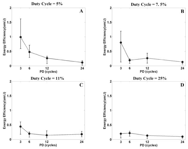
The energy efficiency is higher with a shorter PD (Fig. 9). With a duty cycle of 5%, the median energy efficiency is 0.99 μm/J for a PD of 3 cycles and 0.12 μm/J for a PD of 24 cycles, approximately an 8-fold (p < 0.01; T-test) difference. With a duty cycle of 7.5%, the median energy efficiency is 0.81 μm/J for a PD of 3 cycles and 0.14 μm/J for a PD of 24 cycles, approximately a 6-fold (p < 0.01; T-test) difference. For a lower duty cycle, the average propagated energy is lower, therefore energy efficiency is higher.
Fig. 9.
The relationship between the energy efficiency and PD for a fixed duty cycle. In panels A, B, C, and D, the energy efficiency was plotted versus PD by median and range values (min. and max.) for N = 8, corresponding to duty cycles of 5%, 7.5%, 11%, and 25%, respectively. In panel A, with a duty cycle of 5%, the energy efficiency is 0.99 μm/J for a PD of 3 cycles and 0.12 μm/J for a PD of 24 cycles, approximately an 8-fold difference. In panel B, with a duty cycle of 7.5%, the energy efficiency is 0.81 μm/J for a PD of 3 cycles and 0.14 μm/J for a PD of 24 cycles, approximately a 6-fold difference.
C. The Effect of Gas Saturation on Erosion Rate and Energy Efficiency
1. Erosion Rate and Gas Saturation
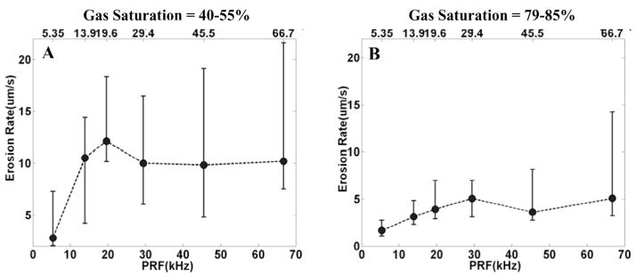
Eight holes were created with 79–85% gas saturation, a PD of 3 cycles, and each PRF between 5.35 kHz and 66.7 kHz (between duty cycle of 2% and 25%). These erosion-rate results were compared with eight holes obtained with a 3-cycle PD and each PRF at 40–55% gas saturation. The erosion rate is greater for the lower gas saturation (Fig. 10). For example, with a PRF of 19.6 kHz, the median erosion rate is 12.10 μm/s for gas saturation of 40–55% and 3.91 μm/s for gas saturation of 79–85%, approximately a 3-fold (p < 0.01; T-test) difference.
Fig. 10.
The relationship between the erosion rate and gas saturation. Panel A is the plot of erosion rate versus PRF, with 40–55% gas saturation and a PD of 3 cycles. Panel B is the plot of erosion rate versus PRF with 79–85% gas saturation and a PD of 3 cycles. The erosion rate was plotted by median and range values (min. and max.) for N = 8. In panel A, the median erosion rate is 12.10 μm/s with a PRF of 19.6 kHz and gas saturation of 40–55%. In panel B, the median erosion rate is 3.91 μm/s with a PRF of 19.6 kHz and gas saturation of 79–85%.
2. Energy Efficiency and Gas Saturation
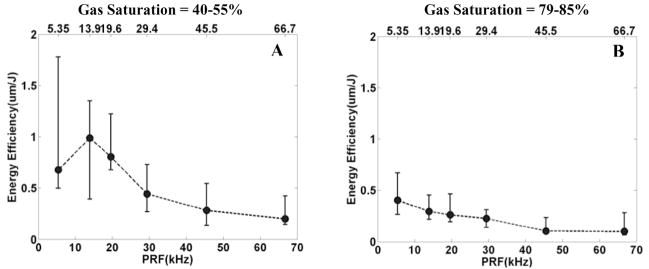
The energy efficiency is greater with lower gas saturation than higher gas saturation (Fig. 11). For example, with a PRF of 13.9 kHz, the median energy efficiency is 0.99 μm/J for gas saturation of 40–55% and 0.30 μm/s for gas saturation of 79–85%, approximately a 3-fold (p < 0.01; T-test) difference.
Fig. 11.
The relationship between the energy efficiency and gas saturation. Panel A is the plot of energy efficiency versus PRF, with 40–55% gas saturation and a PD of 3 cycles. Panel B is the plot of energy efficiency versus PRF with 79–85% gas saturation and a PD of 3 cycles. The energy efficiency was plotted by median and range values (min. and max.) for N = 8. In panel A, the median energy efficiency is 0.99 μm/J with a PRF of 13.9 kHz and gas saturation of 40–55%. In panel B, the median erosion rate is 0.30 μm/s with a PRF of 13.9 kHz and gas saturation of 79–85%.
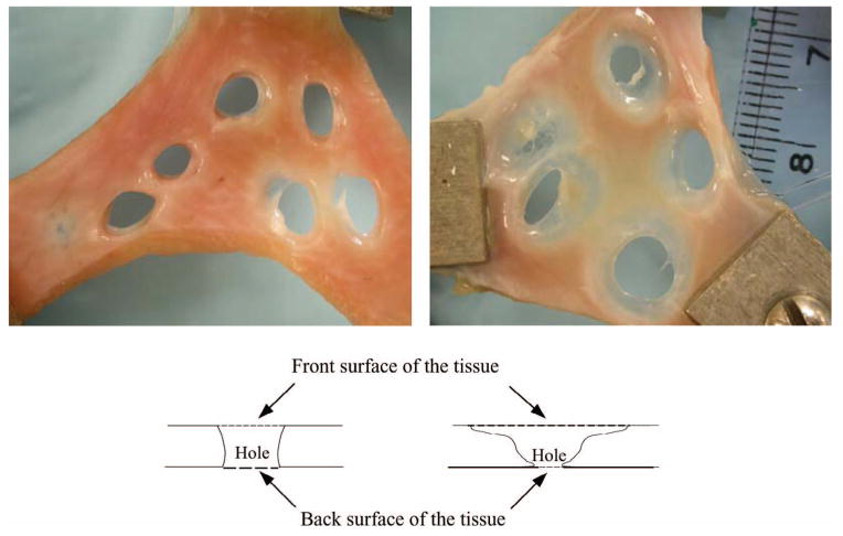
A phenomenon worth noting is that the holes generated with a shorter PD and relatively lower gas saturation have much clearer boundaries than those of the holes generated with a longer PD and relatively higher gas saturation (Fig. 12). The initial appearances of these two samples were comparable.
Fig. 12.
The picture on the left shows holes created with a PD of 3 cycles and 40% gas saturation. The picture on the right depicts the holes created with a PD of 24 cycles and 55% gas saturation. The diagrams depict the formation of the holes corresponding to the pictures above them.
D. In Vivo Experiment
Blood flow between the two atria appeared after multiple ultrasound pulses resulting from the perforation of the atrial septum, shown by the color flow Doppler technique (Fig. 13, panel A). This flow was not present prior to the experiment. The existence of the perforation of the atrial septum also was demonstrated at dissection by inserting a blunt, gauge 18 needle (~1 mm in diameter) through the hole (Fig. 13, panel B). Following the experiment, the heart was fixed in a 10% buffered formalin solution and further dissected for later histologic and microscopic evaluation. In this experiment, the septal movement was along the primary axis of the therapy transducer, so as to minimize its effect on the erosion process. In the future, we plan to use phased arrays to track the septal movement by electronically manipulating the focus.
Fig. 13.
In vivo experiment. Panel A shows the Doppler ultrasound image of the blood flow resulting from the perforation of the atrial septum between the two atria (arrows). Panel B shows the existence of the perforation of the atrial septum by inserting a blunt gauge 18 needle (~1 mm in diameter) through the hole.
IV. Discussion
A working hypothesis, which is consistent with observed results presented herein, is that optimum tissue erosion occurs when the therapeutic ultrasound pulse arrives at the tissue interface when the local bubble population, or the density of cavitation micronuclei, is “just right”. Based on our previous observations [14], [15], a single therapeutic pulse creates a cloud of echogenic microbubbles that decays with time [16], [17]. We have shown that this bubble decay rate may be proportional to the damage produced by a single pulse [15]. A number of potential factors would make the bubble population “just right”, such as limited shadowing, high concentrations of suitable nuclei for inertial cavitation, the proximity of the bubble cloud to the tissue surface, etc. It has been noted in the past that various pulse parameters in ultrasound can produce optimal effects [1], [2], [10], [18]–[22] and that the gas content can affect collapse energy [23], [24].
In the multiple pulse experiments, which are the basis for the tissue erosion phenomenon reported herein, we postulate that each pulse creates a cloud of temporally decaying microbubbles. If the PRF is too high (i.e., a succeeding pulse occurs before this decay has reached the optimum bubble density for effective erosion), the “shadowing” phenomenon occurs where the ultrasound is significantly scattered. This explains a local reduction in erosion efficiency. If the PRF is too low, each pulse essentially acts alone with no synergistic effect provided by residual cavitation nuclei from earlier pulses. This could explain the optimum PRFs seen for the shorter pulse durations. Similar results showing that increasing PRF does not always increase bioeffect have been noted by Smith and Hynynen [10]. For longer pulse durations, the bubble cloud produced by a given pulse could have a longer decay time. Fig. 6 indicates that the overall erosion rate is diminished as the PD is increased. It might be expected that the optimum PRF would be lower as the PD increases in order to allow time for the larger bubble cloud to decay. More work will be required to test this hypothesis.
Our preliminary experiments show that the CUTE technique can perforate soft tissue for all gas saturations, although the process is slower at higher gas saturation. The reduced erosion rates at higher gas saturations also may be the result of too many microbubbles causing shadowing and disappearance of the optimum PRF, along with changing collapse dynamics due to more rapid diffusion of gas.
A corollary to this hypothesis is that most of the tissue damage may occur during the first several cycles of the therapeutic waveform, producing diminishing results for each additional cycle. This is certainly seen in our results in which longer pulses are less efficient at eroding tissue. This has significance for treatment planning wherein reduction in the total propagated energy to produce a desired effect is critical, particularly when trying to avoid thermal damage to overlying tissues. This is a significant problem when large volumes are being treated [25]. The results presented here suggest ways to produce desired effects with minimal propagated energy, the goal motivating much of our recent research.
Direct experiments to test the hypotheses outlined above are currently underway and should allow us to more precisely understand the underlying phenomena associated with controlled ultrasonic tissue erosion, or histotripsy. Only then can optimization of exposure parameters proceed on a rational basis.
V. Conclusions
We show that well-defined perforations can be precisely located in porcine atrial wall by therapeutic ultrasound. A high erosion rate and energy efficiency can be achieved by optimizing exposure parameters (e.g., PRF, PD, and gas saturation). The just right hypothesis, which is consistent with our results, may provide a theoretical basis of the CUTE process. This process may be developed as a potentially effective noninvasive tool in the treatment of intact atrial septum in neonatal patients with HLHS, as well as many other clinical procedures in which mechanical subdivision and removal of soft tissue would be indicated.
Acknowledgments
This research has been funded by grants from the National Institutes of Health RR14450.
The authors thank Dr. Oliver Kripfgans for his tremendous help with the calibration procedure. We also thank Dr. Kimberly Ives for her assistance with the animal experiments and Dr. Gerald Abram for his support for the histological evaluation.
Biographies

Zhen Xu was born in Nanjing, China, in 1979. She received the B.S.E. (highest honors) degree from Southeast University, Nanjing, China, in 2001, and the M.S. degree from the University of Michigan, Ann Arbor, MI in 2003, both in Biomedical Engineering. She is currently a Ph.D. candidate in Biomedical Engineering at the University of Michigan. Her research is focusing on ultrasound therapy, particularly the applications of high-intensity ultrasound for noninvasive surgeries. She was awarded three Departmental fellowships of Biomedical Engineering from Southeast University from 1997 to 2000 and a Departmental fellowship of Biomedical Engineering from the University of Michigan in 2001.
Achi Ludomirsky, M.D., is The Louis Larrick Ward Professor of Pediatrics and Biomedical Engineering at Washington University in St. Louis. He received his M.D. degree Magnum Cum Laude in 1977 from the Sackler Medical School at the University of Tel-Aviv, Israel. He completed his pediatric residency at Hadassah University Hospital in Jerusalem, Israel and his Pediatric Cardiology Fellowship at Baylor College of Medicine from 1984 to 1987. From 1987 to 1992, he was the Director of Echocardiographic Research at Texas Children’s Hospital, Baylor College of Medicine in Houston, Texas. From 1992 until 2003, he was the Director of the Echocardiography Laboratory at the University of Michigan, Ann Arbor, Michigan. In August of 2003, he became the Chief and Director of the Division of Pediatric Cardiology at the Edward Mallinckrodt Department of Pediatrics at St. Louis Children’s Hospital/Washington University School of Medicine, St. Louis. In September of 2003, he was named the Louis Larrick Ward Professor of Pediatrics and Biomedical Engineering.
Dr. Ludomirsky has been involved in numerous clinical research projects in the field of pediatric cardiology, especially in different imaging modalities. He published extensively in the area of clinical ultrasound and in 1998, joined the biomedical engineering team at the University of Michigan in the development of the use of high intensity focal ultrasound for clinical application. Dr. Ludomirsky is a fellow of the American College of Cardiology and the American Heart Association and also served as the Chairman of the Pediatric Chapter of the American Society of Echo. He is currently Director of the Board of the American Society of Echocardiography. He was a member of the Technology Transfer Committee at the University of Michigan and he has continued to develop and enhance his relation between industry and the medical experts.

Lucy Eun, M.D., is a visiting lecturer and research scholar in department of Pediatrics Cardiology at University of Michigan in Ann Arbor since August 2001. She received her M.D. degree in 1993 from Yonsei University College of Medicine, Seoul, Korea. She completed her pediatric residency at Yonsei University College of Medicine, Seoul, Korea and her Pediatric Cardiology Fellowship at Yonsei University College of Medicine, Seoul, Korea from 1998 to 2000.
She has been involved in numerous clinical research projects in the field of pediatric cardiology, especially in echocardiographic imaging modalities. She has been interested specifically in the area of tissue Doppler imaging in echocardiographic field, and involved in the biomedical engineering team at the University of Michigan in the development of the use of high intensity focal ultrasound for clinical application.
Tim L. Hall (S’98) was born in Lansing, MI in 1975. He received the B.S.E. degree in 1998 and M.S.E. degree in 2001, both in Electrical Engineering from the University of Michigan, Ann Arbor, MI. From 1998–1999, he worked at Teradyne Inc., Boston, MA, as a design engineer. He is currently a visiting research investigator with the Department of Biomedical Engineering, the University of Michigan, developing miniature driving systems for high power, multi-element phased array transducers for ultrasound therapy. His research interests include designing and developing ultrasound therapy systems and applications.

Binh C. Tran (S’99) was born in Saigon, Vietnam on July 9, 1976. He received the B.S.E. degree in Electrical Engineering in 1998 and the M.S. degree in Biomedical Engineering in 2000, both from the University of Michigan, Ann Arbor, MI. He is currently a Ph.D. candidate in Biomedical Engineering at the University of Michigan. His research interests are high intensity ultrasound for non-invasive surgery and microbubble enhanced ultrasound therapies. He was awarded a Whitaker Foundation fellowship in 1999.
Jeffery Brian Fowlkes (M’94–A’94) is an Associate Professor in the Department of Radiology and Associate Professor in the Department of Biomedical Engineering. He is currently directing and conducting research in medical ultrasound including the use of gas bubbles for diagnostic and therapeutic applications. His work includes studies of ultrasound contrast agents for monitoring tissue perfusion, acoustic droplet vaporization for bubble production in cancer therapy and phase aberration correction, and effects of gas bubbles in the use of high intensity ultrasound. Dr. Fowlkes received his B.S. degree in physics from the University of Central Arkansas in 1983, and his M.S. and Ph.D. degrees from the University of Mississippi in 1986 and 1988, respectively, both in physics.
Contributions to the scientific community by Dr. Fowlkes include educational and research efforts and organizational service. Dr. Fowlkes has served the medical ultrasonic community by his participation in the American Institute of Ultrasound in Medicine as a member of its Board of Governors, as the Chair of its Bioeffects Committee, as a member of its Technical Standards and Annual Convention Committees. He also received the AIUM Presidential Recognition Award for outstanding contributions and service to the expanding future of ultrasound in medicine. As a member of the Acoustical Society of America, Dr. Fowlkes has served on the Physical Acoustics Technical Committee and the Medical Acoustics and Bioresponse to Vibration Technical Committee and on a standards committee working group on cavitation detection and monitoring. As a Member of the IEEE, he has worked with the IEEE I&M Society Technical Committee on Imaging Systems.

Charles A. Cain (S’65–M’71–SM’80–F’89) was born in Tampa, FL, on March 3, 1943. He received the B.E.E. (highest honors) degree in 1965 from the University of Florida, Gainesville, FL; the M.S.E.E. degree in 1966 from the Massachusetts Institute of Technology, Cambridge, MA; and the Ph.D. degree in electrical engineering in 1972 from the University of Michigan, Ann Arbor, MI.
During 1965–1968, he was a member of the Technical Staff at Bell Laboratories, Naperville, IL, where he worked in the electronic switching systems development area. During 1972–1989, he was in the Department of Electrical and Computer Engineering at the University of Illinois at Urbana-Champaign, where he was a Professor of Electrical Engineering and Bioengineering. Since 1989, he has been in the College of Engineering at the University of Michigan, Ann Arbor, as a Professor of Biomedical Engineering and of Electrical Engineering. He was the Chair of the Biomedical Engineering Program from 1989 to 1996; the Founding Chair of the Biomedical Engineering Department from 1996–1999; and was named the Richard A. Auhll Professor of Engineering in 2002.
He has been involved in research on the medical applications of ultrasound, particularly high intensity ultrasound for non-invasive surgery. He was formerly an Associate Editor of the IEEE Transactions on Biomedical Engineering and the IEEE Transactions on Ultrasonics, Ferroelectrics, and Frequency Control; and an editorial board member of the International Journal of Hyperthermia and Radiation Research. He is a Fellow of the IEEE and the AIMBE.
References
- 1.Henglein A, Gutierrez M. Chemical reactions by pulsed ultrasound: Memory effects in the formation of NO3- and NO2-in aerated water. Int J Radiat Biol Related Studies Phys Chem Med. 1986;50:527–533. doi: 10.1080/09553008614550921. [DOI] [PubMed] [Google Scholar]
- 2.Child SZ, Hartman CL, Schery LA, Carstensen EL. Lung damage from exposure to pulsed ultrasound. Ultrasound Med Biol. 1990;16:817–825. doi: 10.1016/0301-5629(90)90046-f. [DOI] [PubMed] [Google Scholar]
- 3.Frizzell LA, Chen E, Lee C. Effects of pulsed ultrasound on the mouse neonate: Hind limb paralysis and lung hemorrhage. Ultrasound Med Biol. 1994;20:53–63. doi: 10.1016/0301-5629(94)90017-5. [DOI] [PubMed] [Google Scholar]
- 4.Dalecki D, Raeman CH, Child SZ, Carstensen EL. Intestinal hemorrhage from exposure to pulsed ultrasound. Ultrasound Med Biol. 1995;21:1067–1072. doi: 10.1016/0301-5629(95)00041-o. [DOI] [PubMed] [Google Scholar]
- 5.El-Bialy TH, Royston TJ, Magin RL, Evans CA, Zaki Ael M, Frizzell LA. The effect of pulsed ultrasound on mandibular distraction. Ann Biomed Eng. 2002;30:1251–1261. doi: 10.1114/1.1529196. [DOI] [PubMed] [Google Scholar]
- 6.Li JK, Chang WH, Lin JC, Ruaan RC, Liu HC, Sun JS. Cytokine release from osteoblasts in response to ultrasound stimulation. Biomaterials. 2003;24:2379–2385. doi: 10.1016/s0142-9612(03)00033-4. [DOI] [PubMed] [Google Scholar]
- 7.Naruse K, Miyauchi A, Itoman M, Mikuni-Takagaki Y. Distinct anabolic response of osteoblast to low-intensity pulsed ultrasound. J Bone Miner Res. 2003;18:360–369. doi: 10.1359/jbmr.2003.18.2.360. [DOI] [PubMed] [Google Scholar]
- 8.Warden S. A new direction for ultrasound therapy in sports medicine. Sports Med. 2003;33:95–107. doi: 10.2165/00007256-200333020-00002. [DOI] [PubMed] [Google Scholar]
- 9.Pfaffenberger S, Devcic-Kuhar B, El-Rabadi K, Groschl M, Speid WS, Weiss TW, Huber K, Benes E, Maurer G, Wojta J, Gottsauner-Wolf M. 2MHz ultrasound enhances t-PA-mediated thrombolysis: Comparison of continuous versus pulsed ultrasound and standing versus travelling acoustic waves. Thrombosis Haemostasis. 2003;89:583–589. [PubMed] [Google Scholar]
- 10.Smith NB, Hynynen K. The feasibility of using focused ultrasound for transmyocardial revascularization. Ultrasound Med Biol. 1998;24:1045–1054. doi: 10.1016/s0301-5629(98)00086-6. [DOI] [PubMed] [Google Scholar]
- 11.Brayman AA, Lizotte LM, Miller MW. Erosion of artificial endothelia in vitro by pulsed ultrasound: Acoustic pressure, frequency, membrane orientation and microbubble contrast agent dependence. Ultrasound Med Biol. 1999;25:1305–1320. doi: 10.1016/s0301-5629(99)00076-9. [DOI] [PubMed] [Google Scholar]
- 12.Coleman AJ, Saunders JE. A review of the physical properties and biological effects of the high amplitude acoustic field used in extracorporeal lithotripsy. Ultrasonics. 1993;31:75–89. doi: 10.1016/0041-624x(93)90037-z. [DOI] [PubMed] [Google Scholar]
- 13.Acoustic Output Measurement Standard for Diagnostic Ultrasound Equipment: AIUM/NEMA, May 1998.
- 14.Tran BC, Seo J, Fowlkes JB, Cain CA. Microbubble enhanced cavitation for non-invasive ultrasound surgery. Proc. IEEE Ultrason. Symp; to be published. [DOI] [PubMed] [Google Scholar]
- 15.Seo J, Tran BC, Fowlkes JB, Cain CA. Evaluation of ultrasound surgery based on changes in images echogenicity. Proc. IEEE Ultrason. Symp.; to be published. [Google Scholar]
- 16.Flynn HG, Church CC. A mechanism for the generation of cavitation maxima by pulsed ultrasound. J Acoust Soc Amer. 1984;76:505–512. doi: 10.1121/1.391592. [DOI] [PubMed] [Google Scholar]
- 17.Huber P, Debus J, Jochle K, Simiantonakis I, Jenne J, Rastert R, Spoo J, Lorenz WJ, Wannenmacher M. Control of cavitation activity by different shockwave pulsing regimes. Phys Med Biol. 1999;44:1427–1437. doi: 10.1088/0031-9155/44/6/301. [DOI] [PubMed] [Google Scholar]
- 18.Fowlkes JB, Crum LA. Cavitation threshold measurements for microsecond length pulses of ultrasound. J Acoust Soc Amer. 1988;83:2190–2201. doi: 10.1121/1.396347. [DOI] [PubMed] [Google Scholar]
- 19.Atchley AA, Frizzell LA, Apfel RE, Holland CK, Madanshetty S, Roy RA. Thresholds for cavitation produced in water by pulsed ultrasound. Ultrasonics. 1988;26:280–285. doi: 10.1016/0041-624x(88)90018-2. [DOI] [PubMed] [Google Scholar]
- 20.Holland CK, Apfel RE. Thresholds for transient cavitation produced by pulsed ultrasound in a controlled nuclei environment. J Acoust Soc Amer. 1990;88:2059–2069. doi: 10.1121/1.400102. [DOI] [PubMed] [Google Scholar]
- 21.Chang PP, Chen WS, Mourad PD, Poliachik SL, Crum LA. Thresholds for inertial cavitation in albunex suspensions under pulsed ultrasound conditions. IEEE Trans Ultrason, Ferroelect, Freq Contr. 2001;48:161–170. doi: 10.1109/58.895927. [DOI] [PubMed] [Google Scholar]
- 22.Ciaravino V, Flynn HG, Miller MW. Pulsed enhancement of acoustic cavitation: A postulated model. Ultrasound Med Biol. 1981;7:159–166. doi: 10.1016/0301-5629(81)90005-3. [DOI] [PubMed] [Google Scholar]
- 23.Leighton TG. The Acoustic Bubble. San Diego: Academic; 1994. p. 335. [Google Scholar]
- 24.Tuziuti T, Hatanaka S, Yasui K, Kozuka T, Mitome H. Influence of dissolved oxygen content on multibubble sonoluminescence with ambient-pressure reduction. Ultrasonics. 2002;40:651–654. doi: 10.1016/s0041-624x(02)00192-0. [DOI] [PubMed] [Google Scholar]
- 25.Wan H, Aarsvold J, O’Donnell M, Cain CA. Thermal dose optimization for ultrasound tissue ablation. IEEE Trans Ultrason, Ferroelect, Freq Contr. 1999;46:913–928. doi: 10.1109/58.775658. [DOI] [PubMed] [Google Scholar]
- 26.Duck FA. Physical Properties of Tissue. New York: Academic; 1990. [Google Scholar]


