Abstract
A systematic experimental study and theoretical modeling of the device physics of polydimethylsiloxane “pushdown” microfluidic valves are presented. The phase space is charted by 1587 dimension combinations and encompasses 45-295 μm lateral dimensions, 16-39 μm membrane thickness, and 1-28 psi closing pressure. Three linear models are developed and tested against the empirical data, and then combined into a fourth-power-polynomial superposition. The experimentally validated final model offers a useful quantitative prediction for a valve's properties as a function of its dimensions. Typical valves (80-150 μm width) are shown to behave like thin springs.
INTRODUCTION
Within a decade, polymethylsiloxane (PDMS) microfluidics has negotiated the long distance from the plain channel1 to a plethora of specialized components organized by the thousands in large-scale-integration devices,2 thereby fulfilling Feynman's dreams of infinitesimal machines3,4 at least at the microscale. The now mature technology has been successfully used in a number of important applications, e.g., protein crystallization,5 DNA sequencing,6 nanoliter polymerase chain reaction (PCR),7 cell sorting and cytometry,8 nucleic acid extraction and purification,9 immunoassays,10 and cell studies.11
However, PDMS microfluidics has developed so vigorously that the drive to build specific applications has overshadowed systematic exploration of the underlying technology.12 The generated gaps in the body of knowledge have only recently started being addressed.13 Herein, we take the systematic approach towards the mechanical behavior of a fundamental microfluidic component—the pushdown valve.14
EXPERIMENTAL PROCEDURES
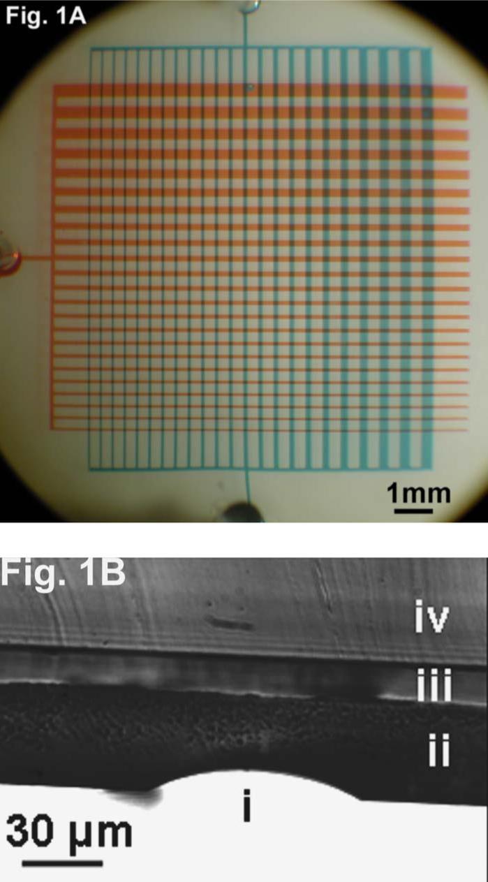
Standard techniques and reagents10 were used in the fabrication of the microfluidic devices of the following architecture. A comblike array of parallel channels in one PDMS layer orthogonally crossed a similar array in the other layer to produce a pushdown valve at each intersection in the matrix [Fig. 1(a)]. The valve lengths L and widths W varied between 45 and 295 μm, while the flow channel height was fixed at H=10±0.5 μm. Groups of devices were fabricated at PDMS spin speeds of 1500, 2000, and 2500 rpm, producing valve membrane thicknesses h=39, 26, and 16 (±0.5) μm, respectively [Fig. 1(b)].
FIG. 1.

(Color online) Microfluidic chip. (A) Control/flow channels are filled with red/blue dye, respectively, and form a microfluidic valve at each intersection. (B) After the closing pressures of all valves are measured, the device is peeled off the glass substrate and cut along a line perpendicular to the flow channels. Membrane dimensions are measured using a calibrated eyepiece reticle. In the shown example, a 2000 rpm device was cut along one of the control channels. The valve arch (i), flow layer (ii), control channel (iii), and control layer (iv) are clearly visible.
A typical microfluidic testing station was used to obtain the experimental data.10 Control lines were filled with water by applying pressure and letting the air escape through the elastomeric matrix. Then pressure was increased monotonically in steps of 0.5±0.05 psi, starting from 0 psi above atmospheric pressure. After each increase, the matrix was scanned on the microscope to identify the valves that were currently closed but had been still open at the previous pressure setting. Closing pressures were thus identified for each of 1587 dimension combinations.
RESULTS
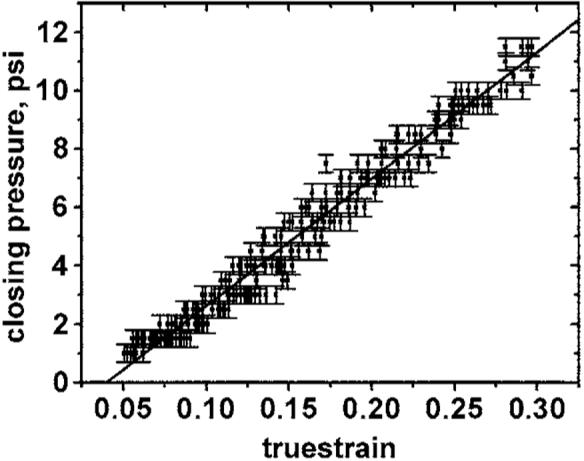
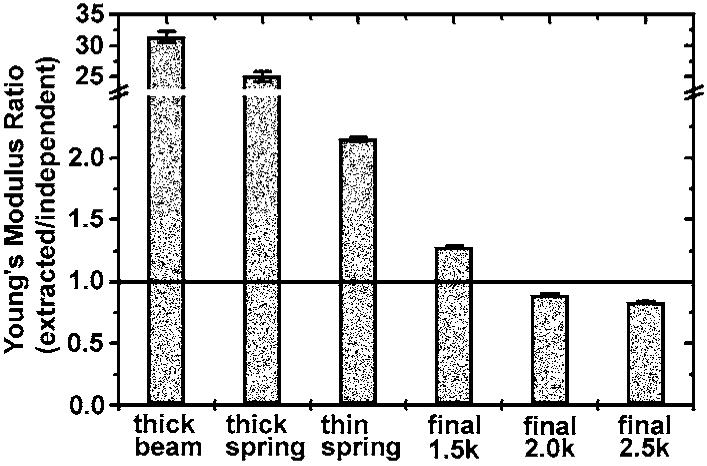
Several linear models were developed. The strain expression for each model was combined with the experimental data to produce stress-strain plots (e.g., Fig. 2). Values for Young's modulus were extracted from linear fits (Fig. 2) and compared (Fig. 3) to the value from the literature15 (0.36 MPa) to judge the validity of the model.
FIG. 2.

Stress-strain scatter plots and fits. Closing pressures are plotted vs the true strains calculated by each model. Linear fits of the lower strain regions yield values for Young's modulus of PDMS. Shown is the result for 2500 rpm under the final linear superposition model.
FIG. 3.

Models. Comparison of an independently measured value (Ref. 15) of Young's modulus with those extracted by each model determines the quality of the model. The linear superposition of all models produces the best agreement and offers a quantitative prediction of the properties of microfluidic valves over a large dynamic range of critical parameters. The dominant linear behavior is one of a thin spring.
The thick beam
At least for some of the devices in the explored phase space, the vertical and lateral dimensions of the valve slabs are quite comparable (e.g., H×W×L=39×50×60 μm3), while for others there is a great disparity between the two lateral dimensions (e.g., H×W×L=39×45×295 μm3). Thus, it makes sense to have a “thick beam” model to help account for the corresponding behavior. A thick beam is described16 by
| (1) |
where z is the deflection of the beam end with respect to the nondeformed state, F is the force applied to that end, L is the length of the beam, E is Young's modulus of the material, and I is the moment of inertia of a unit mass per unit area,
| (2) |
where y is the coordinate perpendicular to both the bending axis and the beam axis, while A is the cross-section area of the beam.
If the valve is viewed as two joined thick beams,16 then z=H and L=W/2. Also, the total force on the valve from applied pressure P must be
to balance a closed valve. Using dA=dxdy, Eq. (2) is integrated to yield
Plugging everything back into Eq. (1) obtains
| (3) |
However, the bending of the membrane is not really two dimensional (2D) but three dimensional (3D) and into the shape of a saddle, whereby a transverse contraction is combined with a longitudinal extension. Equation (3) takes only the former in the account. The latter is analogously modeled producing a formula wherein W is replaced with L. Superposition yields
| (4) |
Since H,h<W,L for our experimental values, this model produces small strains and thus large E (≈11 MPa, Fig. 3). Hence in the final model we would need additional terms of lower powers of (h,H)/(W,L). Physically, the strain contribution from thick beam bending is too small to account for the entire stress.
The thin spring
The valve membrane can be viewed as a one-dimensional (1D) spring that is contracted as the valve closes. In this case, vertical pressure must be connected with horizontal stress. To do so, perhaps the valve can be treated as a semiliquid slab. After all, an elastomer does not have a strongly cross-linked matrix, the rotational energy along the Si-O bond in PDMS is zero, and most chains are free to slide past one another inside the material. As a result, just as in liquids, the static pressure on the surface must be equalized by pressure inside the volume (otherwise, the situation would not be static). Then the outside pressure and stress inside the material must be equal, while stress and strain are constant through slab's volume. Hence,
| (5) |
The strain is the percentile change in length of the spring, or the difference of flow channel arch length and W, divided by W,
| (6) |
Approximating the arch as a parabola yields
Plugging this back into Eq. (6) then plugging the result into Eq. (5) obtains
| (7) |
The above only takes into account the transverse contraction but not the longitudinal extension. The latter is analogously modeled producing a formula wherein W is replaced with L. Superposition yields
| (8) |
This model produces values for E(≈2 MPa) still exceeding the correct value (Fig. 3). In addition, this model lacks any dependence on h, because the one-dimensional spring has no thickness. If N identical springs are arranged in parallel, they will act as a spring of N times larger constant, or a spring that is N times thicker. Therefore, the final strain expression must contain a term that is linear in h, necessitating a thick spring model.
The thick spring
The valve membrane can be viewed as a suspension bridge across the flow channel, wherein the force due to the applied pressure,
is canceled by the vertical projections of forces F2 along the cable,
where
The cross-section area of the spring is hL, while the stress is the same everywhere, and so we can rewrite Eq. (5) as
Combining all of the above obtains
Plugging in the strain from Eq. (7) and dropping the sixth power terms (since h, H<W, L) yield
Applying the same reasoning in the longitudinal direction produces an analogous expression where W is replaced with L. Superposition yields
| (9) |
This model boasts the needed first power in h but still overestimates E if used alone (Fig. 3). It is clear that all models have to be combined to produce the final model.
The final picture
We can now superpose all three models. In addition, the pressure is not equal to the “engineering” stress but to the “true” stress. To write the equation for the pressure we thus have to use the true strain,
Now we are ready to write the final functional form,
| (10) |
This final model (Fig. 2) produces the best agreement (Fig. 3) with the independently measured value15 and offers a good quantitative prediction, especially in the typically used regime of thin wide membranes and low strains.
DISCUSSION
From the physics perspective, it is illuminating that among the three basic linear models, the thin spring is by far closest to reality. That tells us that for the most typical dimensions, the valves do act approximately like thin springs. On the other hand, the need for the inclusion of other basic models is dictated by extreme conditions, namely, thickest membranes and smallest widths, where the volume effects become more prominent.
The final linear model presents a useful practical approximation for most applications in the field. However, it is clear that further improvements in the accuracy of predictions would require the development of nonlinear models, especially for very large strains where the stress-strain curve significantly departs from the initial linear regime. We would be happy to share our detailed experimental data with workers willing to undertake that endeavor.
The experimental part of the work also revealed interesting information about the occurrence of device failure. The only observed such was due to the valve membrane being so flabby that it would get stuck to the substrate and become bound to it during the fabrication process, producing a nonfunctional valve. This is a well-known phenomenon and was observed in our study to become frequent when both lateral dimensions exceeded 115 and 130 μm for 2500 and 2000 rpm, respectively. No such collapse was observed with the 1500 rpm devices, probably because the corresponding membrane is significantly thicker while the maximal lateral dimensions were limited to 300 μm.
CONCLUSIONS
A systematic study of the mechanical properties of PDMS microfluidic valves is presented. Three linear models are developed and tested against the empirical data, and then superposed into the final model, which offers a useful quantitative prediction for the valve properties as a function of its dimensions. The dominant linear behavior of valve membranes typically used in the field is shown to be one of thin springs.
ACKNOWLEDGMENTS
The authors thank Alejandro Meruelo and Daniel O'Hanlon from Caltech for their help with preliminary steps, and Alejandra Torres, Christina Morales, and Ali Ghaffari of the Caltech Micro/Nano-Fluidic Foundry for their help with device fabrication. Financial support for this work was provided by the NIH 1RO1 HG002644-01A1 and NIH 1 K99EB007151-01.
References
- 1.Duffy DC, McDonald JC, Schueller OJA, Whitesides GM. Anal. Chem. 1998;70:4974. doi: 10.1021/ac980656z. [DOI] [PubMed] [Google Scholar]
- 2.Thorsen T, Maerkl SJ, Quake SR. Science. 2002;298:580. doi: 10.1126/science.1076996. [DOI] [PubMed] [Google Scholar]
- 3.Feynman RF. J. Microelectromech. Syst. 1992;1:60. [Google Scholar]
- 4.Feynman RF. J. Microelectromech. Syst. 1993;2:4. [Google Scholar]
- 5.Hansen CL, Skordalakes E, Berger JM, Quake SR. Proc. Natl. Acad. Sci. U.S.A. 2002;99:16531. doi: 10.1073/pnas.262485199. [DOI] [PMC free article] [PubMed] [Google Scholar]
- 6.Kartalov EP, Quake SR. Nucleic Acids Res. 2004;32:2873. doi: 10.1093/nar/gkh613. [DOI] [PMC free article] [PubMed] [Google Scholar]
- 7.Liu J, Hansen C, Quake SR. Anal. Chem. 2003;75:4718. doi: 10.1021/ac0346407. [DOI] [PubMed] [Google Scholar]
- 8.Fu AY, Chou H-P, Spence C, Arnold FH, Quake SR. Anal. Chem. 2002;74:2451. doi: 10.1021/ac0255330. [DOI] [PubMed] [Google Scholar]
- 9.Hong JH, Studer V, Hang G, Anderson WF, Quake SR. Nat. Biotechnol. 2004;22:435. doi: 10.1038/nbt951. [DOI] [PubMed] [Google Scholar]
- 10.Kartalov EP, Zhong JF, Scherer A, Quake SR, Taylor CR, Anderson WF. BioTechniques. 2006;40:85. doi: 10.2144/000112071. [DOI] [PubMed] [Google Scholar]
- 11.Balagadde FK, You L, Hansen CL, Arnold FH, Quake SR. Science. 2005;309:137. doi: 10.1126/science.1109173. [DOI] [PubMed] [Google Scholar]
- 12.Kartalov EP, Scherer A, Anderson WF. J. Nanosci. Nanotechnol. 2006;6:2265. doi: 10.1166/jnn.2006.504. [DOI] [PubMed] [Google Scholar]
- 13.Goulpeau J, Trouchet D, Ajdari A, Tabeling P. J. Appl. Phys. 2005;98:044914. [Google Scholar]
- 14.Unger MA, Chou H-P, Thorsen T, Scherer A, Quake SR. Science. 2000;288:113. doi: 10.1126/science.288.5463.113. [DOI] [PubMed] [Google Scholar]
- 15.Armani D, Liu C, Aluru N. Re-configurable fluid circuits by PDMS elastomer micromachining. Proceedings of IEEE Micro Electro Mechanical System (MEMS) '99; Orlando, FL. 17-21 January 1999; Piscataway, NJ: IEEE; pp. 222–227. [Google Scholar]
- 16.Feynman RP, Leighton RB, Sands M. The Feynman Lectures on Physics. Vol. II. Addison-Wesley; Reading, MA: 1963. Chap. 38. [Google Scholar]


