Abstract
Helical scanning configuration has been used widely in diagnostic cone-beam computed tomography (CBCT) for acquiring data sufficient for exact image reconstruction over an extended volume. In image-guided radiation therapy (IGRT) and other applications of CBCT, it can be difficult, if not impossible, to implement mechanically a multiple-turn helical trajectory on the imaging systems due to hardware constraints. However, imaging systems in these applications often allow for the implementation of a reverse helical trajectory in which the rotation direction changes between two consecutive turns. Because the reverse helical trajectory satisfies Tuy’s condition, when projections of the imaged object are nontruncated, it yields data sufficient for exact image reconstruction within the reverse helix volume. The recently developed chord-based algorithms such as the backprojection filtration (BPF) algorithm can readily be applied to reconstructing images on chords of a reverse helical trajectory, and they can thus reconstruct an image within a volume covered by the chords. Conversely, the chord-based algorithms cannot reconstruct images within regions that are not intersected by chords. In a reverse helix volume, as shown below, chordless regions exist in which no images can thus be reconstructed by use of the chord-based algorithms. In this work, based upon Pack–Noo’s formula, a shift-invariant filtered backprojection (FBP) algorithm is derived for exact image reconstruction within the reverse helix volume, including the chordless region. Numerical studies have also been conducted to demonstrate the chordless region in a reverse helix volume and to validate the FBP algorithm for image reconstruction within the chordless region. Results of the numerical studies confirm that the FBP algorithm can exactly reconstruct an image within the entire reverse helix volume, including the chordless region. It is relatively straightforward to extend the FBP algorithm to reconstruct images for general trajectories, including reverse helical trajectories with variable pitch, tilted axis, and∕or additional segments between turns.
Keywords: cone-beam computed tomography, reconstruction, reverse helical, filtered backprojection, image-guided radiation therapy
INTRODUCTION
Computed tomography (CT) is used widely as one of the leading imaging modalities in image-guided radiation therapy (IGRT). In the last few years, cone-beam CT (CBCT) with a KV source that is mounted on the rotation gantry of a linear accelerator (LINAC) treatment system has become commercially available.1, 2, 3 Integration of such a KV-CT imaging component into the LINAC system allows the KV-imaging and MV-treatment processes to share identical spatial, and temporal information about the treated patient. Currently, a KV-CT imaging scanner mounted on LINAC treatment system acquires cone-beam data by use of a scanning configuration in which the x-ray source and the detector move along a circular trajectory, largely because the mechanical implementation of a circular configuration is relatively easy. The FDK algorithm4 and its variations have been proposed, and widely used in practice, for reconstructing approximate images from circular cone-beam data. However, due to data insufficiency, there may exist cone-beam image artifacts that include intensity drop, streak artifacts, and image deformation in reconstructed images.5, 6 The image artifacts would become more serious when a larger cone angle is used for acquiring data.
The helical source trajectory has become a standard scanning configuration in diagnostic CT because it can collect cone-beam data sufficient for exact reconstruction of volume images. Diagnostic CT achieves an extended longitudinal coverage by use of the slip-ring technology, which allows the x-ray source and the detector to rotate multiple turns continuously in one direction, while the patient couch is translated at a constant speed along one direction, thus forming a multiple-turn helical source trajectory. The LINAC-mounted KV cone-beam CT, however, can rotate only one turn in either direction, and must reverse rotation direction after each turn. Therefore, the LINAC-mounted KV cone-beam CT imager can achieve only a one-turn helical source trajectory without altering the couch motion mode. It is expected that certain image-guided radiation therapy (IGRT) applications based on cone-beam CT images may benefit from an extended volume coverage of the patient.7 Although single-turn helical trajectory offers some extension of the imaged volume, it may be desirable to achieve an extended longitudinal coverage beyond that of a one-turn helical trajectory. One natural way to extend the longitudinal coverage is that the couch is translated continuously along one direction while the LINAC gantry reverses its rotation direction after each turn, thus resulting in a multiple-turn reverse helical trajectory.
In this work, we investigate image reconstruction from cone-beam data acquired with reverse helical trajectories. In the last several years, significant advances have been made in algorithm development for accurate image reconstruction in helical CBCT, including Katsevich’s filtered-backprojection-type algorithm and the chord-based algorithms.8, 9, 10 These algorithms have also been extended to the algorithms for general source trajectories.11, 12, 13, 14, 15 We first apply, in this work, the recently developed chord-based algorithm10, 13 to reconstructing images because they are directly applicable to general continuous trajectories including reverse helical trajectories. A chord is defined as a line segment connecting any two points on a continuous source trajectory; and chord-based algorithms reconstruct volume images through reconstructing images on all of the chords that intersect the volume. Because any selected volume enclosed by a conventional helical trajectory used in diagnostic CT is covered completely by chords,16 chord-based algorithms can reconstruct images within the selected volume for a conventional helical trajectory.
As will be shown below, however, some portions of the reverse helix volume are not intersected by any chords, thus forming chordless regions in which images cannot be reconstructed by use of the chord-based algorithms. Therefore, the focus of the work is at developing a shift-invariant filtered backprojection (FBP) reconstruction algorithm for exactly reconstructing images within the entire reverse helix volume based upon Pack–Noo’s formula.17, 18 We have conducted a study to analyze and demonstrate numerically the chordless region in a reverse helix volume that cannot be reconstructed by use of the chord-based algorithm. Additional numerical studies were conducted to validate the proposed FBP algorithm for image reconstruction within the chordless region. Results of the numerical studies confirm that, unlike the chord-based backprojection filtration (BPF) algorithm that can yield only an incomplete volume image, the proposed FBP algorithm can exactly reconstruct an image within the reverse helix volume. It is worthwhile to note, however, that the proposed FBP algorithm cannot be used directly for long object scan, because the algorithm involves data filtering along the longitudinal direction, along which the projection data may contain data truncation. However, it may be possible to address the long object problem by combining the chord-based BPF and the proposed FBP algorithms. It is relatively straightforward to extend the proposed FBP algorithm to reconstruct images for general trajectories, including reverse helical trajectories with variable pitch, tilted axis, and∕or additional line segments between turns.
A REVERSE HELICAL TRAJECTORY
The conventional helical and reverse helical trajectories can be specified by the rotation angle λ of the source. For comparison, we give below the mathematical expressions for the two trajectories in the coordinate system that is fixed on the imaged object. For a conventional helical trajectory , it can be expressed as
| (1) |
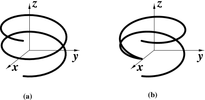
where R denotes the distance from the source to the rotation axis, h the helical pitch, and λs and λe the starting and ending angle of the helical trajectory. In Fig. 1a, we display a two-turn conventional helical trajectory specified by λ∊[λs,λe]=[−2π,2π]. In contrast, the reverse helical trajectory can be written as
| (2) |
where integer n indicates the nth turn, and it can be written in terms of a floor function “⌊⌋” as
| (3) |
Without loss of generality, we have assumed that the turn with n=0 in the reverse helical trajectory is a turn in the conventional helical trajectory. For example, as shown in Fig. 1, for a two-turn reverse helical trajectory specified by λ∊[λs,λe]=[−2π,2π], we have
| (4) |
Figure 1.
A two-turn conventional helical trajectory (a) and a two-turn reverse helical trajectory (b) in the coordinate system {x,y,z} that is fixed on the imaged object.
Let be an object function with a support that is contained completely within the volume enclosed by a reverse helical trajectory. The cone-beam projection from the source point can be written as
| (5) |
where denotes the direction of x-ray transform of from . The task of image reconstruction is to recover from the cone-beam projection data acquired with a reverse helical trajectory specified in Eq. 2.
CHORD-BASED ALGORITHM FOR REVERSE HELICAL TRAJECTORIES
A chord of a continuous trajectory is defined as a line segment connecting any two points on the trajectory. If a volume is covered completely by chords, the image within the volume can be obtained through reconstructing images on all of the chords by use of the chord-based algorithms. Although the chord-based algorithms can have the forms of backprojection filtration (BPF)10 and filtered backprojection (FBP),19 we focus only on image reconstruction for a reverse helical trajectory by using the chord-based BPF algorithm in this section. Similar results can be obtained by use of the chord-based FBP algorithms.
Chord-based BPF algorithm
We consider a chord specified by λ1 and λ2 on a given source trajectory . Let
| (6) |
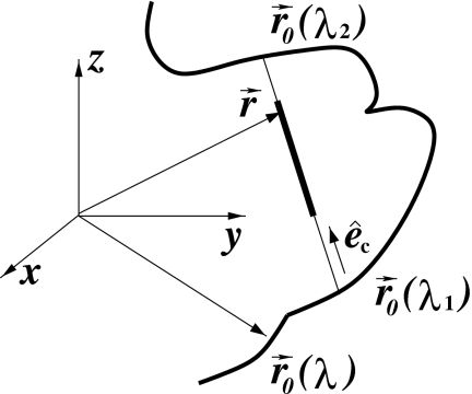
denote the direction of the chord, as shown in Fig. 2. Also, we use xc to indicate the coordinate of a point on the chord. It can be shown that the fixed coordinate and the chord coordinate of the point are related through
| (7) |
where denotes one half of the chord length.
Figure 2.
Illustration of a chord (thin line segment) specified by λ1 and λ2 for a general, continuous trajectory. The direction of the chord is . The thick line segment on the chord indicates the support of the object.
Using fc(xc,λ1,λ2) to denote the object function on the chord, we have
| (8) |
where and xc are related through Eq. 7. Because the compact support of the object function is enclosed by the trajectory, the support of the object function on a chord is finite. Without loss of generality, we assume that the object support on the chord is given by xc∊[xs1,xs2]. Considering a segment [xc1,xc2] on the chord that contains the support xc∊[xs1,xs2], i.e., [xsl,xs2]⊂[xc1,xc2], one has
| (9) |
From cone-beam data , one can compute a backprojection image onto the chord as
| (10) |
where and xc are related through Eq. 7. Based upon the backprojection image on the chord, the BPF algorithm reconstructs the object function fc(xc,λ1,λ2) on the chord as
| (11) |
where xc∊[xc1,xc2], and the constant C is given by
| (12) |
Chord-based reconstructible volume
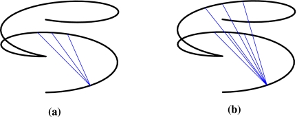
For a reverse helical trajectory, we define a one-turn trajectory segment as the portion in which the rotation direction of the source remains unchanged. The chords of a reverse helical trajectory can thus be divided into two classes: chords connecting two points within a one-turn trajectory segment, and chords connecting two points on two different one-turn trajectory segments, which we refer to as one-turn and multiple-turn chords, respectively. For a one-turn chord specified by λ1 and λ2, ∣λ1−λ2∣≤2π. Therefore, a one-turn chord of a reverse helical trajectory is equivalent to the PI-line segment in a conventional helical trajectory. We display in Figs. 3a, 3b one-turn and multiple-turn chords for a two-turn reverse helical trajectory.
Figure 3.
Illustration of chords (thin line segments) on a two-turn reverse helical trajectory (thick curve): one-turn chords (a), and multiple-turn chords (b).
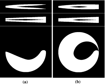
It has been shown that each point enclosed by the conventional helical trajectory is intersected by at least one chord, and consequently that the volume enclosed can be covered completely by chords.16 Therefore, the image within the volume enclosed by the conventional helical trajectory can be reconstructed through reconstructing images on chords intersecting with the volume. In a reverse helical trajectory with a finite number of turns, however, as shown in the Appendix, region(s) exist that are not intersected by any chords, and thus image(s) within the region(s) cannot be reconstructed by use of the chord-based algorithms. For a given reverse helical trajectory, one can determine the reconstructible volume by use of the chord-based algorithm through computing the volume covered by the chords. In Fig. 4, we demonstrate the volumes covered by one-turn chords and multiple-turn chords for a two-turn reverse helical trajectory, which are the reconstructible volumes by use of the chord-based algorithms. Specifically, the white regions in Fig. 4 display the reconstructible areas by use of one-turn chords (a) and multiple-turn chords (b) on the sagittal (top row), coronal (middle row), and transverse (bottom row), respectively. Clearly, regions that are not covered by any chords exist for a two-turn reverse helical trajectory; and the use of multiple-turn chords can increase the reconstructible volume.
Figure 4.
Regions (white) covered by one-turn chords (a) and two-turn chords (b) within slices specified by x=0 (top row), y=0 (middle row), and z=0 (bottom row), respectively. Therefore, the white regions represent the reconstructible regions by use of the chord-based algorithms.
FBP ALGORITHM FOR A REVERSE HELICAL TRAJECTORY
In this section, using Pack–Noo’s formula, we derive a FBP algorithm for image reconstruction from data acquired with a reversed helical trajectory.
Pack–Noo’s reconstruction formula
Pack–Noo’s formula provides a basis for deriving FBP algorithms for image reconstruction for a general source trajectory.17, 20 For a continuous segment of a trajectory that begins and ends at λ− and λ+, we divide it into N adjacent, continuous subsegment trajectories of which the ith subsegment trajectory begins and ends at λi and λi+1, where i=1,2,…N, λ1=λ−, and λN+1=λ+. Therefore, [λ−,λ+]=[λ1,λ2]∪[λ2,λ3]∪⋯[λi,λi+1]∪⋯[λN,λN+1]. For each of the subsegment trajectories, Pack–Noo’s formula provides a reconstruction as
| (13) |
where represents the filtered backprojection data, given by
| (14) |
| (15) |
| (16) |
and
| (17) |
The integration over γ in Eq. 14 indicates a filtering process over the data derivative, while the filtering direction is determined by a preselected unit vector for a subsegment trajectory specified by [λi,λi+1]. As discussed below, the specific form of a derived FBP reconstruction algorithm depends critically upon an appropriate selection of .
For a given subsegment trajectory [λi,λi+1] and a selected unit vector , the reconstruction term , as indicated in Eq. 13, can be computed from cone-beam projections and can thus be interpreted as the known data function. Let denote the second order derivative of the 3D Radon transform of the object function . Pack–Noo’s formula17 establishes a relationship between and as
| (18) |
where
| (19) |
and “sgn” denotes the signum function. Therefore, for the N continuous subsegment trajectories covering the entire trajectory λ∊[λ−,λ+], we have
| (20) |
where
| (21) |
It can be observed that, if the weighting function
| (22) |
the right-hand side of Eq. 20 yields exactly P times the inverse 3D radon transform of the object function. Under the condition in Eq. 22, the object function is obtained as
| (23) |
The result in Eq. 23 is referred to as the FBP reconstruction algorithm, and its derivation, as discussed above, depends upon the appropriate selection of the unit vectors for determining the filtering directions and upon the calculation of .
The FBP algorithm for reverse helical trajectories
Using Pack–Noo’s formula, we derive below a FBP algorithm for image reconstruction from cone-beam data acquired with a two-turn reverse helical trajectory. Extension of the derived algorithm to multiple-turn reverse helical trajectories is straightforward and will be briefly described.
For a continuous scanning trajectory, one can define a polygon plane as the plane that intersects the trajectory at more than two points. For each side of a polygon, there exists a continuous subsegment of the source trajectory connecting two ends of the side of the polygon. Based on Pack–Noo’s formula, a polygon-based FBP algorithm has been developed for image reconstruction for circular sinusoidal trajectories, including the saddle trajectory.18 For a circular sinusoidal trajectory, without loss of generality, we consider a polygon of four sides that intersects the trajectory four times. Let unit vectors denote the directions of the polygon sides, i.e.,
| (24) |
where λi and λi+1 denote the starting and ending points of the ith subsegment trajectory corresponding to the ith side of the polygon, and i=1,2,3, and 4. In this case, it has been shown18, 21 that
| (25) |
where λ−=λ1, λ+=λ5, and . Using this result in Eq. 23, one obtains the FBP algorithm for exact image reconstruction within the polygon, which is written as
| (26) |
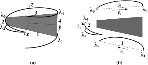
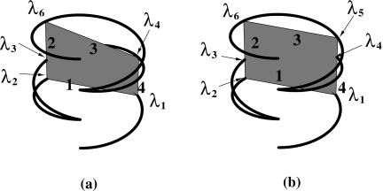
We now extend the FBP algorithm above to reconstruct images for a two-turn reverse helical trajectory depicted in Fig. 5. First of all, it is important to observe, for a given point within and the side direction of the polygon, that both and depend only upon the starting and ending points λi and λi+1, while being independent of the shape of the continuous subsegment trajectory corresponding to side i of the polygon. Therefore, the results in Eqs. 25, 26 are directly applicable to image reconstruction within a four-side polygon defined on a general trajectory, under the conditions that (1) λ−=λ1, λ+=λ5, and and (2) each side of the polygon has a continuous subsegment trajectory connecting the two ends of the side.
Figure 5.
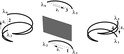
(a) The four-side polygon (shaded region) formed by four chords each of which connects two points on the two-turn reverse helical trajectory. The polygon plane is chosen to be parallel to y-z plane. (b) Continuous subsegment trajectories (thick curves) corresponding to sides i of the four-side polygon (dashed lines), and the directions of the chords (i.e., the sides) of the polygon, where i=1,2, and 3.
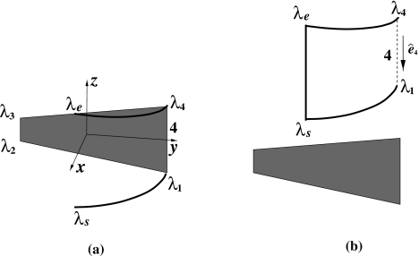
Consider a polygon plane in Fig. 5a that is parallel to the y-z plane and that intersects the reverse helical trajectory at four distinctive points , where i=1,…,4; and −2π≤λ1<λ2⋯<λ4≤2π. It can be observed in Fig. 5b that each of sides 1, 2, and 3 of the polygon has a distinct, continuous subsegment trajectory connecting its two ends. However, side four of the polygon has a distinct, discontinuous subsegment trajectory, which contains the starting and ending points λs and λe of the reverse helical trajectory, as displayed in Fig. 6a. Therefore, Eq. 26 cannot directly be applied to reconstructing an exact image within the polygon for the reverse helical trajectory.
Figure 6.
(a) For side four of the polygon (shade region), the subsegment trajectory containing the starting and ending points λs and λe consists of two discontinuous segments (thick curves). (b) A continuous subsegment trajectory passing λs and λe can be formed for side four through including, e.g., an additional, straight subsegment trajectory connecting λs and λe. Again, denotes the direction of side four (dashed line) of the polygon.
A continuous subsegment trajectory for side four may be formed through including an additional continuous subsegment trajectory that connects the starting point λs and the ending point λe of the two-turn reverse helical trajectory. For example, a continuous subsegment trajectory passing λs and λe is formed in Fig. 6b, which includes an additional, straight subsegment trajectory connecting λs and λe. However, an additional subsegment trajectory requires an additional scan, thus resulting in additional scanning effort and radiation dose.
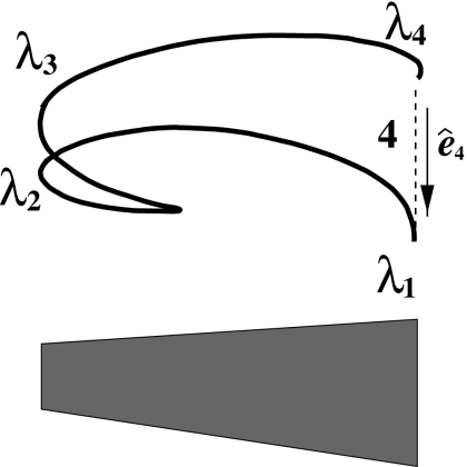
It is indeed possible to identify a continuous subsegment trajectory for side four without involving any additional scan to the reverse helical trajectory.22 As shown in Fig. 7, the union of the three distinct subsegment trajectories corresponding to sides 1, 2, and 3 of the polygon forms a continuous subsegment trajectory for side four of the polygon. As mentioned above, is independent of the shape of the continuous subsegment trajectory, while depending only upon λ4 and λ5, where λ5 satisfies . Therefore, we can use the union of three distinct subsegment trajectories of sides 1, 2, and 3 to compute . In fact, from Eq. 5 and Eqs. 13, 14, 15, 16, 17, it can be seen that depends upon λi and λi+1 through and . Therefore,
| (27) |
in which we have used . Furthermore, using Eq. 13, one can readily show that
| (28) |
Finally, an exact image reconstruction within the polygon for a two-turn reverse helical trajectory can be obtained as
| (29) |
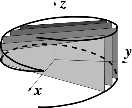
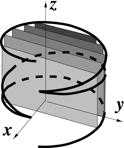
We refer to Eq. 29 as the FBP algorithm for image reconstruction for a reverse helical trajectory. As shown in Fig. 8, the volume enclosed by a reverse helical trajectory can be decomposed into a set of polygons. Therefore, one can achieve a volume-image reconstruction for a reverse helical trajectory through reconstructing images within the set of polygons by use of the FBP algorithm described.
Figure 7.
The portion of a two-turn reverse helical trajectory passing through λ2 and λ3 forms a continuous subsegment trajectory for side four of the polygon in Fig. 5.
Figure 8.
The volume enclosed by a two-turn reverse helical trajectory can be decomposed into a set of parallel polygons. Without loss of generality, a set of polygons parallel to y-z plane is shown. A volume image can be obtained through reconstructing images within the polygons by use of the proposed FBP algorithm.
The FBP algorithm above was derived for a two-turn reverse helical trajectory. Similar approach can readily be applied to deriving an FBP algorithm for multiple-turn reverse helical trajectories. Without loss of generality, we use a three-turn reverse helical trajectory to illustrate such an extension. Again, for the given reverse helical trajectory, we first select a four-side polygon whose four corners reside on the trajectory, as shown in Fig. 9. In the case of a multiple-turn reverse helical trajectory, different polygons can be devised. In Figs. 9a, 9b, two different four-side polygons are displayed. In these cases, it can be readily shown that, when unit vectors are selected along each of the sides of the polygon, the result in Eq. 25 remains unchanged. Furthermore, a continuous subsegment trajectory can be identified for each side of the polygon. In Fig. 10, we display the continuous subsegment trajectories for each side of the polygon in Fig. 9b. From these continuous subsegment trajectories, one can compute and use them in Eq. 29 to obtain the image within the polygon. Finally, one can obtain a volume image by reconstructing 2D images within a set of polygons in the volume enclosed by the reverse helical trajectories, as displayed in Fig. 11.
Figure 9.
(a) A polygon with four corners intersecting the three-turn reverse helical trajectory at λ1, λ2, λ4, and λ6. (b) A polygon with four corners intersecting the three-turn reverse helical trajectory at λ1, λ2, λ5, and λ6.
Figure 10.
The continuous subsegment trajectories corresponding to each side of the polygon in Fig. 9b.
Figure 11.
The volume enclosed by a three-turn reverse helical trajectory can be decomposed into a set of parallel polygons. A set of polygons parallel to y-z plane is shown here. A volume image can be obtained through reconstructing images within the polygons.
NUMERICAL RESULTS
We have performed computer simulation studies to validate that the proposed FBP algorithm can reconstruct images within the volume enclosed by a reverse helical trajectory, including the chordless regions that cannot be reconstructed by use of the chord-based algorithm. A low contrast 3D Shepp–Logan phantom was used that has an ellipsoid support with axes of 13.8, 18.0, and 18.4 cm along the x, y, and z axis, respectively. Additionally, a high contrast shoulder phantom was also used that has an ellipsoid support with axes of 16.0, 8.0, and 8.0 cm along the x, y, and z axis, respectively. The shoulder phantom has been designed specifically to supply z-slice images that look like FORBILD thorax phantom and also to prevent data truncation for this study.23 The details of the shoulder phantom are described in Table 1. In the phantom, different types of objects are included: cut ellipsoid (CE) that has cuts along long axis, ellipsoid (E), cone (CN), and cylinder (CL). Parameters represent half lengths of long axis and two other short axes for CE and E; top radius, bottom radius, and height for CN; and radius and height for CL. Polar (θ) and azimuthal (ϕ) angles are given in degrees. All the lengths are in relative units, and the phantom has been resized in the numerical study. The reverse helical trajectories have radii of R=60 cm and the distances of D=75 cm from the sources to detectors. The number of projections per turn is 800. We used helical pitch of h=40 cm in the simulation study for the proposed FBP algorithm. For the purpose of clearly demonstrating the chordless region in the reconstruction, we used a helical pitch of h=15 cm in the simulation study involving the chord-based BPF algorithm. When h=40 cm is used for the chord-based BPF algorithm study, the phantom would be barely reconstructed that the difference between the images, reconstructed by use of only one-turn chords and two-turn chords as well, is small. The detector panel considered here has an effective square area that consists of 400×400 pixels each of which has a size of 0.78×0.78 mm2. Image reconstruction volume consists of 400×400×400 voxels each of which has a size of 0.61×0.61×0.61 mm3. Similar discretization rules to those in Ref. 21 have been used in the implementation of the algorithm, which are summarized in the Appendix B.
Table 1.
Shoulder phantom description.
| Type | Center | Parameters | Cut-length | Angles (θ,ϕ) | Density |
|---|---|---|---|---|---|
| CE | 0,0,0 | 80,40,40 | −70,70 | 0,0 | 1.5 |
| CE | −80,0,0 | 22,22,22 | −22,10 | 0,0 | 1.5 |
| CE | 80,0,0 | 22,22,22 | −10,22 | 0,0 | 1.5 |
| E | −88,0,0 | 10,10,10 | 0,0 | 2.3 | |
| E | −88,0,0 | 8,8,8 | 0,0 | 1.5 | |
| E | 88,0,0 | 10,10,10 | 0,0 | 2.3 | |
| E | 88,0,0 | 8,8,8 | 0,0 | 1.5 | |
| E | −65,0,0 | 10,10,10 | 0,0 | 2.3 | |
| E | −65,0,0 | 8,8,8 | 0,0 | 1.5 | |
| E | 65,0,0 | 10,10,10 | 0,0 | 2.3 | |
| E | 65,0,0 | 8,8,8 | 0,0 | 1.5 | |
| E | 0,20,0 | 5,5,5 | 0,0 | 2.3 | |
| CE | 0,20,0 | 6.5,6.5,6.5 | −5.5,6.5 | 0,−90 | 3.0 |
| CN | 0,27.5,0 | 3.5,15,4 | 0,0 | 3.0 | |
| CL | 0,33,0 | 1.5,7 | 90,90 | 3.0 | |
| E | −40,20,0 | 23,3,3 | 0,20 | 2.3 | |
| E | −40,20,0 | 18,2,2 | 0,20 | 1.5 | |
| E | 40,20,0 | 23,3,3 | 0,−20 | 2.3 | |
| E | 40,20,0 | 18,2,2 | 0,−20 | 1.5 | |
| CL | 0,−36,0 | 2,9 | 90,0 | 2.3 | |
| CL | 0,−36,0 | 1,7 | 90,0 | 1.5 | |
| CE | 12,−35,0 | 13,2,2 | −1,13 | 0,20 | 2.3 |
| CE | 12,−35,0 | 10,1,1 | 0,10 | 0,20 | 1.5 |
| CE | −12,−35,0 | 13,2,2 | −13,1 | 0,−20 | 2.3 |
| CE | −12,−35,0 | 10,1,1 | −10,0 | 0,−20 | 1.5 |
| E | −20,5,0 | 4,5,5 | 0,0 | 2.0 | |
| E | −10,−15,0 | 13,15,10 | 0,−30 | 2.0 | |
| E | 20,5,0 | 12,10,10 | 0,30 | 2.0 |
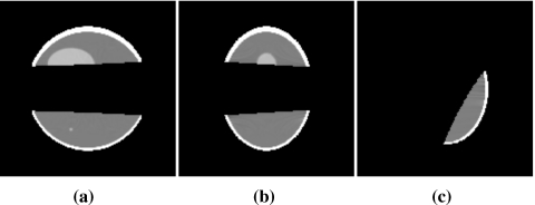
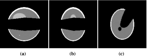
In Figs. 1213, we display images of the Shepp–Logan phantom within slices at (a) x=0 cm, (b) y=0 cm, and (c) z=−2.5 cm reconstructed on one-turn and multiple-turn chords by using the chord-based BPF algorithm. Clearly, the BPF algorithm can accurately reconstruct images within the regions covered the chords. Comparison of the reconstructive regions in Figs. 1213 indicates that the use of multiple-turn chords leads to a larger reconstructible region than that only from the one-turn chords. However, it can also be observed in both cases that the BPF algorithm cannot yield images within the chordless regions (e.g., the dark regions between the two reconstructible regions).
Figure 12.
Images of the Shepp–Logan phantom within slices at (a) x=0 cm, (b) y=0 cm, and (c) z=−2.5 cm reconstructed from noiseless data by use of the chord-based algorithm on one-turn chords. Display window is [1.0,1.04].
Figure 13.
Images of the Shepp–Logan phantom within slices at (a) x=0 cm, (b) y=0 cm, and (c) z=−2.5 cm reconstructed from noiseless data by use of the chord-based algorithm on both one-turn and two-turn chords. Display window is [1.0,1.04].
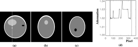
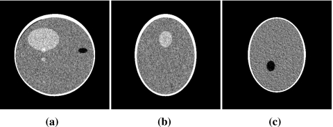
In Fig. 14, we show images of the Shepp–Logan phantom within slices at (a) x=0 cm, (b) y=0 cm, and (c) z=−2.5 cm reconstructed by using the proposed FBP algorithm. The results indicate that the proposed algorithm can reconstruct an image within the volume enclosed by a reverse helical trajectory. In an attempt to demonstrate quantitatively the reconstruction accuracy, we display in Fig. 14d the profile along a vertical line, specified by x=0 cm and y=−2.5 cm, passing through the Shepp–Logan phantom, as indicated in Fig. 14a. For comparison, we also plot the corresponding true profile as dotted curve in Fig. 14d. The profile results suggest that the proposed FBP algorithm can accurately reconstruct an image within the entire volume enclosed by the reverse helical trajectory. We have also performed a preliminary reconstruction from noisy data by use of the proposed FBP algorithm. We included Gaussian noise in the projection data with the noise level of 0.25%. From the noisy data, we reconstructed images by use of the proposed FBP algorithm. In Fig. 15, we display the reconstructed noisy images within slices at (a) x=0 cm, (b) y=0 cm, and (c) z=−2.5 cm.
Figure 14.
Images of the Shepp–Logan phantom within slices at (a) x=0 cm, (b) y=0 cm, and (c) z=−2.5 cm reconstructed from noiseless data by use of the proposed FBP algorithm. Display window is [1.0,1.04]. (d) Profile on the vertical line specified by x=0 cm and y=−2.5 cm, which is also indicated in (a). The reconstructed and true profiles are displayed as solid and dotted curves, respectively.
Figure 15.
Images of the Shepp–Logan phantom within slices at (a) x=0 cm, (b) y=0 cm, and (c) z=−2.5 cm reconstructed from the noisy data by use of the proposed FBP algorithm. Display window is [1.01,1.03].
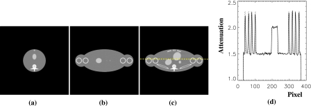
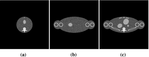
In Fig. 16, we show images of the shoulder phantom within slices at (a) x=0 cm, (b) y=0 cm, and (c) z=0 cm reconstructed by using the proposed FBP algorithm. We also display in Fig. 16d the profile along a horizontal line, specified by y=0.5 cm and z=0 cm, passing through the phantom, as indicated in Fig. 16c. Corresponding true profile is represented by a dotted curve in Fig. 16d. These results indicate the proposed algorithm can reconstruct high contrast variations accurately as well although some image artifacts due to discretization errors are observable such as streaks in Fig. 16c. We included Gaussian noise in the projection data with the noise level of 1.0%. From the noisy data, we reconstructed images by use of the proposed FBP algorithm. In Fig. 17, we display the reconstructed noisy images within slices at (a) x=0 cm, (b) y=0 cm, and (c) z=0 cm.
Figure 16.
Images of the shoulder phantom within slices at (a) x=0 cm, (b) y=0 cm, and (c) z=0 cm reconstructed from noiseless data by use of the proposed FBP algorithm. Display window is [1.0,2.5]. (d) Profile on the horizontal line specified by y=0.5 cm and z=0 cm, which is also indicated in (c). The reconstructed and true profiles are displayed as solid and dotted curves, respectively.
Figure 17.
Images of the shoulder phantom within slices at (a) x=0 cm, (b) y=0 cm, and (c) z=0 cm reconstructed from the noisy data by use of the proposed FBP algorithm. Display window is [1.0,2.5].
DISCUSSION
In the work, we have proposed reverse helical trajectories for acquiring cone-beam data, and have investigated and developed algorithms for image reconstruction from such cone-beam data. The proposed reverse helical trajectories and reconstruction algorithms may find use in IGRT and other applications. Recently, chord-based algorithms such as the BPF algorithm have been developed for image reconstruction from data acquired with general trajectories, provided that the trajectories have chords covering the object. However, reverse helical trajectories are unique in that, although they satisfy Tuy’s sufficient data condition for nontruncated object, certain parts of the volume enclosed by them are not covered by chords. Consequently, the chord-based algorithms cannot reconstruct images within the chordless regions of reverse helical trajectories. For a given reverse helical trajectory, we have investigated its chordless regions; and we then conducted image reconstruction by use of the chord-based BPF algorithm to demonstrate the nonreconstructible, chordless regions.
As mentioned above, however, the volume enclosed by a reverse helical trajectory satisfies Tuy’s condition, suggesting that exact image of an object within the reverse helix volume including the chordless regions can be reconstructed. We have proposed a FBP algorithm based on Pack–Noo’s formula to reconstruct the images within the volume enclosed by a reverse helical trajectory, thus eliminating the chordless region that is nonreconstructible by use of the chord-based algorithms. Numerical studies were also conducted to validate the proposed FBP algorithm. Results of the numerical studies confirm that, unlike the chord-based algorithm, the proposed FBP algorithm can reconstruct an accurate image for the entire reverse helix volume. Since the proposed algorithm is of FBP type, it is in general computationally efficient. However, data filtering has to be performed at least twice for each projection, which may increase the amount of computation compared to a conventional FBP algorithm.
Interestingly, the developed FBP algorithm allows certain transverse data truncation. This is because the data filtering is determined only by the directions of the polygon sides within which the image is to be reconstructed. When the polygons covering the reverse helix volume are selected to be, e.g., parallel to the y-z plane, as we did here, data truncation along the x axis outside the volume covered by the polygons does not affect the image-reconstruction accuracy within these polygons. However, the proposed FBP algorithm generally allows no truncation longitudinally and is thus incapable of dealing with a long object problem. For a reverse helical trajectory with a long object problem, we are developing a combined image-reconstruction method in which the chord-based algorithm is used for addressing the long object problem, and the proposed FBP algorithm is used for dealing with image reconstruction within the chordless regions. The research of this combined method is beyond the scope of the current work and will be reported elsewhere in the future. We have also discussed the extension of the proposed FBP algorithm to reconstruct images for multiple-turn reverse helical trajectories. In fact, it should be pointed out that the proposed FBP algorithm can readily be generalized to address the problems of image reconstruction for reverse helical trajectories with tilted axis, or variable pitches, or additional scanning trajectory segments.
ACKNOWLEDGMENTS
S.C. is supported in part by DOD Predoctoral training Grant No. PC061210, and D.X. is supported in part by DOD Predoctoral training Grant No. BC051553. This work was also supported in part by National Institutes of Health Grant Nos. EB00225 and CA120540. Its contents are solely the responsibility of the authors and do not necessarily represent the official views of the National Institutes of Health. The authors would like to thank Dr. Yu Zou for his help on shoulder phantom.
APPENDIX A: ANALYSIS OF THE CHORDLESS REGIONS IN A REVERSE HELICAL TRAJECTORY
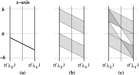
It is shown here that there exist chordless regions in the volume enclosed by a two-turn reverse helical trajectory. For simplifying the discussion, we consider intersecting points along z axis, which is the rotation axis, with all the possible chords, and we show that there exists a region between intersecting regions on z axis. A chord passing through z axis defines a unique plane containing the chord and z axis. For a given chord passing through z axis, we label the angular parameter of the lower end by λ1 and that of the upper end by λ2. A chord, for example, is presented on the defined plane in Fig. 18. Using circular symmetry, we can establish the functional relationship, as summarized in Table 2, between z(λ1) and z(λ2) for one-turn chords and also for multiple-turn chords, where z(λ) indicates the z coordinate of a source point on the reverse helical trajectory at λ. The z-coordinate, z0(λ1,λ2), of the intersecting point of a chord withz axis is given by
| (A1) |
which is in the shaded regions in Figs. 18a, 18b for one-turn and multiple-turn chords. The chordless (white) region can be observed between the intersecting (shaded) regions.
Figure 18.
Diagrams demonstrating the chordless region along z axis for a two-turn reverse helical trajectory. (a) An exemplary chord plotted on the plane defined by the chord and z axis. (b) Collection of all one-turn chords. (c) Collection of all chords including multiple-turn chords.
Table 2.
Relationship between the z coordinates of chords passing through z axis for a two-turn reverse helical trajectory.
| λ1 | −2π≤λ1≤−π | −π<λ1<0 | 0≤λ1≤π | π<λ1≤2π | |
|---|---|---|---|---|---|
| z(λ1) | h∕2π(λ1) | h∕2π(λ1) | h∕2π(λ1) | h∕2π(λ1) | |
| One-turn chords | z(λ1) | h∕2π(λ1+π) | None | h∕2π(λ1+π) | None |
| Multiple-turn chords | z(λ2) | h∕2π(−λ1−π) | h∕2π(−λ1+π) | None | None |
APPENDIX B: IMPLEMENTATION OF THE PROPOSED FBP ALGORITHM
For discussion of algorithm implementation, we introduce a rotation-coordinate system {u,v,w} in which its origin is on the source , and its u-w plane and v axis are parallel to the x-y plane and to the z axis, respectively, of the fixed-coordinate system {x,y,z}. The unit vectors of the rotation-coordinate system at a scanning angle λ can be expressed in the fixed-coordinate system as
| (B1) |
Let the flat-panel detector be placed within a plane at w=−D that is parallel to the u-v plane. We introduce a 2D-detector-coordinate system {ud,vd} on the plane in which the ud and vd axes are parallel to the u and v axes, respectively, and its origin is at the projection, along , on the detector plane, of the source point . For a point on the detector plane, the relationship between its fixed coordinates (xd,yd,zd) and 2D-detector coordinates (ud,vd) can be obtained as
| (B2) |
Now the three steps of the algorithm can be summarized as follows.
Data derivative: We compute
| (B3) |
Three points differentiation method has been used for computing derivatives.
Hilbert transform: For given filtering direction , we compute 1D Hilbert transform along the projection of at image point onto the detector as
| (B4) |
where hH(u) is the kernel of Hilbert transform, , and . Upper and lower integration boundaries can be either (−∞,∞) or (∞,−∞) depending on the relative position with respect to the reconstruction point . Rebinning and back-rebinning method similar to that used in Ref. 21 has been used for integration.
Backprojection: We compute
| (B5) |
Bilinear interpolation has been used for computing the backprojection.
References
- Jaffray D. A. and Siewerdsen J. H., “Cone-beam computed tomography with a flat-panel imager: Initial performance characterization,” Med. Phys. 10.1118/1.599009 27, 1311–1323 (2000). [DOI] [PubMed] [Google Scholar]
- Siewerdsen J. H. and Jaffray D. A., “Optimization of x-ray imaging geometry (with specific application to flat-panel cone-beam computed tomography),” Med. Phys. 10.1118/1.1286590 27, 1903–1914 (2000). [DOI] [PubMed] [Google Scholar]
- Groh B. A., Siewerdsen J. H., Drake D. G., Wong J. W., and Jaffray D. A., “A performance comparison of flat-panel imager-based MV and kV cone-beam CT,” Med. Phys. 10.1118/1.1477234 29, 967–975 (2002). [DOI] [PubMed] [Google Scholar]
- Feldkamp L. A., Davis L. C., and Kress J. W., “Practical cone-beam algorithm,” J. Opt. Soc. Am. A1, 612–619 (1984). [Google Scholar]
- Mori S., Endo M., Komatsu S., Kandatsu S., Yashiro T., and Baba M., “A combination-weighted Feldkamp-based reconstruction algorithm for cone-beam CT,” Phys. Med. Biol. 10.1088/0031-9155/51/16/005 51, 3953–3965 (2006). [DOI] [PubMed] [Google Scholar]
- Valton S., Peyrin F., and Sappey-Marinier D., “Analysis of cone-beam artifacts in off-centered circular CT for four reconstruction methods,” Int. J. Biomed. Imaging 2006, 1–8 (2006). [DOI] [PMC free article] [PubMed] [Google Scholar]
- Yoo S. and Yin F., “TU-FF-A2-01: Feasibility of cone-beam CT based treatment planning,” Med. Phys. 33, 2219 (2006). [DOI] [PubMed] [Google Scholar]
- Katsevich A., “Theoretically exact FBP-type inversion algorithm for spiral CT,” SIAM J. Appl. Math. 10.1137/S0036139901387186 62, 2012–2026 (2002). [DOI] [Google Scholar]
- Noo F., Pack J., and Heuscher D., “Exact helical reconstruction using native cone-beam geometries,” Phys. Med. Biol. 10.1088/0031-9155/48/23/001 48, 3787–3818 (2003). [DOI] [PubMed] [Google Scholar]
- Zou Y. and Pan X., “Exact image reconstruction on PI-line from minimum data in helical cone-beam CT,” Phys. Med. Biol. 10.1088/0031-9155/49/6/006 49, 941–959 (2004). [DOI] [PubMed] [Google Scholar]
- Ye Y. and Wang G., “Filtered backprojection formula for exact image reconstruction from cone-beam data along a general scanning curve,” Med. Phys. 10.1118/1.1861792 32, 654–665 (2005). [DOI] [PubMed] [Google Scholar]
- Pack J. D., Noo F., and Clackdoyle R., “Cone-beam reconstruction using the backprojection of locally filtered projections,” IEEE Trans. Med. Imaging 24, 2317–2336 (2005). [DOI] [PubMed] [Google Scholar]
- Zou Y., Pan X., and Sidky E. Y., “Theory and algorithms for image reconstruction on chords and within regions of interest,” J. Opt. Soc. Am. 22, 2372–2384 (2005). [DOI] [PubMed] [Google Scholar]
- Katsevich A., “Image reconstruction for the circle-arc trajectory,” Phys. Med. Biol. 10.1088/0031-9155/50/10/005 50, 2249–2265 (2005). [DOI] [PubMed] [Google Scholar]
- Zhuang T. and Chen G., “New families of exact fan-beam and cone-beam image reconstruction formulae via filtering the backprojection image of differentiated projection data along singly measured lines,” Inverse Probl. 10.1088/0266-5611/22/3/016 22, 991–1006 (2006). [DOI] [Google Scholar]
- Danielsson P. E., Edholm P., and Seger M., “Towards exact 3D-reconstruction for helical cone-beam scanning of long objects. A new detector arrangement and a new completeness condition,” in Proceedings of the 1997 International Meeting on Fully Three-Dimensional Image Reconstruction in Radiology and Nuclear Medicine, edited by Townsend D. W. and Kinahan P. E., Pittsburgh, 1997.
- Pack J. D. and Noo F., “Cone-beam reconstruction using 1D filtering along the projection of M-lines,” Inverse Probl. 10.1088/0266-5611/21/3/019 21, 1105–1120 (2005). [DOI] [Google Scholar]
- Yang H., Li M., Koizumi K., and Kudo H., “Application of Pack and Noo’s cone-beam inversion formula to a wide class of trajectories,” in IEEE Medical Imaging Conference Record, San Diego, CA, 2006, pp. M14–450.
- Sidky E. Y., Zou Y., and Pan X., “Minimum data image reconstruction algorithms with shift-invariant filtering for helical, cone-beam CT,” Phys. Med. Biol. 10.1088/0031-9155/50/8/002 50, 1643–1657 (2005). [DOI] [PubMed] [Google Scholar]
- Pack J. D. and Noo F., “Cone-beam reconstruction outside R-lines using the backprojection of 1-D filtered data,” in Proceedings of the 2005 International Meeting on Fully Three-Dimensional Image Reconstruction in Radiology and Nuclear Medicine, Salt Lake City, UT, pp. 287–290 (2005).
- Yang H., Li M., Koizumi K., and Kudo H., “Exact cone beam reconstruction for a saddle trajectory,” Phys. Med. Biol. 10.1088/0031-9155/51/5/008 51, 1157–1172 (2006). [DOI] [PubMed] [Google Scholar]
- Xia D., Cho S., and Pan X., “Image reconstruction for cone-beam CT with reduced-scan circular sinusoidal trajectories,” IEEE Trans. Med. Imaging (submitted).
- http://www.imp.uni erlangen.de/phantoms/thorax/thorax.htm


