Abstract
Safety concerns exist for potential thermal damage at tissue-air or tissue-bone interfaces located in the post-focal region during high intensity focused ultrasound (HIFU) treatments. We tested the feasibility of reducing thermal energy deposited at the post-focal tissue-air interfaces by producing bubbles (due to acoustic cavitation and∕or boiling) at the HIFU focus. HIFU (in-situ intensities of 460–3500 W∕cm2, frequencies of 3.2–5.5 MHz) was applied for 30 s to produce lesions (in turkey breast in-vitro (n=37), and rabbit liver (n=4) and thigh muscle in-vivo (n=11)). Tissue temperature was measured at the tissue-air interface using a thermal (infrared) camera. Ultrasound imaging was used to detect bubbles at the HIFU focus, appearing as a hyperechoic region. In-vitro results showed that when no bubbles were present at the focus (at lower intensities of 460–850 W∕cm2), the temperature at the interface increased continuously, up to 7.3±4.0 °C above the baseline by the end of treatment. When bubbles formed immediately after the start of HIFU treatment (at the high intensity of 3360 W∕cm2), the temperature increased briefly for 3.5 s to 7.4±3.6 °C above the baseline temperature and then decreased to 4.0±1.4 °C above the baseline by the end of treatment. Similar results were obtained in in-vivo experiments with the temperature increases (above the baseline temperature) at the muscle-air and liver-air interfaces at the end of the high intensity treatment lower by 7.1 °C and 6.0 °C, respectively, as compared to the low intensity treatment. Thermal effects of HIFU at post-focal tissue-air interfaces, such as in bowels, could result in clinically significant increases in temperature. Bubble formation at the HIFU focus may provide a method for shielding the post-focal region from potential thermal damage.
Keywords: HIFU, focused ultrasound, cavitation, boiling, bubbles, thermal damage, reflection, scattering, tissue-air interface, safety considerations
INTRODUCTION
High intensity focused ultrasound (HIFU) provides a method for extracorporeal delivery of a large amount of acoustic energy to a millimeter-size focal spot in tissues located deep inside the body, while sparing intervening and surrounding tissues from harmful exposure.1 Large energy levels result in temperatures rising above 70 °C at the HIFU focus, within seconds, leading to coagulation necrosis of pathological tissues. In recent years, HIFU therapy has gained a significant momentum resulting from a number of successful clinical applications, especially in the treatment of benign and malignant tumors.1, 2, 3, 4, 5 HIFU therapy utilizes a variety of focused ultrasound sources (both single-element transducers and phased arrays) that target the tumor through an acoustic window consisting primarily of soft tissues. If a suitable acoustic window is present, coagulation necrosis of pathological tissues can be produced at the focal spot of HIFU, and the treatment proceeds to cover a pre-determined tumor volume.6, 7 In these treatments, it is assumed that the divergence of the HIFU beam beyond the focus results in low ultrasound intensities that cannot produce any unwanted tissue effects.8 However, the presence of bones or gas pockets in the post-focal region could potentially lead to thermal tissue damage due to the increase in delivered energy at the soft tissue boundaries with air or bone.9, 10
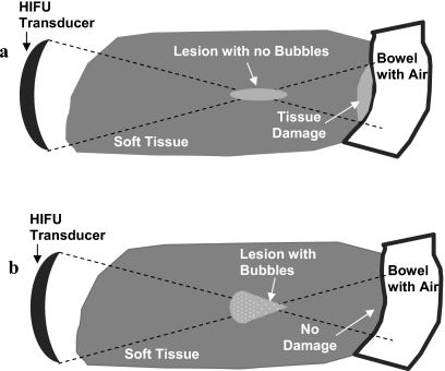
Currently, a number of HIFU applications focus on the extracorporeal treatment of tumors located in the solid organs of the abdomen.1, 5, 11 This anatomical location is of potential concern in HIFU treatments due to the presence of gas pockets in the stomach and intestines.1 These gas pockets have to be avoided if they are located in the pre-focal region of the propagation path of the HIFU beam, because they interfere with the focusing ability of HIFU,12 and hinder treatment success.1 Gas pockets located post-focally also represent a problem, due to the impedance mismatch at soft tissue-air interface,13 which results in the increase of the delivered acoustic energy at the interface, potentially causing unwanted tissue heating.8 One solution to this problem is to design HIFU treatments such that the interface (with air or bone) is located sufficiently far away in the post-focal region, where no significant temperature increase can occur. This approach has been applied during extracorporeal HIFU treatment of uterine fibroids, where the treatment zone has to be at least 4 cm away from sensitive structures located in the close bone proximity.14 However, the need for large margins between the HIFU treatment zone and the post-focal interface limits the type and location of tumors that can be treated with HIFU.1 Another potential solution, investigated in the study reported here, is to achieve shielding of the post-focal region from unwanted thermal effects by producing bubbles at the HIFU focus (Fig. 1).15, 16 The presence of gas or vapor bubbles at the focus, resulting from mechanical effects of HIFU and∕or boiling,17 hinders the propagation of HIFU beam to the post-focal region,15, 16 thus potentially preventing significant temperature increase at the soft tissue-air or soft tissue-bone interfaces. Our results, obtained in turkey breast in-vitro and rabbit muscle and liver in-vivo, showed that the temperatures at the tissue-air interface were significantly lower during the high intensity treatments, which resulted in the bubble formation at the HIFU focus, as compared to the low intensity treatments, which resulted in no bubble formation.
Figure 1.
Soft tissue-air interface in the HIFU post-focal region. (a) Schematic of the HIFU treatment with no bubbles present at the focus. Reflection at the soft tissue-air interface may result in the thermal damage in healthy tissues. (b) Schematic of the HIFU treatment in which bubbles were produced at the focus, impeding the propagation of the HIFU beam beyond focus. No thermal damage is expected at the post-focal soft tissue-air interface in this case.
MATERIALS AND METHODS
In-vitro experiments
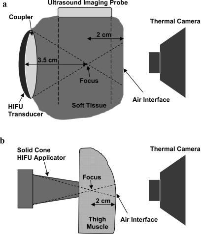
Turkey breast meat was obtained from a local store, and cut into ten pieces with a thickness of 4 cm, length of 15 cm, and width of 6 cm. Before the HIFU treatment, each piece of tissue was placed in a custom-made acrylic plastic fixture facing an air window (15 cm long by 4 cm wide), which was covered with a thin (less than 0.1 mm) sheet made of transparent acetate. This sheet reflected less than 2% of ultrasound waves.13 The schematic of the experimental set-up is shown in Fig. 2a. A HIFU transducer was positioned opposite to the air window with the tissue in between. The tissue-air interface was located in the post-focal region at 2 cm from the HIFU focus. During the treatment, a thermal (infrared) camera (S60, FLIR, Goleta, CA, USA) was used to observe the tissue-air interface, while the ultrasound imaging probe was used to interrogate the HIFU focal region. In each turkey breast piece, the lesions were located at least 2.5 cm apart, to assure no overlapping of the lesions.
Figure 2.
In-vitro and in-vivo experimental setups. The temperature at the tissue-air interface in the post-focal region was measured using a thermal camera. (a) Treatment of the turkey breast in-vitro was performed using a 3.2 MHz HIFU device (focus at 3.5 cm). HIFU focus was observed using B-mode ultrasound imaging. (b) In-vivo treatment was performed using an intraoperative 5.5 MHz HIFU solid cone applicator (with the focus located at ∼1 cm from the tip of the applicator).
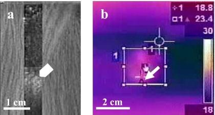
Treatments were performed using a 3.2 MHz HIFU device (diameter of 3.3 cm, focal distance of 3.5 cm, Sonic Concepts, Bothell, WA, USA) which was attached to an ultrasound imaging probe (CL10-5, HDI 3000, Philips, Bothell, WA, USA) using a custom-made holder. B-mode ultrasound imaging and HIFU were synchronized (with 77% duty cycle) as described previously18 to allow observation of hyperecho formation at the HIFU focus [arrowhead, Fig. 3a]. The formation of hyperecho (i.e., bright region in ultrasound images) was shown previously to be an indication of the presence of bubbles at the HIFU focus, and correlate well with the cavitation signal obtained using passive and active cavitation detection.19, 20, 21 Coupling between the HIFU transducer and tissue was achieved via a custom-made polyurethane water pillow.22 The water pillow was attached to a circulating pump to provide transducer cooling. The −3 dB width and length of the HIFU focus, obtained using hydrophone field measurements, were 0.8 and 5.1 mm, respectively. The free-field ultrasound intensities were calculated from the acoustic power (measured using a radiation force balance) divided by the focal area.13 The in-situ intensities were calculated by derating the free-field intensities by the duty cycle and the tissue attenuation through 2 cm of turkey breast (attenuation of 0.15 Np∕cm∕MHz).13 The energy dose was obtained by multiplying the in-situ intensity with the HIFU treatment duration of 30 s. The number of experiments per different intensities was: 11 at 460 W∕cm2, 8 at 650 W∕cm2, 9 at 850 W∕cm2, and 9 at 3360 W∕cm2.
Figure 3.
A representative ultrasound (a) and thermal image (b) obtained during the in-vitro HIFU treatment at the high in-situ intensity of 3360 W∕cm2. Hyperecho formation at the HIFU focus (arrowhead). Cursor of the thermal camera was able to track the highest temperature in real time (arrow).
An infrared thermal camera (S60, FLIR) was used to measure the temperature at the tissue-air interface. The camera had a cursor [arrow, Fig. 3b] that could automatically track the highest temperature in the specified region. The temperatures were shown on the camera screen in real time. The accuracy of thermal reading was 2% of the maximal measured temperature (better than 0.7 °C in our in-vitro experiments). The screen of the thermal camera was continuously recorded on a VCR tape for later analysis. Movies of thermal measurements were imported into Adobe Premier (San Jose, CA, USA) and digitized. These movies were used to record the highest temperature per time point (every 0.5 s) during HIFU treatment. The baseline tissue temperature was measured before each treatment and used to calculate the relative temperature increase.
Gross examination was performed to observe lesions formed at the HIFU treatment site. With no bubbles present at the focus, the lesions were formed due to thermal effects of HIFU and were ellipsoidal in shape.16, 19 The shift of the lesion location to the pre-focal region and the change of the lesion shape from an ellipsoidal to a tadpole or spherical shape was an indication of the presence of bubbles at the HIFU focus and the formation of lesions due to both thermal mechanisms and cavitational mechanisms (i.e., formation and activity of bubbles in the ultrasound field17), as described previously.16, 19, 23
In-vivo experiments
All procedures were carried out according to the guidelines of the United States National Institutes of Health (NIH) for the use of laboratory animals. Two adult New Zealand White rabbits, weighing 4.5–5 kg, were used in the in-vivo experiments. The animals were sedated using an subcutaneous injection of 0.25 ml acepromizine (10 mg∕ml), and then anesthetized using an 8:1 mixture of ketamine and xylazine, administered intravenously. Skin was completely removed from thigh regions, to allow HIFU treatment from the outer side of the thigh muscle, while the thermal camera was measuring temperature at the inner side of the thigh muscle (located in the post-focal region). After the thigh treatment was completed in both legs, a midline incision was made to open the abdomen. The liver was exposed and HIFU was applied from the posterior liver surface, while the thermal measurements were performed at the anterior surface (located in the post-focal region). A schematic of the in-vivo setup is shown in Fig. 2b.
The thickness of tissues treated in-vivo (on average 3 cm for thigh muscle and 2 cm for liver) was less than the thickness of the turkey breast used in in-vitro experiments. Therefore, to achieve the desired thickness of the post-focal region, a HIFU device with the shallow focus (of ∼1 cm) was used in the in-vivo experiments.24 Treated regions (11 for the muscle treatment, and 4 for the liver treatment) were chosen such that the thickness of the post-focal region was approximately 2 cm for muscle and 1 cm for liver. The lesions were at least 2 cm apart.
The treatment was performed using an intra-operative HIFU device consisting of a 5.5 MHz transducer, equipped with a solid titanium conical applicator.25 The transducer had the focal distance of 6.4 cm, diameter of 3.7 cm, and focal length of 1.3 cm from the tip of the applicator.24 The −3 dB focal width and length were 0.6 and 8 mm, respectively. No ultrasound imaging of the focal region was performed during these studies. The HIFU treatment lasted for 30 s in continuous mode. For each tissue, the treatment was applied at one low intensity level (800 W∕cm2in-situ for muscle; 1200 W∕cm2 for liver) and one high intensity level (3500 W∕cm2in-situ for both muscle and liver). The temperature increase at the tissue-air interface was measured using the thermal camera, and thermal data were recorded as described above. The accuracy of thermal reading was 2% or better than 1.5 °C in our in-vivo experiments. Gross observation of the HIFU lesions was performed after the animal was sacrificed.
RESULTS
In-vitro
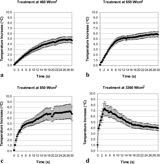
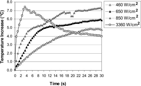
Temperature behavior at the tissue-air interface in the post-focal region followed different trends depending on the levels of applied HIFU intensities. At intensities of 460–850 W∕cm2, when no bubbles were detected during the majority of treatments, the temperature at the interface increased throughout the treatment [Figs. 4a, 4b, 4c]. However, at the highest intensity of 3360 W∕cm2, when bubbles were observed immediately after the start of the treatment, the temperature started to rise initially but reached a peak relatively early (at 3.5 s) in the treatment (coinciding with early formation of bubbles) and then dropped for the rest of the treatment [Fig. 4d]. The temperature increase (relative to the baseline temperature) was lower at the end of the treatment at 3360 W∕cm2 than temperature increases achieved at the end of the treatments at 460–850 W∕cm2 (Table 1). Figure 5 provides direct comparison of the thermal behavior at the tissue-air interface at different intensity levels. All temperatures measured during in-vitro experiments were in the range of 17–33 °C.
Figure 4.
Temperature at the tissue-air interface in the post-focal region as a function of HIFU exposure time for in-vitro treatments at: (a) 460 W∕cm2 (n=11), (b) 650 W∕cm2 (n=8), (c) 850 W∕cm2 (n=9), and (d) 3360 W∕cm2 (n=9). Data are represented as mean±standard error of the mean.
Table 1.
Temperature increase (relative to pre-treatment temperature) after 30 s of HIFU exposure at different ultrasound intensities. Data are given as mean±standard deviation. Temperatures that were statistically different (p-value of less than 0.05) from the temperature at the highest intensity are shown with an asterisk.
| In-situ intensity (W∕cm2) | Temperature increase at the end of HIFU treatment (°C) | |
|---|---|---|
| In-vitro | 460 | 4.8±1.9(n=11) |
| 650 | 5.9±1.4*(n=8) | |
| 850 | 7.2±3.9*(n=9) | |
| 3360 | 4.0±1.4(n=9) | |
| In-vivo: Liver | 800 | 17.0±4.4(n=2) |
| 3500 | 11.0±3.3(n=2) | |
| In-vivo: Muscle | 1200 | 11.1±6.0*(n=6) |
| 3500 | 4.0±1.4(n=5) |
Figure 5.
Comparison of temperature increases at the in-vitro tissue-air interface at different HIFU intensities.
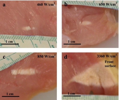
Table 2 shows the incidence of hyperecho formation at the location of HIFU focus in ultrasound images and the time at which hyperecho occurred at each intensity. At the lowest intensity of 460 W∕cm2, hyperecho was not observed (except in one case at the end of treatment), indicating absence of bubbles at the HIFU focus, and formation of purely thermal lesions. At the intensities of 650–850 W∕cm2, hyperecho was observed in less than 38% of cases and started relatively late in the treatment, at 21 s on average for the 650 W∕cm2 treatment and at 17 s on average for the 850 W∕cm2 treatment. At the highest intensity of 3360 W∕cm2, hyperecho formed immediately after the start of HIFU application in all cases, indicating the presence of bubbles at the HIFU focus throughout the treatment and formation of lesions due to both thermal and cavitation effects.19, 20, 21 The gross appearance of HIFU lesions (Fig. 6) confirmed diagnostic ultrasound observations. At 460 W∕cm2, the lesions were ellipsoidal in shape and formed at the HIFU focus [Fig. 6a], thus having characteristics of purely thermal lesions. At 650–850 W∕cm2, lesions were still thermal in appearance [Figs. 6b, 6c], which was in agreement with late or no formation of hyperecho. At the highest intensity of 3360 W∕cm2, the lesions shifted to the pre-focal region and were tadpole in shape [Fig. 6d], which indicated the presence of bubbles at the HIFU focus19, 23 and was in agreement with the observed immediate formation of hyperecho.
Table 2.
Hyperecho formation at different ultrasound intensities. The overall HIFU treatment time was 30 s.
| In-situ intensity (W∕cm2) | Energy dose (kJ∕cm2) | Number of treatments | Number of cases with observed hyperecho | Time when hyperecho started (s) |
|---|---|---|---|---|
| 460 | 13.8 | 11 | 1 | 27 |
| 650 | 19.5 | 8 | 3 | 21±10 |
| 850 | 25.5 | 9 | 3 | 17±3 |
| 3360 | 100.8 | 9 | 9 | 0 |
Figure 6.
Gross appearance of the lesions produced in the turkey breast in-vitro at HIFU intensities of: (a) 460 W∕cm2, (b) 650 W∕cm2, (c) 850 W∕cm2, and (d) 3360 W∕cm2. At the highest intensity, the lesions grew to the front surface from which HIFU energy was applied. The HIFU transducer was located on the right-hand side of the images in all cases.
In-vivo
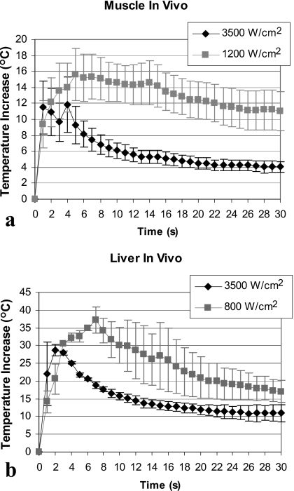
Our in-vivo results confirmed in-vitro observations. Figure 7 shows temperature measurements in-vivo at the muscle-air (a) and liver-air (b) interfaces located in the post-focal region. Measured temperatures were in the range of 33 °C (baseline temperature) to 74 °C. For muscle, the maximal temperature increase was on average 3.8 °C higher for the low intensity treatment as compared to the high intensity treatment (15.6±8.0 °C at 1200 W∕cm2 versus. 11.8±7.8 °C at 3500 W∕cm2) [Fig. 7a]. Similar results were obtained in the liver where the maximal temperature increase was 37.2±5.1 °C at 800 W∕cm2 and 28.7±2.4 °C at 3500 W∕cm2 [Fig. 7b]. Temperatures at the end of the treatment were higher for the low intensity treatments as compared to the high intensity treatments for both liver and muscle (Table 1).
Figure 7.
Temperature at the in-vivo tissue-air interface in the post-focal region at the low and high HIFU intensity. (a) Treatment of thigh muscle (n=6 at 1200 W∕cm2; n=5 at 3500 W∕cm2). Interface was located at 2 cm from the HIFU focus. (b) Liver treatment (n=2 for each intensity). Interface was located at approximately 1 cm from the HIFU focus. Data are represented as mean±standard error of the mean.
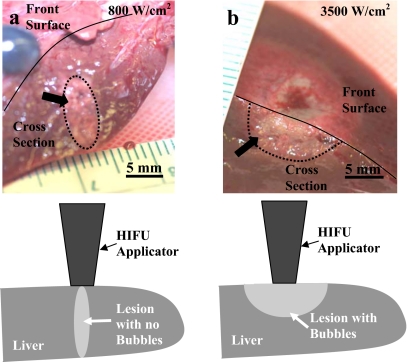
In-vivo lesions produced at the low intensity were ellipsoidal in shape [Fig. 8a] in both liver and muscle and formed around the HIFU focus, indicating the absence of bubbles at the focus. The lesions produced at the high intensity were tadpole or half-spherical in shape and were located in the pre-focal region extending to the front surface (where HIFU was applied from), indicating the presence of bubbles at the focus [Fig. 8b].
Figure 8.
Gross appearance of HIFU lesions (arrows) produced in the liver in-vivo at (a) 800 W∕cm2 and (b) 3500 W∕cm2. Dotted lines are used to outline the HIFU lesions at tissue depth. Solid lines are used to show the border between the liver cross section and the front surface of the liver (that was in contact with the HIFU transducer). Drawings show position of the HIFU transducer relative to the lesion location.
DISCUSSION
Safety of HIFU treatments is becoming a topic of increased interest, due to a recent transition of HIFU technology into clinical practice.3, 26, 27, 28 For example, the United States Food and Drug Administration (FDA) has raised a concern about damage that may occur in healthy tissues located near a bony structure in the post-focal HIFU region.10 This type of damage occurred previously during MRI-guided HIFU treatment of uterine fibroids in which the sciatic nerve was injured, resulting in pain in the patient leg.14 Temperature at the nerve site was not reported for this treatment, but based on previous animal studies, the exposure to 47 °C for less than a minute can result in transient nerve injury, while the exposure to 51 °C for 1.5 min can cause permanent nerve damage.29 The HIFU protocol for uterine fibroid treatment was subsequently changed to limit the treatment to the fibroid regions that are more than 4 cm away from major nerves located in proximity to bone,14 which would reduce the number of patients eligible for the treatment. As an alternative, healthy tissues located post-focally may be protected by choosing HIFU parameters such that little or no energy is propagated beyond the focus. We have shown in this manuscript that production of bubbles at the HIFU focus may provide a way to protect sensitive structures located post-focally.
Bubbles formed at the HIFU focus can be the result of both cavitation (i.e., ultrasound-induced oscillations of microbubbles grown from gaseous nuclei in the tissue30, 31, 32), and boiling due to the high temperatures that can be reached within seconds at the HIFU focus.32 Gas bubbles (due to cavitation) of few micrometers in size can form a scattering and∕or absorption barrier for HIFU propagation into the post-focal region, especially if resonant bubbles are present at the focus.15 Furthermore, vapor bubbles created by boiling can grow rapidly to a large size on the order of millimeters, effectively reflecting ultrasound from the HIFU focal region.16 Therefore, both gas and vapor bubbles can be utilized to shield the tissues beyond HIFU focus.
Historically, the presence of bubbles at the HIFU focus was avoided since it results in the pre-focal lesion formation which can increase the complexity of treatment planning.16, 19, 33 However, recent studies have shown that the presence of bubbles at the focus may be advantageous in HIFU therapy, because it leads to the formation of lesions that are 2–3 times larger as compared to the lesions formed with no bubbles.34, 35, 36 The increase in the lesion size is believed to occur due to a rapid rise in temperature at the HIFU focus due to bubble-enhanced heating.20, 32, 37, 38 Formation of large HIFU lesions can lead to faster treatments, needed in coagulation of large tumors.1, 4 However, careful characterization of the size, shape, and location of the lesions formed in the presence of bubbles is necessary before such lesions could be applied in clinical practice. Although more complex than purely thermal lesions, the lesions produced in the presence of bubbles have predictable location (in the pre-focal HIFU region), and shape (tadpole or spherical).23, 38, 39
The presence of bubbles at the HIFU focus can be observed by hyperecho formation in B-mode ultrasound images, as confirmed with both cavitation detection (active and passive)20, 21 and gross observations of the HIFU lesions.19, 23, 40 In our experiments, hyperecho formed immediately after the start of HIFU treatment at the highest intensity, and the temperature at the interface started to decrease several seconds after hyperecho was first observed. Therefore, it appeared that some time was needed for bubbles at the focus to reach the concentration and∕or overall bubble cloud size that was sufficiently large to impede the propagation of the HIFU beam. At lower intensities, hyperecho appeared later in the treatment if at all. This hyperecho behavior indicated a small number and∕or size of bubbles at the HIFU focus, which was in agreement with the fact that no decrease in temperature was observed for these treatments, and also with the gross observations showing the formation of purely thermal lesions.19
The following equation (based on experiments and simulations) has been used to estimate the exposure time t which will result in tissue damage at a temperature T higher than 43 °C, where t43 is the equivalent number of minutes at 43 °C:41
The damage to soft tissues was shown previously to occur at HIFU thermal doses greater than 31.2 equivalent minutes at 43.0 °C,42 or within 1 s at 60 °C.15, 40 Based on these general guidelines, the temperature increases achieved at the tissue-air interface in our liver treatments were sufficiently high to produce thermal damage within seconds, while the damage would be produced only after several minutes in our muscle treatments.41 Previous studies have also shown a clinically significant temperature increase at tissue interfaces with air.8, 12 For example, up to four times temperature increase was observed at the skin-air interface located in the transducer far-field, resulting in hot spots on the skin.8
Both MRI and ultrasound are currently used for guidance of HIFU therapy.2, 7, 14, 26 During MRI-guided treatment, care is usually taken that no bubbles are produced,43 since MRI thermometry is prone to artifacts if tissue changes other than thermal changes are present in the region of interest.44 The formation of bubbles during lesion production is desired during ultrasound-guided HIFU therapy, since these lesions can be correlated with hyperechoic regions in ultrasound images.21, 45 Hyperecho formation can be used for treatment monitoring,7, 46 as well as pre-treatment targeting (to establish whether HIFU focus is indeed located at the treatment site). Hyperecho was shown to form even at very short HIFU exposures (of 30 ms) with no or minimal concomitant tissue damage.20
In summary, the formation of HIFU lesions in the presence of bubbles may have a number of advantages. First, larger lesions can be produced resulting in faster treatment times.35 Second, these lesions can be observed in realtime as a hyperechoic region in ultrasound images, allowing treatment monitoring and guidance.7 Finally, our current report shows that the formation of bubbles at the HIFU focus may protect the tissues near interfaces in the post-focal regions from potential thermal damage. There is still much to learn regarding the optimization of the lesions formed in the presence of bubbles to achieve safe and efficient treatments. For example, further work is needed in characterization of the lesion position and size at different HIFU parameters, optimization of lesion to lesion interaction during treatments of large tissue volumes, and correlation of the hyperecho observed in ultrasound images with the actual lesion size.
ACKNOWLEDGMENTS
This work was supported by National Institutes of Health grant R01 EB00292, and National Space Biomedical Research Institute through NASA NCC 9-58.
References
- Kennedy J. E., ter Haar G. R., and Cranston D., “High intensity focused ultrasound: surgery of the future?,” Br. J. Radiol. 10.1259/bjr/17150274 76, 590–599 (2003). [DOI] [PubMed] [Google Scholar]
- McDannold N., Tempany C. M., Fennessy F. M., So M. J., Rybicki F. J., Stewart E. A., Jolesz F. A., and Hynynen K., “Uterine leiomyomas: MR imaging-based thermometry and thermal dosimetry during focused ultrasound thermal ablation,” Radiology 10.1148/radiol.2401050717 240, 263–272 (2006). [DOI] [PMC free article] [PubMed] [Google Scholar]
- Rebillard X., Gelet A., Davin J. L., Soulie M., Prapotnich D., Cathelineau X., Rozet F., and Vallancien G., “Transrectal high-intensity focused ultrasound in the treatment of localized prostate cancer,” J. Endourol 19, 693–701 (2005). [DOI] [PubMed] [Google Scholar]
- Tempany C. M., Stewart E. A., McDannold N., Quade N. B. J., Jolesz F. A., and Hynynen K., “MR imaging-guided focused ultrasound surgery of uterine leiomyomas: a feasibility study,” Radiology 10.1148/radiol.2271020395 226, 897–905 (2003). [DOI] [PubMed] [Google Scholar]
- Wu F., “Extracorporeal high intensity focused ultrasound in the treatment of patients with solid malignancy,” Minimally Invasive Ther. Allied Technol. 15, 26–35 (2006). [DOI] [PubMed] [Google Scholar]
- ter Haar G., Sinnett D., and Rivens I., “High intensity focused ultrasound—a surgical technique for the treatment of discrete liver tumours,” Phys. Med. Biol. 10.1088/0031-9155/34/11/021 34, 1743–1750 (1989). [DOI] [PubMed] [Google Scholar]
- Vaezy S., Andrew M., Kaczkowski P., and Crum L., “Image-guided acoustic therapy,” Annu. Rev. Biomed. Eng. 10.1146/annurev.bioeng.3.1.3753, 375–390 (2001). [DOI] [PubMed] [Google Scholar]
- Hynynen K., “Hot spots created at skin-air interfaces during ultrasound hyperthermia,” Int. J. Hyperthermia 6, 1005–1012 (1990). [DOI] [PubMed] [Google Scholar]
- Myers M. R., “Transient temperature rise due to ultrasound absorption at a bone/soft-tissue interface,” J. Acoust. Soc. Am. 10.1121/1.1707091 115, 2887–2891 (2004). [DOI] [PubMed] [Google Scholar]
- Harris G. R., “The FDA perspective on pre-clinical testing for high intensity focused ultrasound devices,” AIP Conf. Proc. 10.1063/1.2205543 829, 595–598 (2006). [DOI] [Google Scholar]
- Fennessy F. M. and Tempany C. M., “MRI-guided focused ultrasound surgery of uterine leiomyomas,” Acad. Radiol. 12, 1158–1166 (2005). [DOI] [PubMed] [Google Scholar]
- Damianou C., “MRI monitoring of the effect of tissue interfaces in the penetration of high intensity focused ultrasound in kidney in vivo,” Ultrasound Med. Biol. 30, 1209–1215 (2004). [DOI] [PubMed] [Google Scholar]
- Christensen D., Ultrasonic Bioinstrumentation (Wiley, New York, 1988). [Google Scholar]
- Hindley J., Gedroyc W. M., Regan L., Stewart E., Tempany C., Hynynen K., McDannold N., Inbar Y., Itzchak Y., Rabinovici J., Kim H. S., Geschwind J. F., Hesley G., Gostout B., Ehrenstein T., Hengst S., Sklair-Levy M., Shushan A., and Jolesz F., “MRI guidance of focused ultrasound therapy of uterine fibroids: early results,” AJR, Am. J. Roentgenol. 183, 1713–1719 (2004). [DOI] [PubMed] [Google Scholar]
- Clarke R. L. and ter Haar G. R., “Temperature rise recorded during lesion formation by high-intensity focused ultrasound,” Ultrasound Med. Biol. 10.1016/S0301-5629(96)00198-6 23, 299–306 (1997). [DOI] [PubMed] [Google Scholar]
- Watkin N. A., ter Haar G. R., and Rivens I., “The intensity dependence of the site of maximal energy deposition in focused ultrasound surgery,” Ultrasound Med. Biol. 10.1016/0301-5629(95)02062-4 22, 483–491 (1996). [DOI] [PubMed] [Google Scholar]
- Atchley A. and Crum L. A., “Acoustic Cavitation and Bubble Dynamics,” in Ultrasound: Its Chemical, Physical and Biological Effects, edited by Suslick K. S. (VCH Publishers, New York, 1988), pp. 1–64. [Google Scholar]
- Vaezy S., Shi X., Martin X. R. W., Chi E., Nelson P. I., Bailey M. R., and Crum L. A., “Real-time visualization of high-intensity focused ultrasound treatment using ultrasound imaging,” Ultrasound Med. Biol. 10.1016/S0301-5629(00)00279-9 27, 33–42 (2001). [DOI] [PubMed] [Google Scholar]
- Bailey M. R., Couret L. N., Sapozhnikov O. A., Khokhlova V. A., ter Haar G., Vaezy S., Shi X., Martin R., and Crum L. A., “Use of overpressure to assess the role of bubbles in focused ultrasound lesion shape in vitro,” Ultrasound Med. Biol. 10.1016/S0301-5629(01)00342-8 27, 695–708 (2001). [DOI] [PubMed] [Google Scholar]
- Rabkin B., Zderic V., Crum L. A., and Vaezy S., “Biological and physical mechanisms of HIFU-induced hyperecho in ultrasound images,” Ultrasound Med. Biol. 32, 1721–1729 (2006). [DOI] [PubMed] [Google Scholar]
- Rabkin B. A., Zderic V., and Vaezy S., “Hyperecho in ultrasound images of HIFU therapy: involvement of cavitation,” Ultrasound Med. Biol. 10.1016/j.ultrasmedbio.2005.03.015 31, 947–956 (2005). [DOI] [PubMed] [Google Scholar]
- Held R. T., Zderic V., Nguyen T. N., and Vaezy S., “Annular phased-array high-intensity focused ultrasound device for image-guided therapy of uterine fibroids,” IEEE Trans. Ultrason. Ferroelectr. Freq. Control 53, 335–348 (2006). [DOI] [PubMed] [Google Scholar]
- Lafon C., Zderic V., Noble M. L., Yuen J. C., Kaczkowski P. J., Sapozhnikov O. A., Chavrier F., Crum L. A., and Vaezy S., “Gel phantom for use in high-intensity focused ultrasound dosimetry,” Ultrasound Med. Biol. 10.1016/j.ultrasmedbio.2005.06.004 31, 1383–1389 (2005). [DOI] [PubMed] [Google Scholar]
- Zderic V., Brayman A. A., Sharar S. R., Crum L. A., and Vaezy S., “Microbubble-enhanced hemorrhage control using high intensity focused ultrasound,” Ultrasonics 40, 113–120 (2006). [DOI] [PubMed] [Google Scholar]
- Martin R. W., Vaezy S., Proctor A., Myntti T., Lee J. B., and Crum L. A., “Water-cooled, high-intensity ultrasound surgical applicators with frequency tracking,” IEEE Trans. Ultrason. Ferroelectr. Freq. Control 50, 1305–1317 (2003). [DOI] [PubMed] [Google Scholar]
- Illing R. O., Kennedy J. E., Wu F., ter Haar G. R., Protheroe A. S., Friend P. J., Gleeson F. V., Cranston D. W., Phillips R. R., and Middleton M. R., “The safety and feasibility of extracorporeal high-intensity focused ultrasound (HIFU) for the treatment of liver and kidney tumours in a Western population,” Br. J. Cancer 10.1038/sj.bjc.6602803 93, 890–895 (2005). [DOI] [PMC free article] [PubMed] [Google Scholar]
- Rabinovici J., Inbar Y., Eylon S. C., Schiff E., Hananel A., and Freundlich D., “Pregnancy and live birth after focused ultrasound surgery for symptomatic focal adenomyosis: a case report,” Hum. Reprod. 21, 1255–1259 (2006). [DOI] [PubMed] [Google Scholar]
- Wu F., Wang Z. B., Lu P., Xu Z. L., Chen W. Z., Zhu H., and Jin C. B., “Activated anti-tumor immunity in cancer patients after high intensity focused ultrasound ablation,” Ultrasound Med. Biol. 10.1016/j.ultrasmedbio.2004.08.003 30, 1217–1222 (2004). [DOI] [PubMed] [Google Scholar]
- Bunch T. J., Bruce G. K., Mahapatra S., Johnson S. B., Miller D. V., Sarabanda A. V., Milton M. A., and Packer D. L., “Mechanisms of phrenic nerve injury during radiofrequency ablation at the pulmonary vein orifice,” J. Cardiovasc. Electrophysiol. 16, 1318–1325 (2005). [DOI] [PubMed] [Google Scholar]
- Crum L. A. and Hansen G. M., “Growth of air bubbles in tissue by rectified diffusion,” Phys. Med. Biol. 10.1088/0031-9155/27/3/008 27, 413–417 (1982). [DOI] [PubMed] [Google Scholar]
- Hill C. R. and ter Haar G. R., “Review article: high intensity focused ultrasound—potential for cancer treatment,” Br. J. Radiol. 68, 1296–1303 (1995). [DOI] [PubMed] [Google Scholar]
- Holt R. G. and Roy R. A., “Measurements of bubble-enhanced heating from focused, MHz-frequency ultrasound in a tissue-mimicking material,” Ultrasound Med. Biol. 10.1016/S0301-5629(01)00438-0 27, 1399–1412 (2001). [DOI] [PubMed] [Google Scholar]
- Malcolm A. L. and ter Haar G. R., “Ablation of tissue volumes using high intensity focused ultrasound,” Ultrasound Med. Biol. 10.1016/0301-5629(96)00020-8 22, 659–669 (1996). [DOI] [PubMed] [Google Scholar]
- Kaneko Y., Maruyama T., Takegami K., Watanabe T., Mitsui H., Hanajiri K., Nagawa H., and Matsumoto Y., “Use of a microbubble agent to increase the effects of high intensity focused ultrasound on liver tissue,” Eur. Radiol. 15, 1415–1420 (2005). [DOI] [PubMed] [Google Scholar]
- Sokka S. D., King R., and Hynynen K., “MRI-guided gas bubble enhanced ultrasound heating in in vivo rabbit thigh,” Phys. Med. Biol. 10.1088/0031-9155/48/2/306 48, 223–241 (2003). [DOI] [PubMed] [Google Scholar]
- Yu T., Fan X., Xiong S., Hu K., and Wang Z., “Microbubbles assist goat liver ablation by high intensity focused ultrasound,” Eur. Radiol. 16, 1557–1563 (2006). [DOI] [PubMed] [Google Scholar]
- Hynynen K., “The threshold for thermally significant cavitation in dog’s thigh muscle in vivo,” Ultrasound Med. Biol. 10.1016/0301-5629(91)90123-E 17, 157–169 (1991). [DOI] [PubMed] [Google Scholar]
- Melodelima D., Chapelon J. Y., Theillere Y., and Cathignol D., “Combination of thermal and cavitation effects to generate deep lesions with an endocavitary applicator using a plane transducer: ex vivo studies,” Ultrasound Med. Biol. 10.1016/j.ultrasmedbio.2003.09.005 30, 103–111 (2004). [DOI] [PubMed] [Google Scholar]
- Curiel L., Chavrier F., Gignoux B., Pichardo S., Chesnais S., and Chapelon J. Y., “Experimental evaluation of lesion prediction modelling in the presence of cavitation bubbles: intended for high-intensity focused ultrasound prostate treatment,” Med. Biol. Eng. Comput. 10.1007/BF02351010 42, 44–54 (2004). [DOI] [PubMed] [Google Scholar]
- ter Haar G., “Ultrasound focal beam surgery,” Ultrasound Med. Biol. 10.1016/0301-5629(95)02010-1 21, 1089–1100 (1995). [DOI] [PubMed] [Google Scholar]
- Sapareto S. A. and Dewey W. C., “Thermal dose determination in cancer therapy,” Int. J. Radiat. Oncol., Biol., Phys. 10, 787–800 (1984). [DOI] [PubMed] [Google Scholar]
- McDannold N. J., King R. L., Jolesz F. A., and Hynynen K., “Usefulness of MR imaging-derived thermometry and dosimetry in determining the threshold for tissue damage induced by thermal surgery in rabbits,” Radiology 216, 517–523 (2000). [DOI] [PubMed] [Google Scholar]
- Hynynen K., Freund W. R., Cline H. E., Chung A. H., Watkins R. D., Vetro J. P., Jolesz F. A., “A clinical, noninvasive, MR imaging-monitored ultrasound surgery method,” Radiographics 16, 185–195 (1996). [DOI] [PubMed] [Google Scholar]
- McDannold N., Hynynen K., and Jolesz F., “MRI monitoring of the thermal ablation of tissue: effects of long exposure times,” J. Magn. Reson Imaging 13, 421–427 (2001). [DOI] [PubMed] [Google Scholar]
- Yu T. and Xu C., “Hyperecho as the indicator of tissue necrosis during microbubble-assisted high intensity focused ultrasound: sensitivity, specificity and predictive value,” Ultrasound Med. Biol. 34, 1343–1347 (2008). [DOI] [PubMed] [Google Scholar]
- Kennedy J. E., Wu F., and ter Haar G. R., “High-intensity focused ultrasound for the treatment of liver tumours,” Ultrasonics 10.1016/j.ultras.2004.01.089 42, 931–935 (2004). [DOI] [PubMed] [Google Scholar]


