Abstract
This study presents a two-laser alignment approach for facilitating the precise alignment of various imaging and measuring components with respect to the x-ray beam. The first laser constantly pointed to the output window of the source, in a direction parallel to the path along which the components are placed. The second laser beam, originating from the opposite direction, was calibrated to coincide with the first laser beam. Thus, a visible indicator of the direction of the incident x-ray beam was established, and the various components could then be aligned conveniently and accurately with its help.
Keywords: x-ray imaging, alignment, laser-based positioning, spectral measurements
INTRODUCTION
The alignment between the radiation source, the subject, and the measuring and detecting devices is critical in x-ray imaging experiments and has been investigated in subject positioning and portable radiography,1, 2 as well as in the measurement of modulation transfer function (MTF),3, 4 focal spot size,5, 6 and x-ray spectra.6, 7, 8, 9 Several techniques for alignment using lasers and other methods have been devised and reported in literature, such as the combination of a laser projector and reflectors to indicate the correct relative position between the subject, the detector, and the x-ray beam,1, 2, 3, 5 the combination of laser positioning and pinhole focal-spot radiography to provide precise alignment,4, 9 the use of a single laser that points to the focal spot position to help the alignment of an x-ray spectrometer,8 and the use of multi-pinhole plate and telescope-based observation in determining the collimator position in spectral measurements.6 In this study, a new alignment approach is reported, which differs from the other methods in that it provides two coinciding laser beams pointing toward and away from the x-ray source, instead of using only one laser pointing toward the source. The advantage of this two laser configuration is that it provides a highly accurate method to form a visible indicator of the incident x-ray from both directions. Thus imaging components such as the pinhole collimators used in the spectral measurements can be aligned very intuitively and precisely through the help of the laser beams.
The alignment process is described in detail after a brief description of the target x-ray imaging system10, 11, 12, 13 on which the alignment approach was implemented. In addition, the adjustment of the coverage of the x-ray beam on the detector is also presented, as it is considered a critical part of the system tuning process because it ensures a relatively uniform x-ray field on the detector.
MATERIALS AND METHODS
Description of the imaging system
The imaging system utilized in this study employs a micro-focus x-ray source (UltraBright, Oxford Instruments, CA) and a computed radiography (CR) system (Regius 190, Konica Minolta, NJ) for image detection. The various imaging and measuring components of the system are mounted on a supporting optical rail on which their positions can be conveniently adjusted.
Standard opto-mechanic components were used to form the holding structures for the measurement devices, lasers, detectors, objects, and x-ray tube, due to their ability to produce flexible, accurate, and reproducible alignment and positioning for the imaging components. In addition, linear and rotational stages were also utilized to effectively and precisely control their horizontal, vertical, and angular positions.
The alignment procedure based on two laser positioning devices
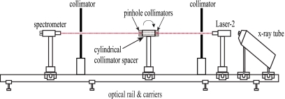
Precise alignment is essential in certain measurements and imaging tasks, as discussed in Sec. 1, although it often requires arduous efforts and is therefore very time consuming. In order to ease the difficulty and to improve the accuracy of the alignment tasks, two laser pointers were used to establish a visible indicator of the incident x-ray beam. The laser pointers were mounted at opposite ends of the supporting rail and positioned to face each other, as shown in Fig. 1. During the alignment process, the laser facing the x-ray source, hereafter referred to as Laser-1, was first calibrated to ensure that the laser beam constantly pointed towards the output window of the x-ray tube when the position of the laser was adjusted along the optical rail. This verified that the laser beam was parallel to the direction along which the components were positioned, which was the direction of the supporting optical rail in this study. The beam of Laser-1 thus indicated the position of the x-ray source with respect to the supporting rail and provided a baseline for the other laser to be calibrated.
Figure 1.
Schematic of the alignment process.
The laser at the opposite end of the rail, hereafter referred to as Laser-2, was then adjusted so that the beam coincided exactly with the beam from Laser-1. To verify this, two transparency films were placed a distance of approximately 20 cm apart within the path of the two laser beams. The congruence of the laser beams was confirmed when the laser dots on both sides of each transparency film were overlapping. To provide a numeric measure of the coincidence of the laser beams, another transparency film bearing a 10×10 cm2 grid with line spacing of 1 mm was also utilized. The transparency was fixed to the optical rail by a holder which could travel along the rail. While moving the transparency film along the rail, the position of the laser dots on the grid from both Laser-1 and Laser-2 were recorded individually and both determined to hold a constant position of [4.2 mm, 3.5 mm]. This correspondence of the laser positions thus verified that the laser beams were coinciding and parallel to the optical rail. Since the direction of the beam from Laser-2 was the same as that of the x-ray from the source, it provided an intuitive illustration of the incident x-ray. This preparation enabled the position of the object, detectors, and other devices to be aligned easily and accurately with the help of the two laser beams. It should be noted that although the two lasers employed in this study both generate red-colored lasers, the use of different colored lasers (red and green, for example) may make the alignment even more convenient.
Although Laser-2 is more convenient to use in the alignment process due to the direction of its beam, it must be removed from the path of the x ray to allow image acquisition and measurements. Laser-1, which is located at the opposite end of the supporting rail from the x-ray source, can maintain its position during the imaging and measurement processes, and thus facilitates reestablishing the alignment of Laser-2. Verifying that the two laser beams are parallel to the supporting optical rail is critical for this alignment process, as the laser beams function as the baseline for mounting and positioning other imaging and measuring components along the rail.
Laser alignment of collimators in spectral measurements
In spectral measurements, pinhole collimators are commonly used to limit the flux of the incident x ray arriving on the spectrometers.6, 8, 9 In the spectral experiments performed in this study, a CdTe detector (XR-100T-CdTe, Amptek Inc., Bedford, MA) was employed. Although the vendor of the spectrometer provided a collimator kit and detailed the implementation of a two-pinhole-collimator approach8 to aid the collimation process, the precise alignment of the collimators and input window of the CdTe detector with respect to the direction of the incident beam remains a difficult task. This is due to the fact that the pinhole collimators must be aligned concentrically with respect to each other, as well as the direction of the incident beam, in order to reduce the beam filtration resulting from the collimation. Using our two-laser alignment approach, this problem could be adequately solved. When the coinciding laser beam from both Laser-1 and Laser-2 is established as described in Sec. 2 B, the laser from Laser-2 could be utilized as a visible substitute for the incident x-ray beam in the spectral measurements. Thus when the laser from Laser-2 results in the brightest and roundest dot on the plane of the spectrometer’s input window after passing through the collimators, a good alignment is achieved. On the other hand, if the collimators were misaligned, no laser dot could be observed (see Fig. 2 for more details).
Figure 2.
The alignment of the collimators and the spectrometer with respect to the direction of the incident x-ray beam using the two-laser alignment approach. The beam from Laser-2 is utilized as the visible indicator of the incident x-ray beam. The pinhole collimators are then aligned concentrically with respect to each other, as well as the direction of the incident beam.
Adjustment of the x-ray beam coverage
In addition to aligning various components with respect to the x-ray source, it is necessary to adjust the placement of the x-ray source with respect to the detector position in order to ensure a relatively uniform x-ray field on the detector, which could help to reduce the background trends and∕or artifacts in acquired images. The prototype system employs a free-standing source that features an output window that is aligned at an angle with respect to the electron beam, the design of which has been reported to be helpful for producing a rounded micro focal spot. However, this design also introduces challenges into the alignment process. The angle between the x-ray tube and the supporting rail must be carefully adjusted in order to obtain relatively uniform beam coverage on the detectors, due to nonuniformities in the output x-ray field, such as the anode heel effect.
A series of images was acquired at different source to image distances (SIDs) for the adjustment of the tube angle. An initial image was acquired at an SID of 12 in. (≈30 cm) to illustrate the shape of the entire x-ray field, which is determined by the intrinsic collimation of the micro-focus x-ray source. From this image, a portion of the entire field with uniform pixel values was selected to be shifted to the center of the detector and aligned directly with respect to the pixel array by adjusting the tube. Through this process the detector could be covered by this uniform portion of the field at larger SIDs. During the adjustment, several images at a larger SID (91 cm) were acquired to guide the adjustment of the x-ray tube to achieve a uniform x-ray field. Then images taken at even larger SIDs (122, 127, and 132 cm) were obtained to further guide the tube adjustment and to determine the threshold SID, beyond which the entire detector (24 in. by 30 in.) is guaranteed to be covered by the uniform x-ray field. This threshold was determined to be 132 cm in our study and was thus utilized in our experiments to ensure a uniform x-ray field.
RESULTS
The accurate alignment of the tungsten pinhole collimators used in the x-ray spectral measurements (2 mm thick, with diameter of 100 and 200 μm, “Collimation Kit,” Amptek Inc., Bedford, MA) was verified through the use of x-ray images. The collimators were aligned with respect to the incident x-ray beam, separated by a 36 mm long brass collimator spacer with an aperture of 5 mm diameter, as shown in Fig. 2. Two images of the pinhole collimators were obtained with magnification of approximately 5, at 20 kV, 2 mA, and 400 s. With a good alignment, the pinhole x-ray image obtained was a rounded dot; as the angle of the collimators (Fig. 2) was tilted 0.1 deg away from the good position, the pinhole dot shrank and its shape was blurred; as the angle was tilted further (greater than 0.3 deg), the dot disappeared.
To further illustrate the advantage of using the two laser alignment approach, an example application of spectral measurements is provided. X-ray spectra were measured at 40 kV, 0.5 mA, 400 s with a Mo-Be target-window combination. The placement of the spectrometer and collimators is shown in Fig. 2, and the distance from the source to the spectrometer was approximately 6 ft (183 cm).
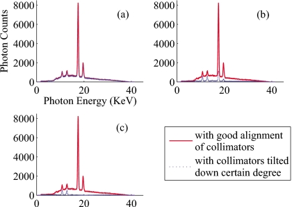
The influence of misalignment of the pinhole collimators can be observed through the photon rate received by the spectrometer, as well as the shape of the resultant spectra. With the collimators in good alignment with respect to the incident x-ray beam, the photon rate measured by the spectrometer was 1030 photon∕s. However, with a misalignment of approximately 0.1, 0.2, and 0.3 deg away from the good alignment position, the photon rate reduced to 947, 222, and 103 photon∕s, respectively. This is illustrated in Fig. 3, which compares the good alignment spectrum separately with each degree of misalignment. As the tilt angle was increased, the magnitude and shape of the spectrum obtained with misalignment gradually deviated from that acquired with good alignment. The difference in the magnitude is due to the decreasing photon rates in the spectral measurements, and the difference in the shape of the spectra is probably caused by the beam filtration from the collimators, which blocked and filtered the primary x-ray beam rather than only allowing a limited portion of photons in the primary beam to pass through their apertures.
Figure 3.
X-ray spectrum measured with a CdTe detector at a good alignment position of the two tungsten collimator disks compared separately with the spectrum obtained with a collimator position 0.1 (a), 0.2 (b), and 0.3 (c) deg tilted away from the good alignment position, respectively. The spectra were measured at 40 kV with a Mo-Be target-window combination.
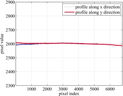
Profiles on both x direction (the short side of the image) and y direction (the long side of the image) of the x-ray field after the adjustment of the tube are shown in Fig. 4. The image was taken at 40 kV, 0.5 mA, and 12 s, with an SID of 52 in. (132 cm), which was the threshold SID beyond which the entire detector could be covered by the uniform x-ray field, as mentioned in Sec. 2D. The profiles were measured as the mean of 1000 rows on the x direction and 1000 columns on the y direction at the center of the image. The maximum and minimum value of the measured profile on x direction are 2581 and 2608, respectively; the maximum and minimum value of the profile on y direction are 2589 and 2607, respectively.
Figure 4.
Profile of the x-ray field on the detector after the adjustment of the placement of x-ray tube. The image was taken at 40 kV, 0.5 mA, 12 s and with SID of 52 in. (132 cm).
DISCUSSIONS AND CONCLUSION
This paper reports a convenient two-laser alignment approach by which the positioning of the imaging and measuring components with respect to the x-ray beam can be easily achieved. The first laser was positioned a distance from the source with its beam adjusted to constantly point towards the output window of the x-ray tube and parallel to the direction along which the components are placed. Then the second laser was calibrated to ensure that its beam coincided with the beam from the first laser. After that, a visible indicator of the direction of the x-ray beam was established and the imaging components could thus be aligned conveniently and accurately. One of the advantages of the proposed alignment approach was illustrated in x-ray spectral measurements in which the pinhole collimators and the spectrometer could be conveniently and precisely aligned with respect to the direction of incident x-ray beam based on the laser beam.
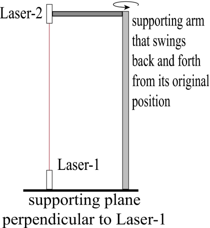
The proposed alignment approach could also be adapted to clinical settings under which the x-ray tube beam exit window is not visible, although this would introduce some additional steps for our alignment approach to be applied to clinical systems. For example, as indicated by the literature,4, 9 pinhole focal-spot radiography could be used to determine the position of the focal spot, and the pinhole placed in front of the tube could thus be used as an indicator of the focal spot position. In addition, the optical rail and opto-mechanic components may not be applicable in a clinical setting, although they play an important role as the base for accurate and reproducible alignment in this experimental environment. However, the idea of this precise two-laser alignment approach would still apply in such settings. For example, a device as shown in Fig. 5 could be constructed and utilized, which consists of a supporting plane that is perpendicular to the first laser beam and a supporting arm for moving the second laser. The arm would permit the laser to swing back and forth from the alignment position where the two beams are coinciding to an alternate location allowing Laser-1 to point to the focal spot position. For most clinical systems, the x-ray beam is designed so that the central x-ray is perpendicular to the detector, thus the device in Fig. 5 would provide an acceptable means for precise alignment utilizing the coincident laser beams.
Figure 5.
Schematic of a device for applying the proposed alignment approach in a clinical setting.
In conclusion, the reported alignment process is suitable for facilitating accurate image acquisition and measurement, as it provides a precise and simple method for ensuring the alignment of various components with respect to the direction of incident x-ray beam.
ACKNOWLEDGMENTS
The research is supported in part by grants from the National Institute of Health (RO1 CA104773). The authors would also like to acknowledge the support of the University of Oklahoma Office of the Vice President for Research, as well as the Charles and Jean Smith Chair endowment fund.
References
- Brezovich I. A. and Jordan S., “A device for precision positioning and alignment of room lasers to diminish their contribution to patient setup errors,” J. Appl. Clin. Med. Phys. 8(4), 45–53 (2007). [DOI] [PMC free article] [PubMed] [Google Scholar]
- MacMahon H., Yasillo N. J., and Carlin M., “Laser alignment system for high-quality portable radiography,” Radiographics 12(1), 111–120 (1992). [DOI] [PubMed] [Google Scholar]
- Samei E., Flynn M. J., and Reimann D. A., “A method for measuring the presampled mtf of digital radiographic systems using an edge test device,” Med. Phys. 10.1118/1.598165 25(1), 102–113 (1998). [DOI] [PubMed] [Google Scholar]
- Droege R. T., “A megavoltage mtf measurement technique for metal screen-film detectors,” Med. Phys. 10.1118/1.594581 6(4), 272–279 (1979). [DOI] [PubMed] [Google Scholar]
- Kubota H., Ozaki Y., Matsumoto M., and Kanamori H., “Determination of x-ray tube focal spot position,” Med. Phys. 10.1118/1.597122 20(4), 1029–1031 (1993). [DOI] [PubMed] [Google Scholar]
- Nishizawa K., Maekoshi H., Kamiya Y., Kobayashi Y., Ohara K., and Sakuma S., “Alignment of x-ray tube focal spots for spectral measurement,” Med. Phys. 10.1118/1.595086 9(2), 284–287 (1982). [DOI] [PubMed] [Google Scholar]
- Epp E. R. and Weiss H., “Experimental study of the photon energy spectrum of primary diagnostic x-rays,” Phys. Med. Biol. 10.1088/0031-9155/11/2/302 11(2), 225–238 (1966). [DOI] [PubMed] [Google Scholar]
- Bottigli U., Golosio B., Masala G. L., Oliva P., Stumbo S., Delogu P., Fantacci M. E., Abbene L., Fauci F., and Raso G., “Comparison of two portable solid state detectors with an improved collimation and alignment device for mammographic x-ray spectroscopy,” Med. Phys. 10.1118/1.2229431 33(9), 3469–3477 (2006). [DOI] [PubMed] [Google Scholar]
- Miyajima S., Imagawa K., and Matsumoto M., “An alignment method for mammographic X-ray spectroscopy under clinical conditions,” Br. J. Radiol. 75(897), 763–766 (2002). [DOI] [PubMed] [Google Scholar]
- Meng F. B., Yan A. M., Zhou G., Wu X. Z., and Liu H., “Development of a dual-detector x-ray imaging system for phase retrieval study,” Nucl. Instrum. Methods Phys. Res. B 254(2), 300–306 (2007). [Google Scholar]
- Wu X. and Liu H., “A dual detector approach for x-ray attenuation and phase imaging,” J. X-Ray Sci. Technol. 12(1), 35–42 (2004). [Google Scholar]
- Liu H., Zhang D., and Wu X., “Development of a dual detector phase x-ray imaging system: design considerations,” Proc. IEEE Southwest Symp. on Image Analysis and Interpretation (SSIAI) (2008), pp. 193–196.
- Zhang D., Rong J., Chu R., Wu X. Z., and Liu H., “Imaging characteristics of a high resolution computed radiography system,” J. X-Ray Sci. Technol. 14(4), 273–282 (2006). [Google Scholar]


