Abstract
Electrospun nanocomposite scaffolds were fabricated by encapsulating multi-walled carbon nanotubes (MWNT) in poly (lactic acid) (PLA) nanofibers. Scanning electron microscopy (SEM) confirmed the fabrication of nanofibers, and transmission electron microscopy identified the alignment and dispersion of MWNT along the axis of the fibers. Tensile testing showed an increase in the tensile modulus for a MWNT loading of 0.25 wt% compared with electrospun nanofibrous mats without MWNT reinforcement. Conductivity measurements indicated that the confined geometry of the fibrous system requires only minute doping to obtain significant enhancements at 0.32 wt%. Adipose-derived human mesenchymal stem cells (hMSCs) were seeded on electrospun scaffolds containing 1 wt% MWNT and 0 wt% MWNT, to determine the efficacy of the scaffolds for cell growth, and the effect of MWNT on hMSC viability and proliferation over two weeks in culture. Staining for live and dead cells and DNA quantification indicated that the hMSCs were alive and proliferating through day 14. SEM images of hMSCs at 14 days showed morphological differences, with hMSCs on PLA well spread and hMSCs on PLA with 1% MWNT closely packed and longitudinally aligned.
Keywords: adipose-derived human mesenchymal stem cells, multi-walled carbon nanotubes, bone tissue engineering, poly (lactic acid), electrospinning, nanocomposites
Introduction
Mesenchymal stem cells play a significant role in the advancement of regenerative medicine for tissue and organ replacement (Pittenger et al 1999; Andrews et al 2005). These cells are found in adult tissues including bone and adipose tissue, as reservoirs of reparative cells, ready to populate an area and differentiate in response to signaling from wounds or diseases (Habib et al 2005; Battler et al 2006). At present, mesenchymal stem cells are on the forefront of tissue engineering research due to their availability from various source tissues and their multilineage potential (Habib et al 2005). One critical research focus is the development of scaffolds with properties and functionality that mimic the natural extracellular matrix on a similar size scale.
Scaffold materials play an important role in directing tissue growth and offer opportunities to manipulate and control stem cell behavior (Elisseeff et al 2006). Scaffolds for tissue engineering have been evolving through creation of preferred morphologies and specifically tailored physical properties. Scaffold materials for bone tissue engineering demand an internal structural design that is highly porous in nature and exhibits a large surface to volume ratio (Laurencin 2003; Lieberman et al 2005). These characteristics support the adhesion of cells, promote cellular ingrowth, and help regulate delivery of nutrients and removal of wastes. Scaffolds for tissue repair should have good biocompatibility, be biodegradable, and capable of interacting with cells of interest (Hench et al 2002). Polymeric matrices are promising candidates because they are able to meet these requirements for tissue scaffolds; however, they are not able to provide the specific cues needed for cellular growth and differentiation (Hutmacher 2000). Thus, polymer composite scaffolds have gained more interest due to their enhanced physical properties and biocompatibility (Lee et al 2003; Ma 2004; Sharma et al 2004; MacDonald et al 2005; Zhao et al 2005; Li et al 2006). In particular, doping a polymer with a conducting material provides electrical conductivity to the scaffold, which may be important for facilitating cell migration, proliferation, and differentiation via electrical stimulation (Kotwal et al 2001; Supronowicz et al 2002; Pedrotty et al 2005). Incorporating a conductive scaffold with an applied electric field has led to increases in cellular proliferation, calcium deposition, and gene expression for osteogenesis (Supronowicz et al 2002; Heng et al 2004). Thus, this work will highlight the specific conductance obtained by doping a polymeric system with fractional weight percentages of multi-walled carbon nanotubes in a three dimensional matrix and the efficacy of this scaffold in culture with adipose-derived hMSCs.
In order to create scaffolds for tissue engineering, researchers have revisited the method of electrospinning (Pham et al 2006). Electrospinning is a process that yields a highly porous scaffold by producing fibers on the submicron scale (Formhals 1934), similar to the natural features of the extracellular matrix (Li et al 2006). During the electrospinning process, a polymer solution is fed through a capillary at a metered rate while an electric potential is applied. When this potential overcomes the surface tension of the polymer solution, a whipping instability is created that produces extremely small fibers that are collected on a grounded collector. Fiber formation occurs when the intrinsic properties of the solution and the processing parameters are optimized (Shenoy et al 2005; Pham et al 2006). Electrospinning is an advantageous process because it can produce three-dimensional scaffolds from various polymer systems using essentially the same method and technique. Numerous investigators have experimented with the use of electrospun poly (lactic acid) (PLA) as a tissue scaffold and biocompatible membrane due to its approved use in vivo and its mechanical and degradation properties being well understood (Zong et al 2002, 2005; Zeng et al 2003; Inai et al 2005; Tan et al 2005).
To produce composite scaffolds using this fabrication method, nanomaterials can be encapsulated in nanofibers during electrospinning. Zeng and colleagues (2003) demonstrated that drugs could be loaded into nanofibers by suspending them within a polymer solution. With the addition of any particle: anionic, cationic, or nonionic, the diameter size and distribution of the electrospun fibers can be significantly reduced, enabling a modification of the fiber diameter for specific applications. Composite nanofibers containing hydroxyapatite and growth factors have also been investigated (Li et al 2006). That study involved encapsulation of hydroxyapatite crystals with a diameter of 50 nm inside electrospun silk. The composite nanofibers had a positive impact by promoting osteogenic differentiation of bone marrow derived mesenchymal stem cells, as evidenced by mineralized tissue formation (Li et al 2006).
Recent studies have investigated the combination of MWNT with PLA (Chen et al 2005; Zhang et al 2006). Carbon nanotubes, discovered by Iijima (1991), possess tremendous properties by having a very large aspect ratio. Carbon nanotubes have a tensile strength approaching 1 TPa and electrical conductivity of 100 S/cm (Poncharal et al 1999). Chen and colleagues (2005) were able to graft oligomers of PLA to the surface of MWNT; however, the grafting was not uniform and left much of the MWNT surface bare. Zhang and colleagues (2006) prepared nanocomposite PLA/MWNT scaffolds by solution casting. This fabrication method left MWNT exposed on the surface but created uniform films with increased conductance. As these studies and others show, carbon nanotubes can provide three specific enhancements to fibrous tissue scaffolds: modified fiber size, electrical conductivity, and increased material properties (strength) in a lightweight material. In this study, we evaluate the biocompatibility of a nanocomposite scaffold comprised of MWNT embedded within PLA with the future goal of utilizing it with an electric field to promote osteogenesis of adipose-derived hMSCs.
Though carbon nanotubes have such promising physical properties, their use in biomedical applications, specifically tissue engineering, has been limited due to concerns of cytotoxicity. This issue has been investigated by various researchers with differing results depending on the purity of the carbon nanotubes and the method of production (Smart et al 2006). A collaborative study by Smart and colleagues (2006) noted that the main causes for possible toxicity were due to the surface area/volume ratio, retention time of carbon nanotubes within a tissue, and residual catalyst within the carbon nanotube (Smart et al 2006).
For this investigation, the primary goal is to encapsulate a high percentage of MWNT inside polymeric PLA nanofibers to increase the conductance and produce a conductive scaffold. Dispersion and alignment of carbon nanotubes in electrospun nanofibers has been shown in other polymer systems including poly(ethylene oxide) and poly (acrylonitrile); however, the level of interaction between the MWNT and polymer has not been investigated for biocompatibility or use as a tissue scaffold (Dror et al 2003; Gong et al 2005; Ayutsede et al 2006). In a previous study, we identified processing parameters for the creation of electrospun nanocomposites with MWNT and validated the integration of MWNT into polymer nanofibers. In this investigation our focus is to determine the efficacy of electrospun MWNT/PLA composite nanofibers as a tissue scaffold with adipose-derived hMSCs; and evaluate their effects on hMSC viability, proliferation, and orientation on the electrospun scaffold.
Materials and methods
Materials
Poly(L-D-lactic acid; PLA) with a molecular weight (Mw) of 250,000 g/mol was obtained from Sigma-Aldrich (St. Louis, MO). PLA was solubilized in chloroform and dimethyl formamide (DMF) (Sigma-Aldrich) at a ratio of 3:1, respectively. Multi-walled carbon nanotubes with a diameter of 15 ± 5 nm and length of 5–20 μm at 95% purity were obtained from Nano-Lab (Brighton, MA) and not further modified. They were produced by plasma enhanced chemical vapor deposition using acetylene and ammonia with an iron catalyst and grown on a mesoporous silica substrate (Ren et al 1998).
Electrospinning solution preparation
Multi-walled carbon nanotubes were sonicated at a concentration of 0.1 mg/mL in DMF with 1% Pluronic F127 (BASF, Florham Park, NJ) using an Ultrasonic Model 2000U generator and needle probe at 25 Hz for 4 hours in an ice bath (Moore et al 2003; Monteiro-Riviere et al 2005). This produced a stock solution for MWNT incorporation into the solubilized PLA. 20 wt% PLA was solubilized in a 3:1 ratio of chloroform and dimethyl formamide, respectively. Electrospun nanocomposites containing 0–1 wt% MWNT were produced for physical property analysis and 0 and 1 wt% MWNT to test cell growth and viability.
Electrospinning apparatus
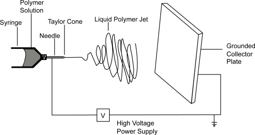
The electrospinning apparatus included a programmable syringe pump (Model NE 500, New Era Pump Systems, Farmingdale, NY) and high voltage power supply (Model No. FC60R2 with positive polarity, Glassman High Voltage, High Bridge, NJ). The pump was operated at a flow rate of 100 μL/min with an electric field of 1 kV/cm. Solutions were loaded into 10 mL syringes with luer-lock connections and used in conjunction with a 4 inch 20 gauge blunt tip needle. The design of the electrospinning set-up was based on a point-plate configuration (Figure 1). Scaffolds for mechanical testing were deposited directly on a collector plate. Scaffolds for cell culture were deposited on polystyrene wafers placed on the plate. Electrospun scaffolds for cell culture were soaked in phosphate buffered saline (PBS) for 12 hrs to remove any residual solvent, sterilized in 70% ethanol for 1 hour, and rinsed again with PBS before seeding with hMSCs.
Figure 1.
Labeled schematic of the electrospinning apparatus used to produce the nanocomposite samples.
Electrospun scaffold characterization
Fiber morphology of the electrospun samples was determined via scanning electron microscopy (SEM) (JEOL JSM-6400 FE) operating at 5 kV. Electrospun samples were coated with Au-Pd at a thickness of 100 Å to reduce charging and produce a conductive surface. Digital images were captured. Transmission electron microscopy (TEM) (JEOL 100S) was performed with samples spun directly on a Cu 400 mesh grid coated with holey thin carbon film. Micrographs were developed and digitally scanned.
Tensile material property tests of electrospun nanocomposites were performed with an Instron Model 5544 using the Blue-hill™ Version 1.00 software on samples of 0–1 wt% MWNT at a crosshead speed of 2.00 mm/min. Scaffold thickness was approximated by averaging 10 measurements for each sample and cross-sectional area (A) was calculated as follows:
where t is the thickness of the sample, w is the width, and v is the volume percentage of fibers.
To determine porosity characteristics, scaffolds were imaged using SEM and imported into NIH Image J™ Software (Bethesda, Maryland) where they were converted to a four pixel system and the void space calculated. Ten images of each MWNT wt% were analyzed.
To determine electrical characteristics of the scaffold material, thin (~1 μm) films were electrospun directly onto flat, interdigitated electrodes on glass (fabricated by standard uv-lithography). Interdigitated electrodes create an electric field parallel to the surface and allow conductance measurements of films grown between and above the digits. The electrodes had twenty-six finger pairs, with each digit 1 mm long, equal digit width and spacing (10 μm), and digit height of approximately 1200 Å (125 Å chromium/1100 Å gold). External wires were connected to the electrode at two contact pads with conductive silver epoxy. Home-made triaxial cables connected the sample, which rested on a copper stage in a vacuum of ~1 × 10⁻⁷ torr, to a Keithley Model 6430 sub-femto amp remote source meter. Standard current-voltage sweeps before and after deposition were conducted (−10 V to 10 V in 0.1 V steps, 15 second delay after voltage changes) and the low-voltage linear region was fit to determine the conductance. All blank electrodes showed similar curves with a measured conductance of ~1 × 10–15 S, which serves as the lower limit of our measurement range.
Human mesenchymal stem cell isolation and expansion
All protocols involving human tissue were approved by the Institutional Review Boards of the University of North Carolina at Chapel Hill and North Carolina State University. Excess adipose tissue from elective plastic surgery procedures was obtained with donor consent. The hMSC isolation method was modified from Gabbay and colleagues (2005). Approximately 50 grams of adipose tissue from a 50 year old Caucasian female was rinsed in phosphate buffered saline (PBS), minced with a scalpel, combined with 50 mL of 0.075% collagenase I (Worthington Biochemical Corp., Lakewood, NJ), 100 I.U. penicillin/100 μg/mL streptomycin (Mediatech, Inc., Herndon, VA) in alpha-modified minimal essential medium (α-MEM with L-glutamine, Invitrogen, Carlsbad CA), and incubated at 37 °C on a rotator for 30 minutes. 50 mL of hMSC growth medium (alpha-modified minimal essential medium (α-MEM with L-glutamine, Invitrogen), 10% fetal bovine serum (Premium Select, Atlanta Biologicals, Lawrenceville, GA), 100 I.U. penicillin /100 μg streptomycin per mL, 200 mM L-glutamine (Mediatech, Inc.) was added, and the suspension was centrifuged for 10 minutes at 10,000 × g. The supernatant was discarded, and the hMSC-rich cell pellet suspended in 160 mM NH4Cl for 10 minutes to lyse red blood cells. Unlysed cells were pelleted by centrifugation for 10 minutes at 10,000 × g, and seeded in tissue culture flasks (one 75 cm2 flask per 5 grams initial tissue) in hMSC growth medium. After 24 hours, cultures were washed with PBS to remove non-adherent cells and supplied with fresh growth medium. Cultures were passaged or cryopreserved at 80% confluency. Re-seeding density was 100,000 cells per 75 cm2 flask. Cells for this study were used at the third passage following isolation.
Cell seeding
Third passage cells were grown to 80% confluency, trypsinized, and resuspended in growth medium. Circular electrospun scaffolds (approximately 1.76 cm diameter) were prewet with PBS and placed in multi-well tissue culture plates. 50,000 cells in a volume of 100 μL were seeded onto each scaffold. The seeded scaffolds were incubated at 37 °C for 30 minutes to allow the cells to adhere, then covered with 2 mL growth medium. Medium was replaced every 3 days. At 1, 3, 7 and 14 days post seeding, scaffolds were removed for viability and proliferation analyses. Viability was determined using a Live/Dead Assay Viability Cytotoxicity kit (calcein AM, ethidium homodimer-1) for Mammalian Cells (Molecular Probes, Eugene, OR) as per manufacturer’s instructions. Live and dead cells were imaged on the scaffolds using fluorescent microscopy. Proliferation was determined by quantifying DNA using the DNA binding dye Hoechst 33258 (Molecular Probes) in a microplate based format. For each time point, scaffolds with attached cells were digested overnight at 60 °C in 2.5 units/mL papain from papaya latex in PBS with 5 mM EDTA and 5 mM cysteine HCl (all reagents from Sigma, St. Louis, MO), then assayed with Hoescht 33258 according to manufacturer’s instructions.
For SEM, scaffolds were fixed with Trump’s fixative and stored at 4 °C. After all time points had been collected, scaffolds were dehydrated in increasing concentrations of ethanol of 50%, 70%, 95%, and 100% for 15 minutes each, then critical point dried (CPD) with CO2. After CPD, samples were sputter-coated with 200 Å Au-Pd then imaged with a JEOL JSM-6360 at 5 kV in secondary electron imaging mode.
Statistical analysis
Experimental results are expressed as mean ± standard deviation. All data were analyzed using ANOVA and Fisher’s LSD for multiple comparisons. Statistical significance was accepted at a p-value < 0.05.
Results
Scaffold characterization
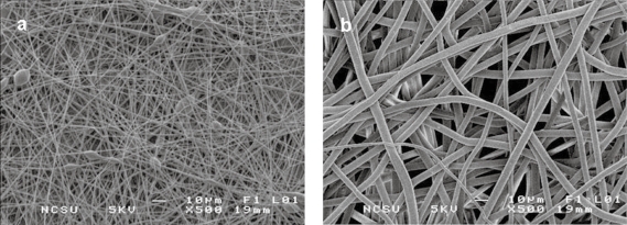
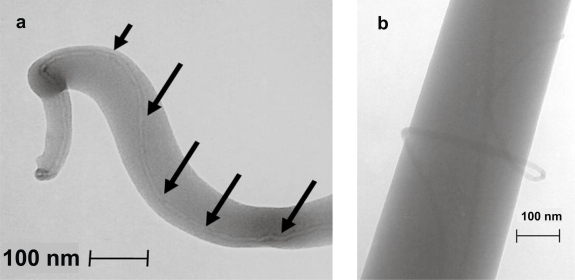
SEM images of electrospun PLA with and without MWNT are shown in Figure 2. Nanocomposite fibers had a markedly smaller average diameter when compared with PLA without MWNT, 700 nm versus approximately 5–8 μm. Both scaffolds featured an interconnected porous network with an average porosity of 87% for all loading levels of MWNT in PLA, and 75% for pure PLA. Taking an average of ten measurements for each image, the void space represented 74.85 ± 2% for pure PLA and 87.6 ± 2% for all MWNT loading levels. TEM was used to visualize the interaction of the MWNT with PLA. Figure 3a shows a fiber with an individual MWNT aligned with the long axis, and encapsulated by the PLA. Occasional fibers with the MWNT incompletely encapsulated were also observed (Figure 3b). The fibers shown are smaller than average to best visualize the MWNT.
Figure 2.
SEM image of electrospun PLA, containing (a) 1 wt% MWNT and (b) 0 wt% MWNT.
Figure 3.
TEM images of electrospun nanocomposite, (a) showing MWNT alignment along fiber axis and (b) showing MWNT entanglement.
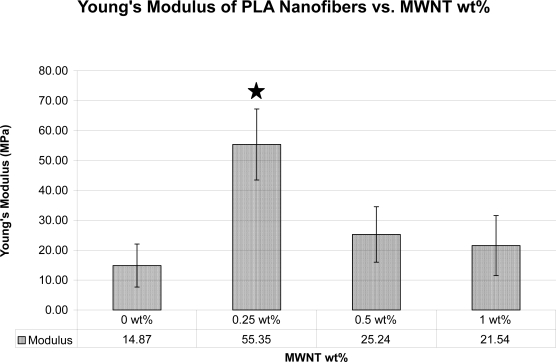
Young’s moduli of scaffolds with different wt% of MWNT was determined (n = 10; Figure 4). Inclusion of MWNT increased the modulus of the electrospun scaffolds, with 0.25 wt% MWNT giving the largest increase, from approximately 15 MPa to 55 MPa.
Figure 4.
Plot of the Young’s modulus of the electrospun fibrous mats by MWNT wt%; (n = 10), Error Bars = Standard Deviation where star indicates significance p-value < 0.05.
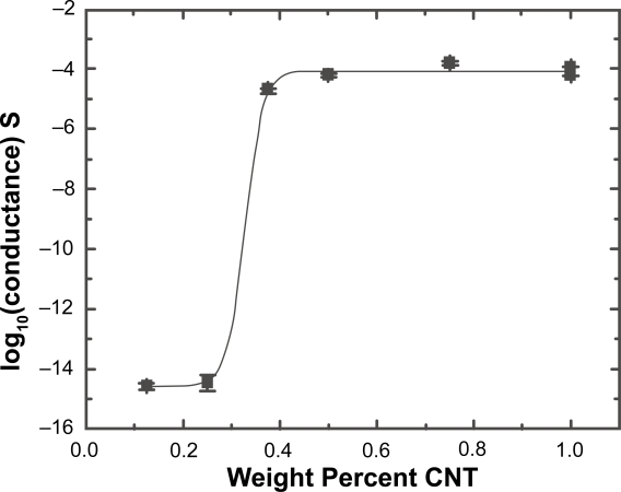
Electrical conductance versus MWNT wt% for an approximately 1 μm thick sample with area of approximately 0.5 mm2 is shown in Figure 5. By fitting the data after Fournier we obtain a percolation threshold of 0.32% (Fournier et al 1997). An estimate of the conductivity above threshold based on the geometry of the system and an assumed value of 87% void space (13% fiber) within the mat yielded a maximum conductivity on the order of 1E-3 S/cm.
Figure 5.
Conductance plot for mats spun from varying MWNT wt% in 20 wt% PLA solution. Two samples are represented at both 0.375 and 1 wt%. The mat conductance, G, is fit after Fournier (1997) with log (G) = log (Gf) + [log (Gm) – log (Gf)]/(1 + exp[b(p – pc)]) where Gm and Gf are the matrix (polymer) and final composite (maximum) conductance, p is the wt%, and pc the critical weight percentage for conductance. The parameter b determines the slope of the curve across the percolation threshold. We find Gm = 2 × 10–15 ± 1 × 10–15 S (indistinguishable from the limit of conductance in our system), Gf = 9 × 10⁻⁵ ± 2 × 10⁻⁵ S, b = 53 ± 19, and pc = 0.32 ± 0.08%.
Cell/scaffold interaction
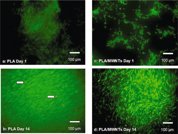
Cell studies were performed on electrospun PLA with 0 and 1 wt% MWNT loadings. Fluorescent dyes were used to visualize live and dead cells on the scaffolds. Calcein AM stained the cytoplasm of live cells green, ethidium homodimer-1 stained the nuclei of dead cells red. The hMSCs were viable on PLA scaffolds both with and without MWNT throughout the culture period (14 days). Three scaffolds were examined at each time point, 1, 3, 7 and 14 days. A maximum of 10 dead cells was observed in any field of view (ten fields viewed per scaffold). Representative images from cultures at days 1 and 14 are shown in Figure 6. Individual viable cells are visible in the images from day 1. Day 14 images show confluent patches of viable cells. Similar patches were visible throughout the scaffolds.
Figure 6.
Live/Dead images of hMSCs on electrospun PLA without MWNT (a, b) and with MWNT (1 wt %) (c, d) where green = live and red = dead cells (indicated by arrows).
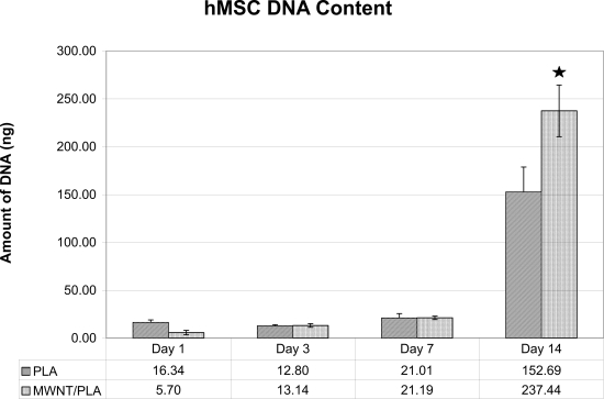
DNA was extracted from three scaffolds at each time point and quantitated (Figure 7), using triplicate samples. hMSCs proliferated during the entire culture period on both types of scaffold. The large increase in DNA from 7–14 days is consistent with exponential growth of the cells. A significant difference was observed between scaffolds with and without MWNT 1 wt% on day 14.
Figure 7.
Number of hMSCs present throughout the course of the experiment on the electrospun tissue scaffolds with and without MWNT. (n = 3, three scaffolds/time point) (Error bars = Standard Deviation), where star indicates significance p-value < 0.05.
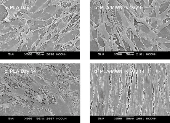
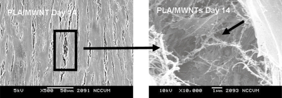
SEM showed that the hMSCs adhered and spread extensively within 1 day of seeding (Figure 8). At 14 days, cells were confluent on both types of scaffold. Cells on scaffolds with MWNT were aligned, whereas cells on PLA alone appeared to have a random orientation.
Figure 8.
SEM image of hMSCs at Day 14, completely confluent on the surface of the electrospun PLA with MWNT.
Discussion
In this study, we demonstrated that adipose-derived hMSCs adhered to and proliferated on nanocomposite scaffolds of electrospun PLA with 1% MWNT and that these scaffolds possessed enhanced conductive properties.
Scaffold characterization
Electrospinning allows for the creation of unique structures with preferred morphologies on the nano-submicron scale. During electrospinning, fiber formation must occur by identifying a critical concentration for the polymer solution that allows for chain entanglements to occur for each molecular chain. This has been reported by Shenoy and colleagues (2005) and we have affirmed this concentration at 20 wt% PLA (Shenoy et al 2005). As shown in Figure 2, we are able to detail the porous nonwoven architecture, which has been reported to be similar to the fibrillar nature of Type I collagen in vivo (Li et al 2006). With the addition of MWNT we observed that there was a tremendous decrease in fiber diameter, possibly due to an increase in the charge density on the Taylor cone during electrospinning (Zeng et al 2003). Scaffolds with MWNT had an average 12% increase in porosity. Porosity is advantageous for cellular ingrowth by allowing for infiltration via cell migration and attachment at multiple focal points. Transmission electron microscopy showed that the MWNT were dispersed within the nanofibers and oriented along the axis of the fiber (Figure 3). This incorporation has been theorized by others to result from the induced electric charge on the fluidic polymer jet (Ko et al 2003). Figure 3a shows that the carbon nanotubes are dispersed and aligned. However, in Figure 3b, the MWNT appear to be entangled; this could be due to the interaction with different segments via van der Waals forces. This entanglement could also be attributed to the length scale of the carbon nanotubes; as the carbon nanotube gets longer, it becomes more difficult to disperse due to a larger increase in the surface area. In general, the entanglement shown in Figure 3b occurred much less frequently, in 2 out of 10 fields of view, than the aligned fiber orientation shown in Figure 3a.
Mechanical properties were determined with tensile testing. The failure strain of all samples was low, commonly between 2%–4% strain. The fibers in the breaking zone showed very little alignment before breaking, demonstrating their highly brittle nature. Previous work has shown that the fracture behavior of electrospun fibrous mats with carbon nanotubes undergoes similar crazing and rupture (Ye et al 2004). The large differences in Young’s Modulus appear to be from the carbon nanotubes not being completely dispersed in the polymer matrix, leading to a reduction in the load transfer efficacy. This behavior has been detected previously in both unaligned and aligned electrospun nanocomposites (Ayutsede et al 2005). In our study, a loading level of 0.25 wt% MWNT had the greatest effect on the mechanical properties of the nanocomposites by increasing Young’s Modulus three-fold. The increase in modulus is a result of stress transfer from the matrix to the filler material. As previous investigators have reported, with MWNT present in a polymeric matrix, as the content of the filler is increased above a critical level, the MWNT aggregate and reduce the effective stress transfer resulting in a decreased modulus (Ko et al 2003; Gorga et al 2004; Dondero et al 2006).
Composites made of an insulating matrix doped with an electrically-conductive filler often display percolation behavior as a function of dopant density (Stauffer et al 1992). Below a certain threshold the filler particles are isolated and thus no current flows. At threshold doping, a single percolating path of dopant (MWNT) is formed and the sample exhibits a dramatically increased conductance. As the filler density further increases, additional paths contribute to the current until the majority of the sample volume is conducting. Above this saturation value, no further increase in conductance as a function of doping is observed. As can be seen in Figure 5, the PLA/MWNT scaffold system exhibited a dramatic percolation behavior accompanied by an increase in conductance of ten orders of magnitude. The critical weight percentage for percolation (0.3%) is much lower than the previous result (13.5%) for MWNT in PLA spin-coated films (Zhang et al 2006). This low threshold value is consistent with the previous report of a critical weight percentage of <0.05% in a single fiber (Sundaray 2006), indicating that such fibrous systems may require only minute doping to obtain significant conductivity, thus minimizing carbon residue in scaffold applications (Sundaray et al 2006).
Human MSC/scaffold interaction
Scaffolds containing 0 wt% and 1 wt% MWNT were electrospun, seeded with hMSCs and incubated for two weeks. Live/Dead staining was performed at 1, 3, 7, and 14 days throughout the experiment. Microscopy showed that hMSCs were able to grow and remain viable on the scaffolds up to 14 days (Figure 6). The localization of cells can be attributed to the three dimensionality of the scaffold, resulting in the appearance of patches of cells in some planes of view. The hMSCs showed an increase in number at day 14. However when viewing the number of cells throughout the course of the experiment, it was noted that there was an approximately equivalent number of hMSCs until day 7. Between days 7 and 14, the hMSC numbers increased dramatically (Figure 8). By quantifying the amount of DNA present in each scaffold, we were able to determine a significant difference at day 14 between the PLA scaffolds with MWNT compared with PLA scaffolds alone (Figure 7). This difference could be attributed to the increased surface area due to the fibers being considerably smaller (Figure 2). SEM images of cells at 14 days showed confluent layers of cells with fibroblastic morphology (Figure 8). By imaging between two cells on this scaffold (Figure 9), we captured the interaction between the hMSCs and the nanofibers. The cells appeared to be completely integrated into the structure of the scaffold, extending cellular processes into and around the nanofibers. This interaction shows that the cells are able to not only become aligned on the scaffold, but that due to the difference in fiber size, hMSCs are able to fully proliferate on electrospun nanocomposite fibers. Further, a pronounced difference in cell morphology is apparent on the two different scaffolds: hMSCs were randomly situated on PLA alone, while they were aligned on PLA with encapsulated MWNT. This occurrence could be attributed to the nanostructured features of the scaffold with MWNT. The PLA/MWNT scaffold’s fibers are considerably smaller in diameter and produce pores on the submicron-scale. As a result, the hMSCs are able to attach at multiple focal points on the surface of the scaffold. However, hMSC migration into the scaffold could be restrained due to the small pore size. In a recent report, cells seeded onto nanofiber and microfiber scaffolds led to similar cell behavior (Pham et al 2006). Our results show that the geometrical features of the scaffold, including fiber diameter and pore size, can influence the orientation and infiltration of hMSCs into the scaffold.
Figure 9.
SEM image at Day 14 of hMSCs integration into electrospun nanocomposite scaffold. Arrows indicate hMSC with processes into scaffold.
Conclusions
In this study, we have produced electrospun nanocomposites by encapsulating MWNT inside PLA nanofibers with fiber diameters on the average of 700 nm. The porous structure was validated by SEM. Integration of the MWNT into the nanofibers was confirmed by TEM. With only minute doping of MWNT, the conductivity of the scaffold increased by approximately ten orders of magnitude. Fluorescence microscopy indicated adipose-derived hMSCs were viable in and on the nanocomposite scaffolds for up to two weeks in culture, and that they proliferated through day 14. The hMSCs formed a confluent three-dimensional construct. With the addition of MWNT in the PLA scaffold, SEM revealed a preferential alignment and orientation of the cells on the scaffold. In conclusion, this work has shown that with the addition of MWNT to electrospun PLA fibers, we are able to reduce the fiber diameter, increase the conductivity of the scaffold, and potentially provide a functional composite for tissue engineering.
Acknowledgments
This work was funded by the Nanotechnology Initiative at North Carolina State, North Carolina Biotechnology Center Institutional Development Grant (EGL), and the Ralph E. Powe Junior Faculty Enhancement Award (EGL). We would like to thank Alan Kinlaw, Kelly Stano for technical assistance, the Center for Chemical Toxicology Research and Pharmacokinetics (CCTRP) and the Laboratory for Advanced Electron and Light Optical Microscopy (LAELOM) at North Carolina State for scaffold image analysis, and the entire Cell Mechanics Laboratory (CML) at North Carolina State.
References
- Andrews PW, Benvenisty N. Starting from building blocks: tissue engineering using stem cells. Current Opinion Biotechnology. 2005;16:485–486. [Google Scholar]
- Ayutsede J, Gandhi M, Sukigara S, et al. Regeneration of Bombyx mori silk by electrospinning. Part 3: characterization of electrospun nonwoven mat. Polymer. 2005;46:1625–1634. [Google Scholar]
- Ayutsede J, Gandhi M, Sukigara S, et al. Carbon nanotube reinforced Bombyx mori silk nanofibers by the electrospinning process. Biomacromolecules. 2006;7:208–214. doi: 10.1021/bm0505888. [DOI] [PubMed] [Google Scholar]
- Battler A, Leor J. Stem Cell and Gene-Based Therapy. London, UK: Springer; 2006. [Google Scholar]
- Chen G-X, Kim H-S, Park BH, et al. Controlled Functionalization of Multiwalled Carbon Nanotubes with various molecular-weight poly(L-lactic acid) Journal of Physical Chemistry B. 2005;109:22237–22243. doi: 10.1021/jp054768n. [DOI] [PubMed] [Google Scholar]
- Dondero WE, Gorga RE. Morphological and mechanical properties of carbon nanotube/polymer composites via melt compounding. Journal of Polymer Science Part B-Polymer Physics. 2006;44:864–878. [Google Scholar]
- Dror Y, Salalha W, Khalfin RL, et al. Carbon nanotubes embedded in oriented polymer nanofibers by electrospinning. Langmuir. 2003;19:7012–7020. doi: 10.1021/la048536b. [DOI] [PubMed] [Google Scholar]
- Elisseeff J, Ferran A, Hwang S, et al. The Role of biomaterials in stem cell differentiation: applications in the musculoskeletal system. Stem Cells and Development. 2006;15:295–303. doi: 10.1089/scd.2006.15.295. [DOI] [PubMed] [Google Scholar]
- Formhals A.1934. Process and apparatus for preparing artificial threads, 1:975,504. USA.
- Fournier J, Boiteux G, Seytre G, et al. Percolation network of polypyrrole in conducting polymer composites. Synthetic Metals. 1997;84:839–840. [Google Scholar]
- Gabbay JS, Mitchell SC, Heller JB, et al. Mechanical stimulation potentiates osteogenic differentiation of human adipose derived stem cells. Journal of The American College Of Surgeons. 2005;201:S49–S49. [Google Scholar]
- Gong HJ, Yang XP, Chen GQ, et al. Study on PLA/MWNT/HA hybrid nanofibers prepared via electrospinning technology. Acta Polymerica Sinica. 2005:297–300. [Google Scholar]
- Gorga RE, Cohen RE. Toughness enhancements in poly(methyl methacrylate) by addition of oriented multiwall carbon nanotubes. Journal of Polymer Science Part B-Polymer Physics. 2004;42:2690–2702. [Google Scholar]
- Habib N, Gordon M, Levicar N, et al. Stem Cell Repair and Regeneration. London, UK: Imperial College Press; 2005. [Google Scholar]
- Hench L, Polak J. Third-generation biomedical materials. Science. 2002;295:1014–1017. doi: 10.1126/science.1067404. [DOI] [PubMed] [Google Scholar]
- Heng BC, Cao T, Stanton LW, et al. Strategies for directing the Differentiation of stem cells into the osteogenic lineage in vitro. Journal of Bone and Mineral Research. 2004;19:1379–1394. doi: 10.1359/JBMR.040714. [DOI] [PubMed] [Google Scholar]
- Hutmacher Scaffolds in tissue engineering bone and cartilage. Biomaterials. 2000;21:2529–2543. doi: 10.1016/s0142-9612(00)00121-6. [DOI] [PubMed] [Google Scholar]
- Iijima S. Helical Microtubules of Graphitic Carbon. Nature. 1991;354:56–58. [Google Scholar]
- Inai R, Kotaki M, Ramakrishna S. Structure and properties of electrospun PLLA single nanofibres. Nanotechnology. 2005;16:208–213. doi: 10.1088/0957-4484/16/2/005. [DOI] [PubMed] [Google Scholar]
- Ko F, Gogotsi Y, Ali A, et al. Electrospinning of continuons carbon nanotube-filled nanofiber yarns. Advanced Materials. 2003;15:1161–1164. [Google Scholar]
- Kotwal A, Schmidt CE. Electrical stimulation alters protein adsorption and nerve cell interactions with electrically conducting biomaterials. Biomaterials. 2001;22:1055–1064. doi: 10.1016/s0142-9612(00)00344-6. [DOI] [PubMed] [Google Scholar]
- Laurencin C. Bone Graft Substitutes. Bridgeport: ASTM International; 2003. [Google Scholar]
- Lee JH, Park TG, Park HS, et al. Thermal and mechanical characteristics of poly(L-lactic acid) nanocomposite scaffold. Biomaterials. 2003;24:2773–2778. doi: 10.1016/s0142-9612(03)00080-2. [DOI] [PubMed] [Google Scholar]
- Li C, Vepari C, Jin H-J, et al. Electrospun silk-BMP-2 scaffolds for bone tissue engineering. Biomaterials. 2006;27:3115–3124. doi: 10.1016/j.biomaterials.2006.01.022. [DOI] [PubMed] [Google Scholar]
- Lieberman J, Friedlaender G. Bone Regeneration and Repair: Biology and Clinical Applications. Totowa: Humana Press; 2005. [Google Scholar]
- Ma P. Scaffolds for tissue fabrication. Materials Today. 2004;7:30–40. [Google Scholar]
- Macdonald RA, Laurenzi BF, Viswanathan G, et al. Collagen-carbon nanotube composite materials as scaffolds in tissue engineering. Journal of Biomedical Materials Research Part A. 2005;74A:489–496. doi: 10.1002/jbm.a.30386. [DOI] [PubMed] [Google Scholar]
- Monteiro-Riviere N, Inman A, Wang Y, et al. Surfactant effects on carbon nanotube interactions with human keratinocytes. Nanomedicine: Nanotechnology Biology and Medicine. 2005;1:293–299. doi: 10.1016/j.nano.2005.10.007. [DOI] [PubMed] [Google Scholar]
- Moore VC, Strano MS, Haroz EH, et al. Individually suspended single-walled carbon nanotubes in various surfactants. Nano Letters. 2003;3:1379–1382. [Google Scholar]
- Pedrotty DM, Koh J. Engineering skeletal myoblasts: roles of three-dimensional culture and electrical stimulation. Am. J Physiol Heart Circ Physiol. 2005;288:1620–1626. doi: 10.1152/ajpheart.00610.2003. [DOI] [PubMed] [Google Scholar]
- Pham QP, Sharma U, Mikos AG. Electrospinning of polymeric nanofibers for tissue engineering applications: A review. Tissue Engineering. 2006;12:1197–1211. doi: 10.1089/ten.2006.12.1197. [DOI] [PubMed] [Google Scholar]
- Pham QP, Sharma U, Mikos AG. Electrospun poly(caprolactone) microfiber and multilayer nanofiber/microfiber scaffolds: characterization of scaffolds and measurement of cellular infiltration. Biomacromolecules. 2006;7:2796–2805. doi: 10.1021/bm060680j. [DOI] [PubMed] [Google Scholar]
- Pittenger MF, Mackay AM, Beck SC, et al. Multilineage potential of adult human mesenchymal stem cells. Science. 1999;284:143–147. doi: 10.1126/science.284.5411.143. [DOI] [PubMed] [Google Scholar]
- Poncharal P, Wang ZL, Ugarte D, et al. Electrostatic deflections and electromechanical resonances of carbon nanotubes. Science. 1999;283:1513–1517. doi: 10.1126/science.283.5407.1513. [DOI] [PubMed] [Google Scholar]
- Ren ZF, Huang ZP, Xu JW, et al. Synthesis of large arrays of well-aligned carbon nanotubes on glass. Science. 1998;282:1105–1107. doi: 10.1126/science.282.5391.1105. [DOI] [PubMed] [Google Scholar]
- Sharma B, Elisseeff J. Engineering structurally organized cartilage and bone tissues. Annals of Biomedical Engineering. 2004;32:148–159. doi: 10.1023/b:abme.0000007799.60142.78. [DOI] [PubMed] [Google Scholar]
- Shenoy SL, Bates WD, Frisch HL, et al. Role of chain entanglements on fiber formation during electrospinning of polymer solutions: good solvent, non-specific polymer-polymer interaction limit. Polymer. 2005;46:3372–3384. [Google Scholar]
- Smart SK, Cassady AI, Lu GQ, et al. The biocompatibility of carbon nanotubes. Carbon. 2006;44:1034–1047. [Google Scholar]
- Stauffer D, Aharony A. Introduction to Percolation Theory. Washington DC: Taylor & Francis; 1992. [Google Scholar]
- Sundaray B, Subramanian V, Natarajan TS, et al. Electrical conductivity of a single electrospun fiber of poly(methyl methacrylate) and multiwalled carbon nanotube nanocomposite. Applied Physics Letters. 2006:88. [Google Scholar]
- Supronowicz PR, Ajayan PM, Ullmann KR, et al. Novel current-conducting composite substrates for exposing osteoblasts to alternating current stimulation. Journal of Biomedical Materials Research. 2002;59:499–506. doi: 10.1002/jbm.10015. [DOI] [PubMed] [Google Scholar]
- Tan S-H, Inai R, Kotak IM, et al. Systematic parameter study for ultra-fine fiber fabrication via electrospinning process. Polymer. 2005:6128–6134. [Google Scholar]
- Ye HH, Lam H, Titchenal N, et al. Reinforcement and rupture behavior of carbon nanotubes-polymer nanofibers. Applied Physics Letters. 2004;85:1775–1777. [Google Scholar]
- Zeng J, Xu X, Chen X, et al. Biodegradable electrospun fibers for drug delivery. Journal of Controlled Release. 2003;92:227–231. doi: 10.1016/s0168-3659(03)00372-9. [DOI] [PubMed] [Google Scholar]
- Zhang D, Kandadai MA, Cech J, et al. Poly(L-lactide)(PLLA)/ multiwalled carbon nanotube (MWCNT) composite: characterization and biocompatibility evaluation. Journal of Physical Chemistry B. 2006;110:12910–12915. doi: 10.1021/jp061628k. [DOI] [PubMed] [Google Scholar]
- Zhao B, Hu H, Mandal SK, et al. A bone mimic based on the self-assembly of hydroxyapatite on chemically functionalized single-walled carbon nanotubes. Chemistry Of Materials. 2005;17:3235–3241. [Google Scholar]
- Zong XH, Bien H, Chung CY, et al. Electrospun fine-textured scaffolds for heart tissue constructs. Biomaterials. 2005;26:5330–5338. doi: 10.1016/j.biomaterials.2005.01.052. [DOI] [PubMed] [Google Scholar]
- Zong XH, Kim K, Fang DF, et al. Structure and process relationship of electrospun bioabsorbable nanofiber membranes. Polymer. 2002;43:4403–4412. [Google Scholar]


