Abstract
Electrochemical biosensors pose an attractive solution for point-of-care diagnostics because they require minimal instrumentation and they are scalable and readily integrated with microelectronics. The integration of electrochemical biosensors with microscale devices has, however, proven to be challenging due to significant incompatibilities among biomolecular stability, operation conditions of electrochemical sensors, and microfabrication techniques. Toward a solution to this problem, we have demonstrated here an electrochemical array architecture that supports the following processes in situ, within a self-enclosed microfluidic device: (a) electrode cleaning and preparation, (b) electrochemical addressing, patterning, and immobilization of sensing biomolecules at selected sensor pixels, (c) sequence-specific electrochemical detection from multiple pixels, and (d) regeneration of the sensing pixels. The architecture we have developed is general, and it should be applicable to a wide range of biosensing schemes that utilize gold–thiol self-assembled monolayer chemistry. As a proof-of-principle, we demonstrate the detection and differentiation of polymerase chain reaction (PCR) amplicons diagnostic of human (H1N1) and avian (H5N1) influenza.
Introduction
As more diagnostic tests are being performed at patients' bedsides and in physicians' offices, outpatient clinics, emergency rooms, and intensive care units, the demand for rapid, point-of-care diagnostics (POC) continues to rise.1 Among many approaches toward this end, electrochemical biosensors pose an attractive solution because they require minimal instrumentation and because they are readily integrated with microelectronics.2 Previously, we and others have demonstrated a broad class of reagentless, electrochemical biosensors composed of either single-stranded probe DNA (E-DNA) or aptamer DNAs (E-AB) that have been modified with a redox reporter group and covalently attached to an interrogating electrode (Figure 1). Binding of the relevant target to these modified probes alters the efficiency with which electrons are transferred to the electrode and produce a readily measurable change in the sensing current that is monotonically related to analyte concentration over a wide dynamic range.3 The E-DNA and E-AB platforms are versatile, with low detection limit (down to 400 fM) and high specificity (single-base discrimination), and sensors have been reported for the detection of DNA and RNA,4–6 proteins,7–10 and small molecules.11,12 Moreover, E-DNA and E-AB sensors are selective enough to deploy directly in blood serum, food, soil samples, and other contaminated materials.13 When coupled with its stability, broad and linear dynamic range, and reagentless, reusable operation, this electrochemical biosensor platform appears well-suited for miniaturized arrays and integration into microfabricated devices.
Figure 1.
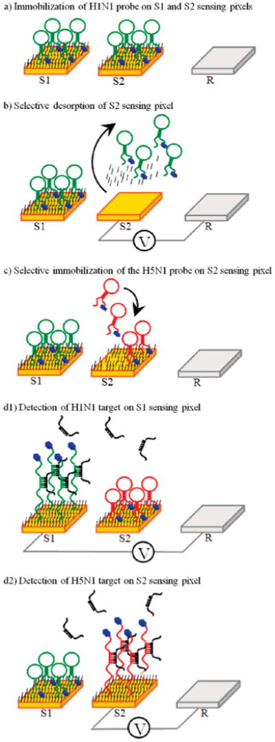
Process flow for the fabrication and operation of a multianalyte microfluidic electrochemical array and mechanism of the E-DNA sensor. (a) First, one of the two probe DNAs (H5N1) is immobilized with a C6 thiol passivating agent on both sensing pixels (S1 and S2). (b) Next, a positive potential is selectively applied to the second sensing element (S2), leading to oxidative desorption of the passivating alkanethiol and the probe DNA. (c) The second probe (H1N1) and the C6 coadsorbate are selectively adsorbed to the second electrode (S2), and the device is ready for target detection. (d1) Analyte containing only the H1N1 target hybridizes with the probe DNA on S1, yielding a decreased reduction current in the AC voltammetry scan from that sensor. (d2) Analyte containing only H5N1 target decreases the faradaic current only from sensor S2.
Despite this promising potential, the integration of electrochemical biosensors with monolithic, microscale devices has proven to be challenging, primarily because of incompatibilities among the rather limited stability of biomolecules, the harsh conditions employed in electrochemistry, and the materials and processes required for microfabrication. For example, the highly corrosive agents generally employed in the cleaning step of electrochemical biosensors (e.g., mixtures of sulfuric acid and hydrogen peroxide) are incompatible with many of the materials employed in microfluidic devices. Likewise, the fabrication methods typically used for device integration are often incompatible with the biosensor molecule, precluding sensor synthesis prior to integration with microfluidics. Finally, it has proven difficult to selectively modify individual sensing elements in a closely packed array within a monolithic device, where line-of-sight physical access is not feasible.14
In this work, we describe a scalable device architecture for integrating electrochemical biosensors within microfluidic devices and demonstrate (a) in situ cleaning and preparation of the electrodes, (b) in situ electrochemical addressing, patterning, and immobilization of probes at selected sensor pixels, (c) sequence-specific electrochemical detection from multiple pixels, and (d) in situ regeneration of sensing pixels. The methods developed in this work are applicable to both the hybridization-based nucleic acid detection (E-DNA) as well as aptamer-based protein and small molecule detection (E-AB) because the method of sensor preparation and readout are identical. As a proof-of-principle, here we employ the E-DNA architecture to perform simultaneous monitoring and differentiation of DNA sequences representative of PCR amplicons derived from human (H1N1) and avian (H5N1) influenza as the first step in the development of an integrated amplification-and-detection device.
Materials and Methods
DNA Probes and Buffers
DNA targets representative of PCR amplicons for H1N1 {5′-ATGTAGGACCATGAGTTTGCAGTGAGTAGAAGGTCACATTCTGGATTGCC-3′} and H5N1 {5′-GAGGTCATTGACTGGATTGGCCTTCTCCACTATGTAAGACCATTCCGGCA-3′} were synthesized by Sigma-Genosys (Woodlands, TX) and were deployed at a target concentration of 400 nM in all experiments, which is representative of the final concentration achievable via PCR.15 E-DNA probe sequences containing a methylene blue (MB) electrochemical reporter at their 3′ termini and a six-carbon alkane thiol on their 5′ termini were purchased from Biosearch, Inc. (Novato, CA). Two probe sequences against H1N1 (5′-HS-(CH2)6-GCAGTTCACTGCAAACTCATGGACTGCT-(CH2)7-MB-3′) and H5N1 (5′-HS-(CH2)6-GCAGTAGAAGGCCAATCCAGTCACTGC-(CH2)7-MB-3′), were employed. 6-Mercapto-1-hexanol (Sigma-Aldrich, St. Louis, MO) and tris(2-carboxyethyl) phosphine hydrochloride (TCEP) (Molecular Probes, Carlsbad, CA) were used as purchased. Saline sodium citrate buffer (6× SSC; 0.9 M NaCl, 90 mM sodium citrate, pH 7) was used during in situ probe preparation and detection.
Microfabrication
The devices were processed using a modular fabrication architecture.
Electrode Substrates
The platinum interconnects (20 nm titanium/180 nm platinum) were patterned on a 4 in. borofloat glass wafer (University Wafers, Boston, MA) through the standard lift-off process. A 20 nm titanium layer was then evaporated onto the platinum lines and passivated with 450 nm of SiO2. Finally, 20 nm of titanium and 180 nm of gold layers were evaporated to form the working electrodes.
Chamber Substrates
The borofloat glass wafers were cleaned using the standard piranha (H2SO4/H2O2, 1:2 v/v) cleaning process, and the sacrificial amorphous silicon layer (200 nm) was deposited on the wafers using a Unaxis ICP (Pfäffikon, Switzerland) high-density plasma-enhanced chemical vapor deposition (PECVD) method. The amorphous silicon was patterned using standard photolithography and etched in the shape of the chamber using a Technics PEII plasma etching system (Osaka, Japan). The chamber was then isotropically etched into the chamber substrate using 49% HF to a depth of 35 μm.
Bonding and Fluidic Interface
The processed substrates were diced and cleaned using acetone, isopropanol, and deionized (DI) water and then dried in a nitrogen flow and dehydrated at 120 °C. The chamber substrate was then aligned to the electrode substrate and placed in a high vacuum oven and fusion bonded at 630 °C for 3 h. After fusion bonding, the device was cleaned using acetone and isopropanol. Next, pneumatic valves fabricated with polydimethylsiloxane (PDMS) were assembled in steps similar to those described in Grover et. al.16 Finally, Tygon eyelets were epoxy-glued to the fluidic inlet and outlet of the completed chip. Approximately 10 devices were fabricated and characterized in the experiment.
Sensor Fabrication
The gold sensor electrodes were electrochemically cleaned within the microfluidic device in situ before modification with thiolated DNA probes. Cleaning was achieved by performing cyclic voltammetry (CV) in 0.1 M H2SO4 where the potential was swept between 0 and 1.8 V for 5 min at a rate of 0.5 V/s for each sensing electrode. The cleaning process corresponds to a succession of oxidation of the gold pixel surface followed by reductive stripping of the oxide. The gold oxidation and reduction peaks are observed on the CV scans. Immediately after the end of the cleaning cycle, the chamber was rinsed with DI water and the probe DNA was immobilized onto the gold surface by incubating the clean electrodes with 2 μM DNA for 1 h, which produces probe densities of ∼2 × 10¹² molecules/cm2 on the sensing electrode.3 The electrodes were then passivated by incubation in 2 mM mercapto-1-hexanol (C6) for 2 h. After rinsing the chamber with 6× SSC buffer, AC voltammetric scans were acquired for all three working electrodes using a commercial potentiostat (CH Instruments, Austin, TX). The chamber was then filled with a solution of H1N1 target DNA in 6× SSC buffer, and voltammetric scans were acquired after 25 min. Voltammetric scans were also acquired after regeneration of the sensing electrodes with room-temperature deionized water.
Differential Labeling
After being cleaned, the H5N1 probe was immobilized on both the S1 and S2 electrodes, and passivated with a C6 layer. AC voltammetry scans in 6× SSC buffer were performed to verify that the process had successfully completed. Next, S2 was connected to the electrochemical workstation in a three-electrode setup, and a positive potential sweep (from 0.725 to 0.75 V at a scan rate of 0.0001 V/s) was applied until total desorption of the initial H5N1/C6 layer was observed in the AC voltammetry scans. The H1N1 probe was then injected, followed by passivation with C6. Finally, both pixels were interrogated in the manner described above.
Results
Device Architecture and Fabrication
The microfluidic electrochemical array is a glass device fabricated using a modular architecture; first, the electrode and chamber substrates are processed individually using standard photolithography, thin-film deposition, and etching steps (Figure 2a and b). The two substrates are then fusion bonded (Figure 2c) to complete the processing of the monolithic device (Figure 2d). This modular architecture is necessary because the device must withstand relatively caustic conditions (i.e., sulfuric acid) used for the in situ cleaning of the electrode sensing pixels which is critical for the proper attachment of the probe DNA and the alkanethiol passivation layer to the sensing electrodes.4,17 Thus, many polymeric materials including polyimide, a material commonly used in microfluidic devices, cannot be employed because it produces unacceptable contamination on the electrodes (data not shown). The volume of the detection chamber is 750 nL, and the fluidic control of the analyte in and out of this chamber is achieved through the use of pneumatically driven PDMS valves16 (Figure 2c). These valves provide clean and efficient sealing of the chamber during electrochemical measurements and do not appear to adversely affect sensor fabrication or target detection.
Figure 2.
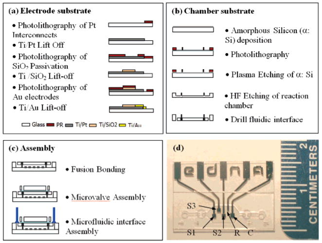
Device architecture of the microfluidic electrochemical array and microfabrication process flow. The modular architecture allows independent processing of (a) the electrode substrate and (b) the chamber substrate, which are then fusion bonded to form a monolithic device. (c) Integrated PDMS microvalves enable precise fluidic metering of analyte solutions into the 750 nL detection chamber. (d) Optical micrograph of the device illustrating the gold sensor electrodes (S1, S2, and S3), platinum reference electrode (R), and counter electrode (C). The sensor electrodes are 900 μm × 900 μm in size, and the center-to-center pitch between S1 and S2 is 2 mm.
The modular fabrication architecture is also advantageous because it allows the fabrication of complex monolithic structures using standard planar fabrication techniques. For example, to obtain a reproducible, electrochemical signal with low background levels from the working electrodes, it is imperative that only the gold surfaces of defined size are exposed to the analyte solution. If other conductors (i.e., the underlying platinum interconnects) are exposed to the electrolyte solution, the additional current drawn through these exposures will decrease the observed signal-to-noise ratio. For this reason, a homogeneous and defect-free insulating layer must be employed. In the device, the underlying platinum interconnects were passivated using a silicon dioxide layer, leaving only the gold electrodes exposed within the electrochemical chamber (Figure 2a). We find that a 450 nm SiO2 passivation layer deposited by the high-density plasma enhanced chemical vapor deposition (PECVD) method effectively eliminates these non-faradaic currents and, critically, it is stable under the conditions employed to both fabricate and operate the E-DNA sensors. As an initial test of our fabrication approach, we have simultaneously labeled all three sensors (S1, S2, and S3; Figure 2d) with the H1N1 probe and challenged them with a solution of the target oligonucleotides. Given our target concentration (400 nM) and chamber volume (750 nL), a typical sample contains 1.8 × 10¹¹ molecules (300 fmol) of the analyte. The device achieves excellent pixel-to-pixel reproducibility (Figure 3, dashed lines), and the observed change in peak current across the three is 59% ± 4% (mean and standard deviation). After use, the sensor is fully regenerated after a simple wash with 1 mL of room-temperature DI water: the current from each of the three pixels returns to ∼98% of its initial value, and, across the three pixels, we observe only a 2% standard deviation (Figure 3, dotted lines). This observation provides additional support that the signal is arising from the specific interactions with the target molecule rather than, for example, degradation of the probe. Of note, due to the fact that the integration of the traditional silver–silver chloride reference electrode is incompatible with our current device fabrication scheme, we have utilized the platinum electrode as a pseudo-reference electrode. Because of this, the observed reduction potential of the methylene blue redox tag varies slightly from experiment to experiment and the potentials in the figures have been normalized by peak picking. Despite the slight potential differences, the sensors' behaviors are identical to those measured with a silver–silver chloride reference electrode in a standard, macroscale, three-electrode electrochemical cell.
Figure 3.
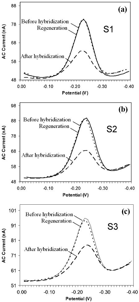
Pixel-to-pixel reproducibility for DNA detection. All three sensing electrodes (S1, S2, and S3) within the array were modified with the H1N1 probe DNA. The MB reduction current from each working electrode is indicated before (solid line) and after (dashed line) hybridization with the H1N1 target. The sensors yielded a uniform signal of 59 ± 4%. The measurements were taken 25 min after injection of the target at 400 nM. All three probes were then regenerated with room-temperature DI water (dotted line) with excellent recovery and reproducibility (98 ± 2%).
Electrochemical Patterning of Sensors and Detection of Multiple Targets
As noted above, plastic microfluidic substrates, such as polyimide, are poorly compatible with electrochemical sensors due to electrode fouling by materials leached from the plastic and poor resistance of the plastic to the harsh, highly oxidizing conditions required to remove this contamination post facto (data not shown). For this reason, we have employed glass substrates. Immobilized probe DNA, however, cannot withstand the high temperatures (630 °C) involved in glass–glass bonding. It is thus necessary to selectively modify the sensor electrodes by electrochemically addressing them after device fabrication is complete. Many of the traditional methods of selectively patterning the biosensors, however, are not compatible with electrodes within enclosed microfluidic chambers. For example, microcontact printing and microstamping18,19 are effective for flat, open surfaces, but they are extremely challenging to employ in self-enclosed microfluidic devices because direct physical access to the pixels is not available. To circumvent this limitation, we and others have successfully patterned multiple electrodes electrochemically through the selective adsorption20,21 and desorption of thiols15,21,22 such that different probe DNA sequences are presented on separate electrodes. Importantly, for densely packed sensor pixels, it is imperative that the conditions employed during the differential labeling process are sufficiently mild, so that the selective adsorption/desorption processes does not degrade the neighboring, previously modified electrodes. Moreover, reductive desorption leads to the production of free thiols, which can subsequently reattach to the surface of the electrode.23,24 Instead, we have thus developed an oxidative method that appears irreversible.25,26
Our method of electrochemical oxidative desorption is selective, mild and does not affect neighboring electrodes which are 2 mm apart (Figure 4), and prior studies suggest that <100 μm spacing can be supported:15 First, the H5N1 probe with a C6 passivation layer is immobilized on both S1 and S2 sensing pixels. At this step, methylene blue reduction AC voltammetry scans from the electrodes produce a robust signal, indicating the effective immobilization of the H5N1/C6 layers (Figure 4a, inset). Next, the H5N1/C6 layer is selectively desorbed from the S2 sensing pixel by applying a positive potential sweep from 0.725 to 0.75 V at a scan rate of 0.0001 V/s, a potential range that is effective in removing the thiolated DNA as well as the C6 coadsorbate. The potential range, however, is kept small, thus eliminating the possibility of generating undesirable reactive species (e.g., chlorine gas), which may degrade the sensing electrodes.27–29 Because of this, we observe no significant degradation of adjacent pixels in the geometry employed here (Figure 2d). The potential sweep is repeated until total desorption of the H5N1/C6 layers is measured through the decrease of the methylene blue AC voltammetry reduction signal with an increase of the faradaic current during the positive potential sweep, which indicates the exposure of the gold layer in the S2 sensing pixel (Figure 4a). Finally, a last short voltage sweep at a higher scan rate (e.g., 0.001 V/s) is performed, as it has been shown to help clean the gold layer (data not shown). The methylene blue reduction scans of the S1 sensing pixel show that selective oxidation only has a minimal effect on the H5N1/C6 layer (Figure 4b, dashed line). Finally, the H1N1 probe with the C6 passivation layer is then adsorbed to the S2 sensing pixel in the manner described above to complete the immobilization process.
Figure 4.
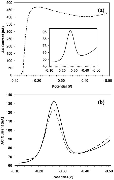
Selective electrochemical immobilization of probe DNA onto closely packed sensing electrodes within the enclosed device. The oxidative desorption of probe DNA is selective and gentle on neighboring electrodes. (a) First, the H5N1 probe and the C6 thiol coadsorbate are immobilized on sensing pixels S1 and S2. The AC voltammetry scan of S2 indicates the effective immobilization of the probe (inset). Next, the H5N1/C6 layer is selectively desorbed from the S2 sensing pixel by applying a positive potential sweep from 0.725 to 0.75 V at 0.0001 V/s. The complete desorption of the layer is indicated by the very large increase in the current from the exposure of the gold layer (dashed line). (b) The AC voltammetry scan taken from the probe-modified sensing pixel S1 before (solid line) and after (dashed line) stripping of the S2 sensing pixel indicates only mild degradation of this closely packed neighbor.
After the S1 and S2 sensing pixels were immobilized with H5N1 and H1N1 probes, respectively (Figure 5 a and b, solid lines), we tested the device against DNA sequences diagnostic of human or avian influenza. The responses of the E-DNA are rapid and specific. First, the H5N1 target was introduced into the device, and reduction scans of S1 and S2 were acquired within 20 min. Under these conditions, the device robustly and specifically detects its target DNA; a 38% change in the signal is observed for S1 (Figure 5a, dashed lines), whereas only 3% change is measured for S2 (Figure 5b, dashed lines). Following this challenge, the sensing electrodes were regenerated by flowing distilled, deionized water through the chamber followed by 6× SSC buffer. As indicated by the reduction scans, the sensor electrodes are almost completely (97%) regenerated via this approach (Figure 5c and d, solid lines). After regeneration, the H1N1 target was introduced and reduction scans were acquired within 20 min, which is more than sufficient for complete sensor equilibration under these conditions.3 In this case, while the S1 signal decreased 3%, indicating no significant hybridization of the target with the H1N1 probe (Figure 5c, dashed lines), a 46% change in signal was measured for S2 (Figure 5d, dashed lines).
Figure 5.
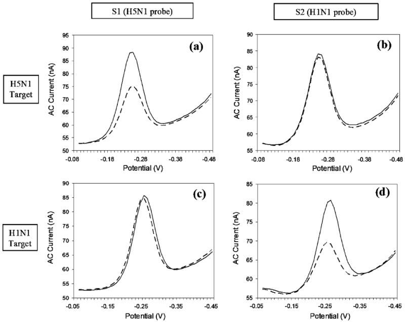
Sequence-specific detection of H5N1 and H1N1 targets. (a) When challenged with the target H5N1 (concentration = 400 nM), sensor S1 (immobilized with H5N1 probe) responds as expected with a 38% change in signal. (b) The H5N1 target does not, however, significantly affect the signal from sensor S2 (immobilized with the H1N1 probe). After regeneration of the sensors with DI water, the device is challenged with the H1N1 target (concentration = 400 nM). (c) S1 demonstrates minimal response to the target (3%), whereas d) S2 responds with a 46% change in signaling current.
Discussion
We have presented a microfluidic electrochemical device that supports in situ electrode cleaning preparation, selective DNA probe immobilization, microfluidic metering, sequence-specific target detection, and efficient regeneration of sensing pixels, all in a self-enclosed, monolithic glass chip. The completed device consists of a small array of sub-millimeter working electrodes and their complementary reference and counter electrodes contained within a sub-microliter sample chamber. After in situ patterning of the sensing pixels, the device was successfully employed to detect and distinguish between DNA sequences indicative of the human and avian influenza virus.
Previously, there has been a multitude of different detection modes for on-chip amperometry, conductometry, and potentiometry.30,31 In our case, the fabrication of an integrated electrochemical array required several advances. First, a modular microfabrication architecture was developed, in which the electrode and fluidic substrates are processed separately and fusion bonded at a later step. This approach enabled the fabrication of a multilayer electrode structure which provides AC voltammetry signals with high signal-to-noise ratios. Critically, the use of glass rather than polymer materials allows for efficient electrode cleaning prior to deposition of biomolecular probes, and thus supports high quality, low-background electrochemical sensing. The second advance was the use of a selective electrochemical method to differentially label individual sensing pixels in situ, inside of an enclosed device, rather than the use of physical spotting methods (e.g., pin tools, microcontact printing, and microstamping). The electrochemical addressing and selective patterning of the DNA probes allowed a single sensor pixel within an array to be functionalized without contaminating the neighboring electrodes, and the method is, presumably, applicable to any probe that can be immobilized via gold–thiol self-assembled monolayer formation. The advantage of this approach is significant because it does not require any mechanical alignments and does not need line-of-sight physical access, and thus, this approach may be extended to a variety of miniaturized structures without geometric constraints. One drawback of this approach is that each pixel must be addressed in series. However, it would be relatively straightforward to automate the functionalization of many devices in batches, in a parallel manner, which would significantly increase the throughput.
In conclusion, by combining the technologies for reagentless electrochemical biosensors, electrochemical patterning, and microfluidic integration, we have fabricated a two-pixel electronic device capable of differentiating the DNA sequences from human (H1N1) and avian (H5N1) influenza in a reagentless manner. The extension of this architecture to more than two pixels, and to detect multiple targets simultaneously, is a subject of current investigation. Here, although nucleic acid detection was shown as a proof-of-principle, the devices and methods can be easily extended for the detection of proteins and small molecules through the use of DNA aptamer-based sensors7 for which the methods of sensor preparation and readout are identical. Likewise, while the E-DNA architecture employed here is a “signal-off” sensor, in which the presence of the target suppresses the signaling current, several “signal-on” architectures have recently been reported,32,33 and it should be equally facile to integrate them into the device. Such integration of a wide class of biosensors with integrated microfluidic electrochemical devices may enable a viable route toward realizing the potential of point-of-care detection technology.
Acknowledgments
We are thankful for financial support from the ARO Institute for Collaborative Biotechnologies (DAAD1903D004), DARPA/DMEA-CNID Grants H94003-05-2-0503 and DMEA90-02-2-0215. We thank Dr. Jim Sumner, Dr. Yi Xiao, and Patrick Freudenthal for helpful discussions. Microfabrication was carried out in the Nanofabrication Facility at UC Santa Barbara.
References
- 1.Huckle D. Expert Rev Med Devices. 2006;3:421–426. doi: 10.1586/17434440.3.4.421. [DOI] [PubMed] [Google Scholar]
- 2.Wang J. Biosens Bioelectron. 2006;21:1887–1892. doi: 10.1016/j.bios.2005.10.027. [DOI] [PubMed] [Google Scholar]
- 3.Ricci F, Lai RY, Heeger AJ, Plaxco KW, Sumner JJ. Langmuir. 2007;23:6827–6834. doi: 10.1021/la700328r. [DOI] [PMC free article] [PubMed] [Google Scholar]
- 4.Fan C, Plaxco KW, Heeger AJ. Proc Natl Acad Sci USA. 2003;100:9134–9137. doi: 10.1073/pnas.1633515100. [DOI] [PMC free article] [PubMed] [Google Scholar]
- 5.Immoos CE, Lee SJ, Grinstaff MW. J Am Chem Soc. 2004;126:10814–10815. doi: 10.1021/ja046634d. [DOI] [PubMed] [Google Scholar]
- 6.Mao Y, Luo C, Ouyang Q. Nucleic Acids Res. 2003;31:e108. doi: 10.1093/nar/gng108. [DOI] [PMC free article] [PubMed] [Google Scholar]
- 7.Xiao Y, Lubin AA, Heeger AJ, Plaxco KW. Angew Chem Int Ed. 2005;44:5456–5459. doi: 10.1002/anie.200500989. [DOI] [PubMed] [Google Scholar]
- 8.Xiao Y, Piorek BD, Plaxco KW, Heeger AJ. J Am Chem Soc. 2005;127:17990–17991. doi: 10.1021/ja056555h. [DOI] [PubMed] [Google Scholar]
- 9.Radi AE, Acero Sanchez JL, Baldrich E, O'Sullivan CK. J Am Chem Soc. 2006;128:117–124. doi: 10.1021/ja053121d. [DOI] [PubMed] [Google Scholar]
- 10.Lai RY, Plaxco KW, Heeger AJ. Anal Chem. 2007;79:229–233. doi: 10.1021/ac061592s. [DOI] [PubMed] [Google Scholar]
- 11.Baker BR, Lai RY, Wood MS, Doctor EH, Heeger AJ, Plaxco KW. J Am Chem Soc. 2006;128:3138–3139. doi: 10.1021/ja056957p. [DOI] [PubMed] [Google Scholar]
- 12.Zuo X, Song S, Zhang J, Pan D, Wang L, Fan C. J Am Chem Soc. 2007;129:1042–1043. doi: 10.1021/ja067024b. [DOI] [PubMed] [Google Scholar]
- 13.Lubin AA, Lai RY, Baker BR, Heeger AJ, Plaxco KW. Anal Chem. 2006;78:5671–5677. doi: 10.1021/ac0601819. [DOI] [PubMed] [Google Scholar]
- 14.Zhang Y, Salaita K, Lim JH, Lee KB, Mirkin CA. Langmuir. 2004;20:962–968. doi: 10.1021/la030392y. [DOI] [PubMed] [Google Scholar]
- 15.Lai RY, Lee SH, Soh HT, Plaxco KW, Heeger AJ. Langmuir. 2006;22:1932–1936. doi: 10.1021/la052132h. [DOI] [PubMed] [Google Scholar]
- 16.Grover WH, Skelley AM, Liu CN, Lagally ET, Mathies RA. Sens Actuators B. 2003;89:315–323. [Google Scholar]
- 17.Lai RY, Lagally ET, Lee SH, Soh HT, Plaxco KW, Heeger AJ. Proc Natl Acad Sci USA. 2006;103:4017–4021. doi: 10.1073/pnas.0511325103. [DOI] [PMC free article] [PubMed] [Google Scholar]
- 18.Kumar A, Biebuyck HA, Whitesides GM. Langmuir. 1994;10:1498–1511. [Google Scholar]
- 19.Jackman RJ, Wilbur JL, Whitesides GM. Science. 1995;269:664–666. doi: 10.1126/science.7624795. [DOI] [PubMed] [Google Scholar]
- 20.Badia A, Arnold S, Scheumann V, Zizlsperger M, Mack J, Jung G, Knoll W. Sens Actuators B. 1999;54:145–165. [Google Scholar]
- 21.Tender LM, Worley RL, Fan HY, Lopez GP. Langmuir. 1996;12:5515–5518. [Google Scholar]
- 22.Niu L, Knoll W. Anal Chem. 2007;79:2695–2702. doi: 10.1021/ac061678l. [DOI] [PubMed] [Google Scholar]
- 23.Gorman CB, Biebuyck HA, Whitesides GM. Langmuir. 1995;11:2242–2246. [Google Scholar]
- 24.Sumi T, Uosaki K. J Phys Chem B. 2004;108:6422–6428. doi: 10.1021/jp049558+. [DOI] [PubMed] [Google Scholar]
- 25.Pavlovic E, Quist AP, Gelius U, Oscarsson S. J Colloid Interface Sci. 2002;254:200–203. doi: 10.1006/jcis.2002.8565. [DOI] [PubMed] [Google Scholar]
- 26.Wirde M, Gelius U, Nyholm L. Langmuir. 1999;15:6370–6378. [Google Scholar]
- 27.Yang DF, AlMaznai H, Morin M. J Phys Chem B. 1997;101:1158–1166. [Google Scholar]
- 28.Gaur JN, Goswami NK. Electrochim Acta. 1970;15:519. [Google Scholar]
- 29.Gallego JH, Castellano CE, Calandra AJ, Arvia AJ. J Electroanal Chem. 1975;66:207–230. [Google Scholar]
- 30.Wang J. Talanta. 2002;56:223–231. doi: 10.1016/s0039-9140(01)00592-6. [DOI] [PubMed] [Google Scholar]
- 31.Pumera M, Merkoci A, Alegret S. TrAC, Trends Anal Chem. 2006;25:219–235. [Google Scholar]
- 32.Xiao Y, Lubin AA, Baker BR, Plaxco KW, Heeger AJ. Proc Natl Acad Sci USA. 2006;103:16677–16680. doi: 10.1073/pnas.0607693103. [DOI] [PMC free article] [PubMed] [Google Scholar]
- 33.Xiao Y, Qu X, Plaxco KW, Heeger AJ. J Am Chem Soc. 2007;129:11896–11897. doi: 10.1021/ja074218y. [DOI] [PubMed] [Google Scholar]


